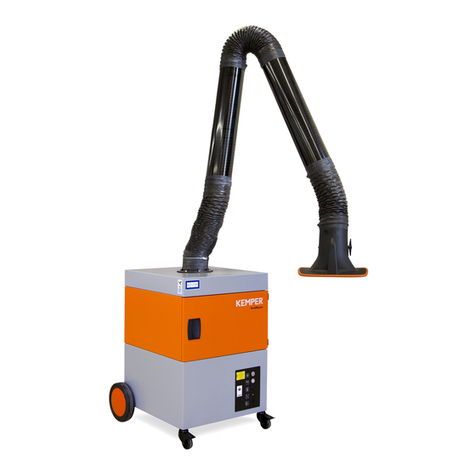
Kemper Dusty User manual

KEMPER
Dusty
Part No. 150 0471


1
1. Application and Mode of Operation ...….… 2
2. Safety Instructions …...…..…..……….. 2 - 3
3. Operation Elements and Function …..….. 3
4. Placing into Operation ................................ 4
5. Emptying of the
Dust Collection Container .......................... 5
6. Cleaning of the Filter Cartridge ….............. 6
7. Replacement of Carbon Brushes …........... 7
8. Fastening of the Filter Unit …................….. 7
9. List of Spare Parts …................................... 8
10. Technical Specification .......................….... 8
11. Drawing ….................................................... 9
12. European Community Declaration
of Conformity …......................................... 10
13. Troubleshooting ….........………................. 11
14. Wirering Diagrams …....…................. 12 - 15

2
1. Application and Mode of Operation
The
KEMPER
Dusty is designed for the extraction of hazardous substances, which are produced
by several electric welding works.
Basically the machine can be used for all operations where particles of hazardous substances,
i.e. fumes and dusts will be discharged. No sparks (e.g. during grinding) may be absorbed into
the filter device.
The released hazardous substances are collected by a funnel nozzle and are led into the filter unit
with the extracted airflow. Here the particles of hazardous substances are intercepted at the surface
of the installed filter cartridges.
The cleaned air will be extracted by the turbines and returned into the working area.
Only tested and approved filter units may be used in this so-called air circulation process,
during the extraction of welding smoke with carcinogenic particles (e.g. stainless steel),
according to the legal regulations. The particles, which are collected at the filter cartridges, are
discharged by automatic compressed-air impetus. They drop into a dust reservoir and
can be taken out for disposal.
2. Safety Instructions
Caution:
When using electrical equipment you have to take notice of basic safety instructions
for the protection against electro shock, injury- and fire danger!
Please read through this manual before operating the unit and make sure that you
have comprehended all information.
Please read through and take notice of the following instructions
before operating the machine!
• Keep the operation and maintenance manual handy.
• Protect the connecting cable against heat, oil and damages by sharp edges.
• The power line regularly has to be examined for indications of damages.
• The filter unit should not be used, if the status of the power line is not acceptable.
• Take care of the correct voltage supply.
• Pull the power plug before opening the filter unit.
• During the cleaning and maintenance of the filter device, replacement of parts or change-over
to another function the filter unit has to be separated from the electricity network.
• Always read the specifications on the type plate.
• The machine always has to be installed safely and the brakes of the guide rollers
tightened at standstill.
• Protect the machine against moistness and humidity.
• Check the filter unit regularly for any damages.
• Always use original spare parts.
• Please use exclusively dry and oil-free compressed air with an operating pressure
of max. 3 bar for the manual cleaning.
(For cleaning see chapter 6, page 6 „Cleaning of filter cartridge“)
• The filter unit should not be moved by the connected acquisition elements (exhaust hose)
and connecting cables.
• Update the funnel nozzle, if possible by utilisation of the thermic qualified
welding smoke movements.
• Don’t use the filter unit, if one or more parts of the filter unit are faulty, not existing or damaged!
In either case contact the
KEMPER
service department under tel. +49 (0) 2564 / 68-0.
• Don’t put any item (e.g. welding rod) into the suction and insufflations slot.

3
• The free air outlet at the blow out grating should not be constrained by any item.
• Don’t use the filter unit with closed suction opening or if the suction hoses are plugged.
• Never operate the machine without filter cartridges. Air contaminations lead to damages
to s.o.’s health or destruction of the turbine!
• Dispose the filter cartridges according to the legal regulations.
• Don’t use the unit to extract oil mist containing welding fumes, as well as during the WIG welding
procedure of stainless steel.
• Don’t use the unit for extracting easy flammable or explosive gases or dusts as e.g. aluminium
dust and wood dust.
• Don’t use the unit for the extraction of burning or glowing substances as e.g. cigarettes, matches,
metallic dusts or rather splinters, sheets of paper, cleaning tissues, etc.
• Don’t use the unit to extract sparks (e.g. of a grinding process).
• Don’t use the unit to extract aggressive substances.
• Don’t use the unit to extract any liquids.
• Don’t use the unit to extract organic substances
• For extraction of carcinogenic welding dusts (e.g. materials containing nickel or chromates)
you have to observe the regulations of TRGS 560 “Recirculation of air during working with
carcinogenic hazardous substances”.
3. Operation Elements and Function
ON/OFF – switch
Monitor light for saturation of filter cartridges
The saturation of the filter cartridges will be checked continuously during the operation of
the unit. The cleaning of the filters is necessary as soon as the monitor light is activated.
(For cleaning see chapter 6, page 6 „Cleaning of filter cartridge“)
Adjusting knob for suction performance
The suction performance can be adjusted to the individual application by using
the adjusting knob.
= higher suction performance
= lower suction performance
2
3
O
I
Filterüberwachung
Filter monitoring
Contrôle de
saturation des filtres
Absaugleistung
extraction capacity
Puissance d’aspiration
5
1
2
34
6
Von-Siemens-Str. 20 · D-48691 Vreden
Tel. +49 (0)2564 /68 -0 · Fax +49 (0)2564 /68 -120
welding, cutting and more...
nächste Wartung
next maintenance
prochaine révision
Dusty
1
1
23

4
4. Placing into Operation
• Insert the stub of the suction hose (optional) to the connection port at the front of the filter unit.
You can insert up to two suction hoses to the unit. Please keep the cover of the second
connection port closed if you do not use it.
• Connect a funnel nozzle (optional) to the other end of the hose and bring the extraction funnel
of the of the nozzle into position that the most effective extraction of the welding smoke is
possible.
• Secure the filter unit by locking the brakes at the guide rollers.
• Please check if all catches at the unit are locked.
• Switch the filter unit off via the On/Off switch.
• Connect the filter unit to the power supply (230 V AC).
• Switch the filter unit on via the On/Off switch. You can adjust the suction performance
to any demand via the adjusting knob.
• The filter unit is ready for operation now.
inlet connector for
non-heating appartus adjusting knob
on/off switch
connection port
catch
guide rollers with brakes
cover

5
5. Emptying of the Dust Collection Container
You have to check the liquid level of the dust collection container regularly. The container has to
be emptied if it is brimmed. The timeperiod between two emptying processes are depending on
the type and the duration of the welding work. We recommend to check the liquid level inside the
container before resp. after using of the filter unit. To avoid any contact with the welding smoke
/dusts you should wear protection gloves and breathing masks during emptying of the container.
• Switch the filter unit off and disconnect it from the power supply.
• Open both catches at the lower side of the unit.
• Remove the upper part of the unit with the filter and the turbine inside the dust collection
container.
Make sure that you do not damage the sealing around the unit.
• Dispose the welding smoke / dust which is inside of the dust collection container according
to legal regulations.
• Remount the cleaned collection container to the unit and connect the power supply to the unit.
The unit is ready for operation now.
Please keep in mind: The welding smoke / dusts have to be stored and removed according to
the regulations of the laws for recycling and wastes. Due to different
compositions of the welding smoke/dusts you may have to ask for the
storage and waste codes at your local recycling company.

6
6. Cleaning of the Filter Cartridge
The particles in the extracted air flow attach to the surface of the filter cartridge.
The extraction capacity lowers by and by and the monitor light for filter saturation will be activated
after falling under a certain extraction capacity. You have to clean the filters in this case.
• Switch the filter unit off and disconnect it from the power supply.
• Open both catches at the upper side of the unit.
• Remove the turbine from the filter unit.
Make sure that you do not damage the sealing around the unit.
• Clean the accessible filter surface of the filter cartridge (clean air side) with a blower at a distance
of approx. 5 cm. The dust layer on the outer side of the filter cartridge will fall down. You have to
make sure that the complete surface of the filter cartridge is cleaned. The air stream should
be blown onto the cartridge from top to bottom.
• Put the turbine back onto the filter unit and fasten it to the unit by closing the catches.
• Connect the power supply to the unit. The unit is ready for operation.
You have to repeat cleaning of the filters if the monitor light for filter saturation is still activated.
• The saturated filter cartridge must not be cleaned by compressed air when the dust collection
container has been removed or opened. The devided particles can get back into the air and
pollute it.
Please keep in mind: You need clean, dry and oilfree compressed air of max. 3 bar to clean the
filter cartridge. The distance between filter material and blower pipe should
not be less than 5 cm. Otherwise the filter material can be damaged.
We recommend to wear protection gloves and breathing masks during
cleaning of the filter cartridge.
Inner surface of filter
cartridge (clean air side)
surrounding sealing
filter unit
turbine units
catch
catch

7
7. Replacement of Carbon Brushes
The carbon brushes of a suction turbine in a motor with collector cel can wear.
The lifetime of the carbon brushes is approx. 600 working hours.
We recommend to replace the carbon brushes regularly to ensure a proper operation of the unit.
To replace the carbon brushes:
• Disconnect the power supply.
• Loosen the fastening screw from the cover and remove the cover.
• Remove the black plastic covers from the turbines.
• Unscrew the carbon brushes and loosen the cables.
• Insert new carbon brushes.
• Remount the unit by following the steps in reverse order.
8. Fastening of the Filter Unit
For any transportation the filter unit can be fastened with a belt, to secure against removing.
The brakes of the castors have to be locked for transportation.
max. pulling force of belt: 200 N

8
9. List of Spare Parts
10. Technical Specification
230 V/AC 115 V/AC
Capacity: 340 m3/h 340 m3/h
Pressure: 18.100 Pa 18.100 Pa
Power supply: 230 V / AC 115 V / AC
Amperage: 8,7 A 14,4 A
Motor performance: 1,6 kW 1,6 kW
Phases (Amperage): 1 ~ 1 ~
Frequency: 50 Hz 50 Hz
Weight: 21 kg 21 kg
Description
PTFE filter cartridge
Set of carbon brushes
On/Off switch
Monitor switch for filter saturation, red / 230 V
Monitor switch for filter saturation, red / 115 V
Speed frequency control / 230 V
Speed frequency control / 115 V
Micro-fuse 10 A, time-lag
Micro-fuse 20 A, time-lag
Pressure differential switch
Suction turbine 230 V/ AC
Suction turbine 115 V/ AC
Guide roller
Guide roller, lockable
Power cable, 230 V
Item
1
2
3
4
5
6
7
8
9
10
11
12
13
14
15
Part No.
109 0244
360 1194
360 0580
360 1850
360 0018
63 100 000 01
63 100 000 02
360 1984
360 1998
360 1370
19 502 102
19 515
146 0167
146 0168
124 0426

9

10
European Community Declaration of Conformity
according to European Community machine standard 89/392/EWG, appendix II A
The manufacturer:
KEMPER GmbH
Von-Siemens-Str. 20
D-48691 Vreden
confirms that the construction of the following machine (or system or part of machine, etc)
Description, Name
KEMPER Dusty
with manual filter cleaning (Extraction unit, welding)
Part-No. 63 100
for connection of two ports NW 45
is confirm with the regulations of the machine standard 98/37/EG, also confirm all modifications
and confirm with the following regulations of the European Community:
89/392/EWG, 91/368/EWG and 96/44/EWG European Community machine standard
89/336/EWG and 92/31/EWG EMV standard version
87/404/EWG and 90/488/EWG Regulation for compressed air reservoirs
73/23/EWG Regulation for low voltage
93/68/EWG Regulation for labelling
Applicable harmonized standards, especially
EN 292 part 1 and part 2 Security of machinery
EN 50081 part 1 Law referring to the electromagnetic
Transmission of devices
EN 61000-6 part 2 Law to the electromagnetic
consistency of devices
Applicable national and technical specifications, especially
VDE 0100 Construction of power plants with a nominal voltage of up to 1000V
VDE 0113 Electrical equipment of industrial machines
UVV VBG 1 General regulations
Confirmed in: D - VREDEN
Confirmed on: 04. Mai 2005
Signee: Dipl.-Ing. Manfred Könning
(Chief Technical Engineer)

11
Malfunction
Filter unit can not
be switched on.
Speed frequency can
not be adjusted.
Extraction capacity
is too low.
Welding smoke is
escaping through
the outlet opening.
Possible causation
- No power supply.
- Power socket not connected
correctly.
- Motor protection faulty.
- Adjusting knob has
been loosened from the
potentiometer.
- Suction hose / capturing
device is clogged.
- Filter cartridge is saturated.
- Unappropriate sealing
between filter cartridge
and filter housing.
- Holes in the filter cartridge.
Troubleshooting
- Connect the filter unit to the
power supply.
- Check if the power cable has
been plugged into the socket
properly.
- Replace power cable.
- Replace fuse in the fuse carrier
at the inlet connector for
non-heating apparatus.
- Remove the cover plate from the
adjusting knob and refasten the
fixing bout of the adjusting knob.
- Clean the suction hose /
capturing device.
- Clean the filter cartridge
(see chapter 6, page 6).
- Refasten the mounting screws
of the filter cartridge.
- Replace the filter cartridge.
- Contact
KEMPER
service
department.
13. Troubleshooting

12

13

14

15


Table of contents
Other Kemper Scrubber manuals