kenall SimpleSeal CMEXR Series User manual

www.Kenall.com P: 800-4-Kenall F: 262-891-9701 10200 55th Street Kenosha, WI 53144
When you see this image, you will know the Kenall product shown or described is designed and manufactured in the USA with components purchased from US suppliers, and meets the Buy
American requirements under the ARRA. Kenall has not determined the origin of its domestically purchased components or the subcomponents thereof. May be covered by patents found at
www.kenall.com/patents. Content of speciation sheets is subject to change; please consult www.kenall.com for current product details. © 2015 Kenall Mfg. Co. All rights reserved.
CMEXR_MMEX_METDU_METSR_METSU_METSW_F-3833_113016
Ceiling/Wall Surface & Recess Mount Exit Signs OPERATING INSTRUCTIONS 1
CMEXR, MMEX, METDU, METSR, METSU, and METSW Series
IMPORTANT SAFEGUARDS
When using electrical equipment, basic safety precautions should always be followed, including the following:
READ AND FOLLOW ALL SAFETY INSTRUCTIONS
THIS PRODUCT MUST BE INSTALLED IN ACCORDANCE WITH THE APPLICABLE INSTALLATION CODE BY A PERSON
FAMILIAR WITH THE CONSTRUCTION AND OPERATION OF THE PRODUCT AND THE HAZARDS INVOLVED. FOLLOW
ANY SPECIFIC INSTRUCTION ON LUMINAIRE LABELS.
●Do not mount near gas or electric heaters.
●Equipment should be mounted in locations and at heights where it will not be readily subject to tampering by unauthorized personnel.
●The use of accessory equipment not recommended by the manufacturer may cause an unsafe condition.
●Do not use this equipment for other than intended use.
●Servicing of this equipment should be performed by qualified personnel.
●WARNING: Disconnect power to the circuit before wiring fixture.
●Read all fixture markings and labels to insure correct installation of the fixture. Additional information may be located on the fixture or
in supplemental instructions sheets, separate from this instruction sheet, regarding orientation, mounting restrictions and optional
equipment.
SAVE THESE INSTRUCTIONS
OPERATING INSTRUCTIONS
APPLICATIONS
Mighty Mac MMEX series, Millenium Metrex METDU, METSR, METSU, METSW series, SimpleSeal CMEXR series exit signs
with EL or CEL Emergency Battery Pack options. See fixture labels for instructions. METSW unit shown, other units similar.
FEATURES
-Sealed, maintenance-free nickel-cadmium battery. EL option is suitable for use in 10 C (50 F) to 45 C (113 F) environments.
CEL option includes a thermostatically controlled battery warmer and is suitable for use in -45 C (-49 F) to 45 C (113 F)
environments. Self-testing circuitry automatically conditions the battery and performs regularly scheduled tests that conform
to NFPA 101 Life
-Safety Code. Self-diagnostic circuitry monitors battery, charger, power transfer and lamp functions.
INSTALLATION
-Follow Kenall Installation Instruction Sheet for proper mounting,
assembly and wiring of unit.
-Fixture is shipped with battery disconnected.
-After installing electrical chassis and making field wiring connections (AC
power OFF), connect polarized 2-pin battery connector to PC board
assembly.
-Exit legend will illuminate for a few seconds and then extinguish. This
signals that the battery is properly connected and is protected from
discharging until AC power is established.
-Carefully align front stencil assembly over status/test pushbutton and
indicator. Snap front stencil assembly to housing.
START-UP
-Do not apply power to fixture unless supply can be maintained for at least 7 days without interruption.
-If battery is not connected when power is applied, the self-diagnostic feature will detect the missing battery and the status
LED will display a steady red signal. Connect the battery and reset the system by pressing and holding the manual push test
switch for approximately 7 seconds.
-Upon initial power-up, the fixture will supply a trickle charge to the battery for 90 minutes. Then it will switch to full charge
mode for approximately 24 hours. The fixture will then condition the battery with a pair of 90 minute discharge and 24 hour
recharge cycles.
LOAD LEARNING
-During the final discharge/recharge cycle of the battery conditioning function, the self-diagnostic feature will measure the
operating current of the internal and external (if equipped) exit sign(s).
-Any time the total (internal or external) exit sign load is intentionally altered, the system must be reset by pressing and
holding the manual test pushbutton for approximately 7 seconds. Failure to do so will result in a lamp fault indication.
NORMAL OPERATION
Normal operation is indicated by a steady green signal from the status LED. This indicates the fully charged battery is receiving
a maintenance (trickle) charge and normal AC power is present. The normally on exit sign(s) will operate from normal AC power

www.Kenall.com P: 800-4-Kenall F: 262-891-9701 10200 55th Street Kenosha, WI 53144
When you see this image, you will know the Kenall product shown or described is designed and manufactured in the USA with components purchased from US suppliers, and meets the Buy
American requirements under the ARRA. Kenall has not determined the origin of its domestically purchased components or the subcomponents thereof. May be covered by patents found at
www.kenall.com/patents. Content of speciation sheets is subject to change; please consult www.kenall.com for current product details. © 2015 Kenall Mfg. Co. All rights reserved.
CMEXR_MMEX_METDU_METSR_METSU_METSW_F-3833_113016
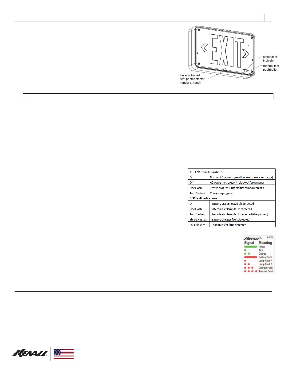
OPERATING INSTRUCTIONS 2
User Initiated Tests
-A single momentary actuation of the laser-activated photodetector or the
manual test pushbutton will initiate a one-minute test. The normally off
emergency lamps will come on and the status LED will display single green
flashes, signaling a test is in progress.
-Within the first 5 seconds, pressing the manual test pushbutton twice will
change the test duration to 30 minutes, three times for 60 minutes, or four
times for 90 minutes.
-Actuating the photodetector or the manual test pushbutton after the first 5
seconds will cancel any user initiated test.
Automatic Tests
-Automatic tests meet or exceed requirements of NFPA 101 Life Safety
Code, Section 4.6, Article 7.9.3:
Monthly Test 30 minute cycle every 30 days.
-These tests allow the self-diagnostic circuit to monitor battery discharge and power transfer functions and exercise the
battery to optimize its capacity. The status LED will display single green flashes, signaling a test is in progress. Automatic
tests can be delayed 12 hours by actuating the laser-activated photodetector or the manual test pushbutton once during an
automatic test.
EMERGENCY OPERATION
-When the AC voltage drops below a predetermined level either due to a power failure or a brownout condition, the unit will
switch to emergency operation. The status LED will turn off, signaling normal AC power is not present. Unit will remain in
emergency operation for 10 minutes after resumption of normal AC power to allow normal power supply to stabilize.
-Upon resumption of normal operation there will be a 90 minute time delay before a full charge is applied to the battery to
allow the unit to reach normal operating temperature (CEL option). During full charge the status LED will display two green
flashes. The charger will return a depleted battery to full capacity within 24 hours. When the battery has reached full capacity,
maintenance (trickle) charging begins and the status LED will display steady green.
-In the event of a prolonged power outage, the battery is protected from deep
discharge by a low voltage disconnect circuit.
SELF DIAGNOSTICS
Status Indicator
A single dual-color status/fault LED is provided to allow monitoring of the circuit
function.
Battery
The battery condition is constantly monitored during normal operation, tests and
charge cycles. A malfunctioning or end-of-life battery will terminate any charge or
test and return the unit to normal operation. The status indicator will display steady
red.
LED Exit Lamps
The LED lamp condition is constantly monitored during normal operation and test
cycles. A variation of more than 50% of nominal load current will cause the status indicator to display single red
flashes.
Remote LED Exit Lamps (if equipped)
The LED lamp condition is constantly monitored during normal operation and test cycles. A variation of more
than 50% of nominal load current will cause the status indicator to display two red flashes.
Charger
The charger function is constantly monitored during battery charging. A charger malfunction will terminate the
charge and return the unit to normal operation. The status indicator will display three red flashes.
Transfer
The normal-to-emergency and emergency-to-normal power transfer functions are monitored at the beginning and end of each
test cycle. A transfer circuit malfunction will cause the status indicator to display four red flashes.
CUSTOMER SERVICE
For technical assistance, call 1-800-4KENALL (1-800-453-6255).
WARRANTY
This product is warranted by Kenall to be free of defects in workmanship and materials for a period of one (1) year from the date of the invoice. LED
lamps and internal power regulation components are warranted for a period of five (5) years from the date of the invoice against defects in materials and
workmanship. The external DC power supply carries a three year warranty from the date of the invoice.
The warranty is void if all power and dimming signal wiring is not completely shielded against grounded aluminum conduit and installed with a suitable
MRI room filter (by others).
Kenall reserves the right to issue credit, repair, or replace the defective merchandise, at its discretion, upon notification and confirmation by its local
representative of the defect. Kenall also reserves the right to test and examine the defective product if the defect is questionable and to deny the
warranty herein for any product altered, improperly installed, installed in applications for which it is not intended. This includes operation in ambient
temperatures above stated limits for any length of time. Failure by electrical surge shall not be covered under warranty.
Kenall assumes no responsibility for labor or freight costs incurred in connection with the installation, removal, or replacement of products determined to
be defective or any other consequential or incidental damages arising from the use of the product. Kenall’s entire liability on any claim of loss or damage

www.Kenall.com P: 800-4-Kenall F: 262-891-9701 10200 55th Street Kenosha, WI 53144
When you see this image, you will know the Kenall product shown or described is designed and manufactured in the USA with components purchased from US suppliers, and meets the Buy
American requirements under the ARRA. Kenall has not determined the origin of its domestically purchased components or the subcomponents thereof. May be covered by patents found at
www.kenall.com/patents. Content of speciation sheets is subject to change; please consult www.kenall.com for current product details. © 2015 Kenall Mfg. Co. All rights reserved.
CMEXR_MMEX_METDU_METSR_METSU_METSW_F-3833_113016
resulting from a defective product is limited to the replacement price of the product.
The foregoing warranty is exclusive of all other warranties and no other warranties of any kind are expressed or implied.
This manual suits for next models
5
Table of contents
Other kenall Lighting Equipment manuals

kenall
kenall Sentinall S511 Series User manual

kenall
kenall CSMRI Series User manual

kenall
kenall MEDMASTER MAC2B Series User manual

kenall
kenall Medmaster Softstep MSL Series User manual

kenall
kenall RESIDENCE MPWV Series User manual

kenall
kenall MILLENIUM METREX METSW Series User manual

kenall
kenall LUXTRAN LTSIU Series User manual
Popular Lighting Equipment manuals by other brands

Signtex
Signtex MoonLite LED MAE-AC Series Installation instructions and owner's manual

Satco
Satco NUVO 67-132 Installation and safety instructions

Perel
Perel EWL512T user manual

Armacost Lighting
Armacost Lighting RibbonFIex Pro quick start guide

Hella
Hella KL 7000 Mounting instructions

Eterna
Eterna RDL12 installation instructions