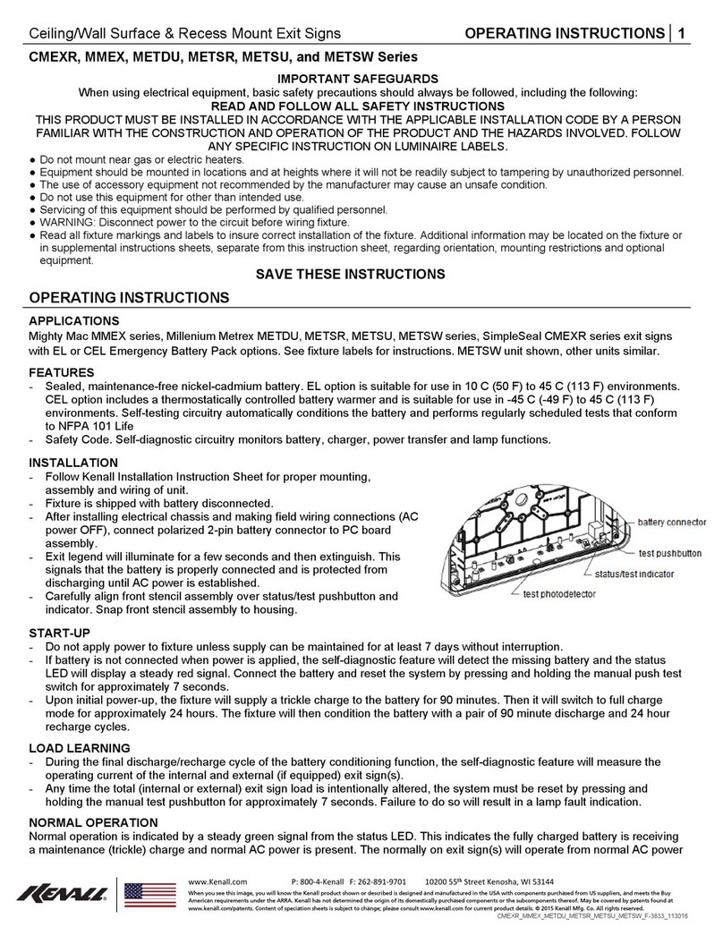
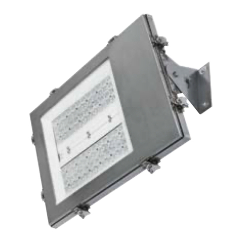
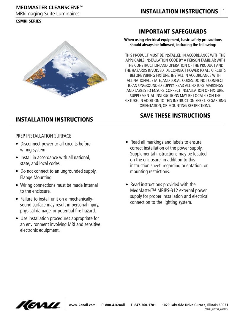
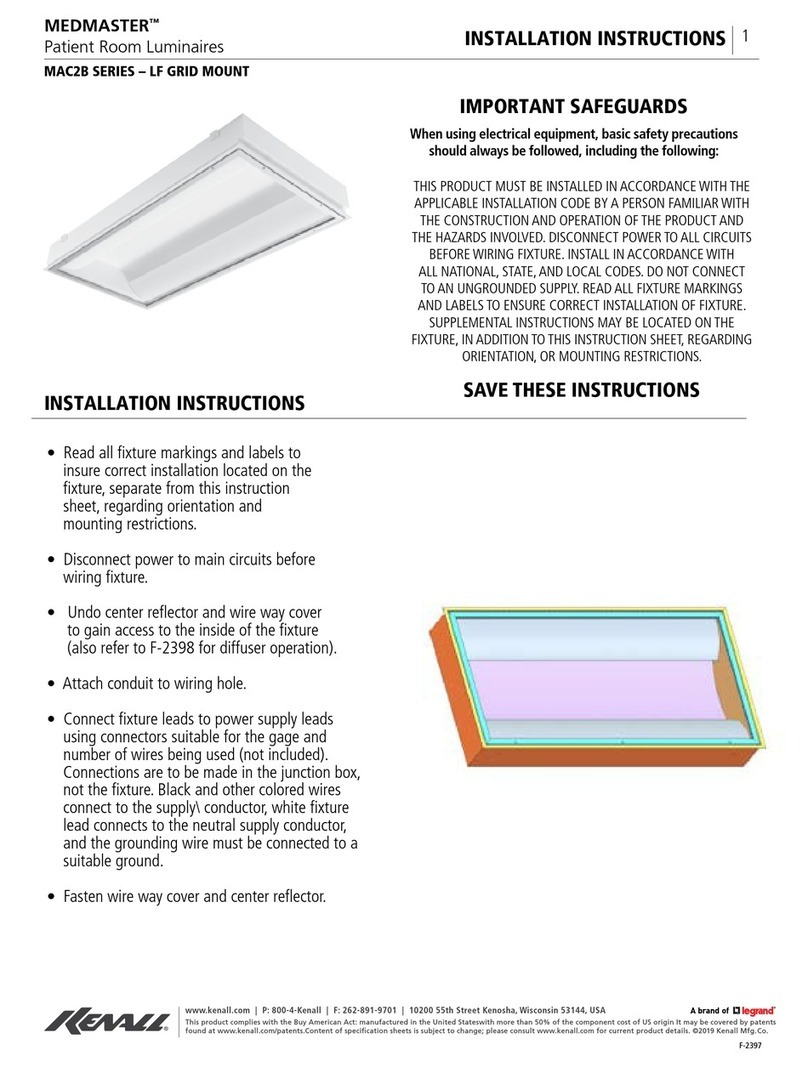
kenall Sentinall S511 Series User manual

www. kenall.com P: 800-4-Kenall F: 847-360-1781 1020 Lakeside Drive Gurnee, Illinois 60031
1
INSTALLATION INSTRUCTIONS
S511-092613
IMPORTANT SAFEGUARDS
When using electrical equipment, basic safety precautions
should always be followed, including the following:
THIS PRODUCT MUST BE INSTALLED IN ACCORDANCE WITH THE
APPLICABLE INSTALLATION CODE BY A PERSON FAMILIAR WITH
THE CONSTRUCTION AND OPERATION OF THE PRODUCT AND
THE HAZARDS INVOLVED. DISCONNECT POWER TO ALL CIRCUITS
BEFORE WIRING FIXTURE. INSTALL IN ACCORDANCE WITH
ALL NATIONAL, STATE, AND LOCAL CODES. DO NOT CONNECT
TO AN UNGROUNDED SUPPLY. READ ALL FIXTURE MARKINGS
AND LABELS TO ENSURE CORRECT INSTALLATION OF FIXTURE.
SUPPLEMENTAL INSTRUCTIONS MAY BE LOCATED ON THE
FIXTURE, IN ADDITION TO THIS INSTRUCTION SHEET, REGARDING
ORIENTATION, OR MOUNTING RESTRICTIONS.
SAVE THESE INSTRUCTIONS
INSTALLATION INSTRUCTIONS
Luminaires for High Abuse Applications
SENTINALL™
S511 SERIES
1. Read all xture markings and labels to insure correct installation of the xture. Additional information may be
located on the xture, separate from this instruction sheet, regarding orientation and mounting restrictions.
2. For Peace of Mind Guarantee®, xture must be mounted to building with at least 4 fasteners
(4 point mounting). Attachment to the electrical box only will not insure proper xture performance.
3. Disconnect power to the circuit before wiring xture.
4. Remove lens/housing. Remove reector by popping it out..
5. Place xture over an installed electrical junction box. Locate and drill 4 pilot holes in mounting surface. Use
xture base as template. Using 1/4-20 fasteners and anchors appropriate for the mounting surface, (not
supplied), mount xture base to building. Orient base of S511L so that socket is up when lamp is installed.
6. Connect xture leads to power supply leads using connectors suitable for the gauge and number of wires being
used (not included). Connections are to be made in the junction box, not the xture. Black xture lead connects
to the supply conductor, white xture lead connects to the neutral supply conductor, and the grounding wire
must be connected to a suitable ground.
7. As applicable, reassemble ballast housing, reectors, wireway covers, etc. to the base. Install lamp. Mount
diffuser/refractor to base using Torx®fasteners (included) and 9500 screwdriver (ordered separately).
NOTE: Check gasket for proper seal between lens/housing and mounting surface. To ensure the xtures watertight
integrity, especially if the xture is mounted in direct exposure to the elements, caulk between the mounting surface
and base using a high quality caulking material.

www. kenall.com P: 800-4-Kenall F: 847-360-1781 1020 Lakeside Drive Gurnee, Illinois 60031
2
INSTALLATION INSTRUCTIONS
S511-092613
Uneven Surface Mounting Plate
1. Read all xture markings and labels to insure correct installation of the xture. Additional information may be
located on the xture, separate from this instruction sheet, regarding orientation and mounting restrictions.
If the xture is to be mounted on uneven surfaces, in wet or damp locations, such as concrete block or brick
masonry, the mounting plate must be used and installed per these instructions. 1/4 diameter fasteners and
appropriate anchors must be used.
2. Disconnect power to the circuit before beginning work.
3. Use Mounting Plate as a template and mark the 4 mounting holes. Drill pilot holes in the mounting surface
appropriate for the anchor being used, and install anchors. To insure the xture’s watertight integrity, especially
if the xture is mounted in direct exposure to the elements, caulk between the mounting surface and Plate
using a high quality caulking material. Apply a full, continuous bead of caulk in an upside down “U” shape to
the back of the mounting plate to the outside of all mounting holes.
4. Disassemble Sentinall™by removing diffuser and reector. Using fasteners appropriate for the anchors, (not
supplied), align xture base over Mounting Plate, insert fasteners through xture base and Mounting Plate into
anchors in building. Gasket on back of xture base should form a tight seal to the Mounting Plate.
5. Connect xture leads to power supply leads using connectors suitable for the gauge and number of wires being
used (not included). Black xture lead connects to the supply conductor, white xture lead connects to the
neutral supply conductor, and the grounding wire must be connected to a suitable ground.
6. Install lamp, reector and diffuser to base using Torx®fasteners (included) and 9500 screwdriver (ordered
separately). On very uneven surfaces, additional caulking may be necessary to ll gaps between building and
Mounting Plate. Run caulk bead around perimeter of Mounting Plate.
Uneven Surface Mounting - Damp or Wet Locations
1. Read all xture markings and labels to insure correct installation of the xture. Additional information may be
located on the xture, separate from this instruction sheet, regarding orientation and mounting restrictions.
When mounting adapter to wall, casting must be oriented with long dimension vertical so that xture can be
installed with lamp base up.
2. Disconnect power to the circuit before wiring xture.
3. Locate and drill 2 pilot holes in mounting surface. Use surface adapter as template. Using 1/4-20 fasteners and
anchors appropriate for the mounting surface, (not supplied), mount surface adapter to building. Attach surface
conduit to back entry, or if side entry is used, remove side plug, and install in back conduit opening. All unused
openings must be plugged.
4. Connect xture leads to power supply leads using connectors suitable for the gauge and number of wires being
used (not included). Connections are to be made in the surface adapter. Black xture lead connects to the
supply conductor, white xture lead connects to the neutral supply conductor, and the grounding wire must be
connected to a suitable ground.
5. Mount wired baseplate to casting using the single No. 10-24 x 5/8 screws provided. Install lamp. Mount
diffuser/refractor to base using Torx®fastener (included) and 9500 screwdriver (ordered separately).
NOTE: To ensure the xtures watertight integrity, especially if the xture is mounted in direct exposure to the
elements, caulk between the mounting surface and base using a high quality caulking material.
ACCESSORIES: Photocontrolls-To prevent cycling, xture must be installed so that indirect xture light or other
ambient light is not visible to photocell. If xture cycles it is not a xture defect. In some cases additional hood (C-
1076) may help. Contact Factory.
www. kenall.com P: 800-4-Kenall F: 847-360-1781 1020 Lakeside Drive Gurnee, Illinois 60031
3
INSTALLATION INSTRUCTIONS
S511-092613
Kenall high abuse luminaires are designed and built to take exceptional physical punishment. When installed
according to our instructions, Kenall will repair or replace any xture rendered inoperable due to physical abuse
for the product life of the original installation.
All standard xtures manufactured by Kenall are warranted to be free of defects in workmanship and materials
for a period of one year from the date of invoice. Additionally, Kenall will replace broken diffusers, refractors, exit
housings, or xtures rendered inoperable by physical abuse, any time during their product life free. A toll-free
hot-line number, 1-800-331-1416 is provided for immediate resolution of any eld problems encountered in
connection with the use of Kenall’s exclusive high abuse lighting products.
Kenall reserves the right to issue credit, repair, or replace the defective merchandise, at its discretion, upon
notication and conrmation by its local representative of the defect. Kenall also reserves the right to test
and examine the defective product if the defect is questionable and to deny the warranty herein for any product
altered, improperly installed, installed in applications for which it is not intended. This includes operation in
ambient temperatures above stated limits for any length of time. Failure by electrical surge shall not be covered
under warranty.
Kenall assumes no responsibility for labor or freight costs incurred in connection with the installation, removal,
or replacement of products determined to be defective or any other consequential or incidental damages arising
from the use of the product. Kenall’s entire liability on any claim of loss or damage resulting from a defective
product is limited to the replacement price of the product.
The foregoing warranty is exclusive of all other warranties and no other warranties of any kind are expressed
or implied.
WARRANTY
CUSTOMER SERVICE
For technical assistance, call 1-800-4KENALL (1-800-453-6255).
Table of contents
Other kenall Lighting Equipment manuals

kenall
kenall LUXTRAN LTSIU Series User manual

kenall
kenall RESIDENCE MPWV Series User manual

kenall
kenall SimpleSeal CMEXR Series User manual

kenall
kenall MEDMASTER MAC2B Series User manual

kenall
kenall Medmaster Softstep MSL Series User manual

kenall
kenall CSMRI Series User manual

kenall
kenall MILLENIUM METREX METSW Series User manual
Popular Lighting Equipment manuals by other brands

Energyficient
Energyficient Q-Lume instruction manual

ITC
ITC Compel 690UVX Install instructions

Lucci fini
Lucci fini 2100249 installation instructions

Vision & Control
Vision & Control LDLF30x300-B470/24V/-a Instructions for use

Spectroline
Spectroline NANO 365 Series manual

Dr. Mach
Dr. Mach Quintaflex R96 Directions for use