manuals.online logo
Brands
  1. Home
  2. •
  3. Brands
  4. •
  5. Kenwood
  6. •
  7. Receiver
  8. •
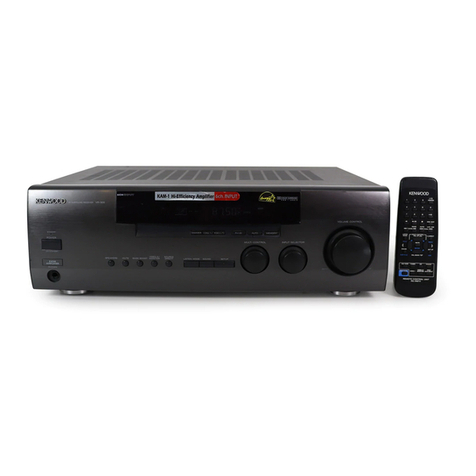
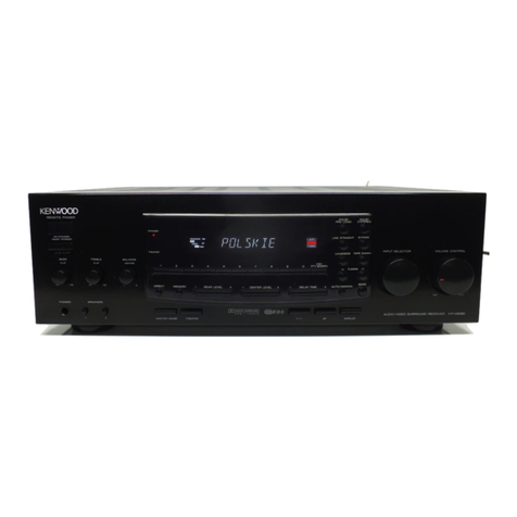
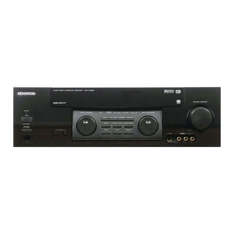
  9. Kenwood KR-V7070 User manual

Kenwood KR-V7070 User manual

AUDIO/VIDEO
RECEIVER
KR-V
70/70
INSTRUCTION
MANUAL
KENWOOD
CORPORATION
For
your
records
Record
the
serial
number,
found
on
the
back
of
the
unit,
in
the
spaces
designated
on
the
warranty
card,
and
in
the
space
provided
below.
Refer
to
the
madel
and
serial
numbers
whenever
you
call
upon
your
dealer
for
information
or
service
on
this
product.
Model___
SSS
Serial
Number
Unpacking
Unpack
the
unit
carefully
and
make
sure
that
all
accessories
are
put
aside
so
they
will
not
be
lost.
Examine
the
unit
for
any
possibility
of
shipping
damage.
If
your
unit
is
darnaged
or
fails
to
operate,
notify
your
dealer
immediately.
!f
your
unit
was
shipped
to
you
directly,
notify
the
shipping
com-
pany
without
delay.
Only
the
consignee
(the
person
ar
company
receiving
the
unit}
can
file
a
claim
against
the
carrier
for
shipping
damage.
We
recommend
that
you
retain
the
original
carton
and
packing
materials
for
use
should
you
trans-
port
or
ship
the
unit
in
the
future.
;
22
Accessories
FM
indoor
antenna
(1)
AM
loop
antenna
{T)
Loop
antenna
stand
(1)
Antenna
adaptor
(1)
Remote
contro!
unit
(1)
Batteries
(R6/AA}(2}
AC
plug
adaptor
{7)*
*
Use
to
adapt
the
plug
on
the
powar
cord
to
the
shape
of
the
wall
outlet.
[Accessory
only
for
regions
where
use
is
necessary.)
THT.
Units
are
designed
for
operation
as
follows.
U.S.A.
att
Canada.
.ccscccscrscsenersrrrerenenerceriererirrtsrenrirtereeeniaseres
A€
120
V
anly
Australia...
eiidiete
ccrnesureeverersecernesasrvecterrrecersevarss
AG
240
V
only
Other
countries
penn?
116~
128
/
220~240
V
switchable
fo
ensure
Sate
ope
“KR
“V¥7070
(En
AC
voltage
selection
This
unit
operates
on
110
-
120
volts
or
220
-
240
volts
AC.
The
AC
voltage
selector
switch
on
the
rear
panel
is
set
to
the
voltage
that
pre-
vails
in
the
area
to
which
the
unit
is
shipped.
Before
connecting
the
power
cord
to
your
AC
outlet,
make
sure
that
the
setting
position
of
this
switch
matches
your
line
voltage.
If
not,
it
must
be
set
to
your
voltage
in
accordance
with
the
fallowing
direction.
AC
voltage
Selector
switch
Note:
Move
switch
lever
to
match
your
line
voltage
with
Our
warranty
does
not
cover
damage
caused
by
excessive
line
a
small
screwdriver
or
other
pointed
tool.
voltage
due
to
improper
setting
of
the
AC
voltage
selector
switch.
WARNING:
TO
PREVENT
FIRE
OR
ELECTRIC
SHOCK,
DO
NOT
EXPOSE
THIS
APPLIANCE
TO
RAIN
OR
MOISTURE.
CAUTION
CAUTION:
TO
REDUCE
THE
RISK
OF
ELECTRIC
SHOCK,
DO
NOT
REMOVE
COVER
RISK
OF
ELECTRIC
SHOCK
(OR
BACK).
NO
USER-SERVICEABLE
PARTS
INSIDE,
REFER
SERVICING
TO
QUALIFIED
DE
NPL
OEED
SERVICE
PERSONNEL.
ie
THE
LIGHTNING
FLASH
WITH
ARROWHEAD
SYMBOL,
WITHIN
AN
EQUILATERAL
TRIANGLE,
IS
INTENDED
TO
ALERT
THE
USER.
TO
THE
PRESENCE
OF
UNINSULATED
“DANGEROUS
VOLTAGE”
WITHIN
THE
PRODUCT’S
ENCLOSURE
THAT
MAY
BE
OF
SUFFICIENT
MAGNITUDE
TO
CONSTITUTE
A
RISK
OF
ELECTRIC
SHOCK
TO
PERSONS,
THE
EXCLAMATION
POINT
WITHIN
AN
EQUILATERAL
TRIANGLE
IS
INTENDED
TO
ALERT
THE
USER
TO
THE
PRESENCE
OF
IMPORTANT
OPERATING
AND
MAINTENANCE
(SERVICING)
INSTRUCTIONS
IN
THE
LITERATURE
ACCOMPANYING
THE
APPLIANCE.
=
For
the
U.S.A.
FCC
WARNING
This
equipment
may
generate.
or
use
radio
frequency
energy.
Changes
or
modifications
to
this
equipment
may
cause
harmful
interference
unless
the
modifications
are
expressly
approved
in
the
instruction
manual.
The
user
could
lose
the
authority
to
operate
this
equipment
if
an
unauthorized
change
or
modification
is
made.
NOTE:
This
equipment
has
been
tested
and
found
to
comply
with
the
limits
for
a
Class
B
digital
device,
pursuant
to
Part.
18
of
the
FCC
Rules.
These
limits
are
designed
to
provide
reasonable
protection
against
harmful
interference
in
a
residential
installation.
This
equipment
may
cause
harmful.
interference
to
radio
communications,
if
it
is
not
installed
and
used
in
accordance
with
the
instructions,
However,
there
is
no
guarantee
that
_
interference
will
not
occur
in
a
particular
installation.
If
this
equipment
does
cause
harmful
interference
to
radio
or
television
reception,
which
can
be
determined
by
turning
the
equipment
off
and
on,
the
user
is
encouraged
to
try
to
correct
the
interference
by
one
or
more
of
the
following
measures:
_
-—
Reorient
or
relocate
the
receiving
antenna.
—
—
Increase
the
separation
between
the
equipment
and
receiver.
-
—-
Connect
the
equipment
into
an
outlet
on
a
circuit
different
from
that
to
which
the
receiver
is
connected,
—~—
Consult
the
dealer
or
an
experienced
radio
/
TV
technician
for
help.
For
the
U.S.A.
Note
to
CATV
system
installer:
This
reminder
is
provided
to
call
the
CATV
system
installer’s
attention
to
Article
820-40
of
the
NEC
that
provides
guidelines
for
proper
grounding
and,
in
particular,
specifies
that
the
cable
ground
shall
be
connected
to
the
grounding
system
of
the
building,
as
close
to
the
paint
of
cable
entry
as
practical.
oe
|
__
Special
featur
Re
at
RR
er
A
ae
rmietein
Sieve
teint
Seem
re
re
ie
eros
—
oe
a
ee
ener
=
KR-V7070
(En)
DOLBY
PRO
LOGIC
&
DOLBY3STEREO.
Situs
The
surround
system
reproduces
video
software
program
carrying
the
DX)
(Dov
sunncuno|
mark
with
similar
acoustic
effects
to
movie
theaters.
The
DOLBY
PRO
LOGIC
mode
controls
the
audie
signals
of
the
Front
Left/Right.
Center
and
Rear
surround
channels
using
the
built-in
directivity
enhancer
circuit
to
reproduce
the
feeling
of
sound
motions
realistically.
The
DOLBY
3
STEREO
mode
can
reproduce
the
motions
of
sound
even
when
only
the
front
and
center
speakers
are
used,
by
providing
proper
acoustic
position
using
the
directivity
enhancer
circuit
This
mode
adds
presence
sound
components
obtained
fram
the
DSP
(Digital
Signal
Processor)
to
the
signals
output
from
the
DOLBY
PRO
LOGIC
(Left,
Center,
Right
and
Surround
channets},
allowing
movie
software
programs
to
be
played
with
a
similar
feeling
of
presence
to
movie
theaters
in
a
listening
room
in
home.
DSP
presence
This
mode
adds
presence
sound
components
obtained
from
the
DSP
(Digital
Signal
Processor}
to
the
original
source
signals,
allowing
music
source
entertainment
with
the
feeling
of
pres-
ence
in
an
arena,
stadium
or
jazz
club
in
a
listening
room
at
home.
Contents
=
it
Before
applying
power
Ay
Before
QpplyiING
DOWN
sisi
csc
encadcdehes
sk
deci
sedate
Hanneuvindeveassviandisersiveicoerestectucs
eens
2
NSS
artes’
Bree
WE
OS:
a
eck
eusesc
accents
Seah
dtc
ieen
ucassem
econ
ido
ecaadeael
angete
so
ubeiecaaroatiedeeraeaae
aac
Special
features
Sheds
didi
hk
Satan
irs
athe
at
uene
tea
a
Dy
loan
che
an
ae
eet
betee
ea
spre
Moa
nda
hesnga
geben
ab
agua
dean?
O
System
connection
seeder
beaten
a
vs
reeneecndcnatyy
4
FM
DE-
EMPHASIS/CHANNEL
SPACE
switch...
ahGnatesaives
S
desiaarnadana
a
aiemel
arte
aed
7
Controls
and
indicators
sida
branes
dlaees
us
tenet
des
oes
Oa
teceelaag
is
este
tnd
ce
cin
OS
dott
dear
erway
aoa
baits
iad
casa
Operation
of
remote
control
unit.
icccccccseeeetecceustaceesnseeauniuesaececannaneesicarneensnssssigeereeessrenavearessernnnnrnrnenronerentenerariara
10
Playing
music
batecdarse
ccatesduat
Suites
dace
irabedk
selon
cued
ubd
ines
hitatie
oon
ier
dganbedc
nieluasiansnuleaveeties
detecuanaimananabuctetene.
14
Sound
adjustment
functions
wdssede
Lovie
daha
tit
sete
Rese
Dae
a
i
vatoc
wacarter
eau
de
taattetatoncae
eRe
Denise
eae
12
Recording
hE
Recording
..
babies
Dinwtatalue
dena
ateatistana
tomer
taret
va
dade
naan
ntuoasemustosednee
SF
Copying
tape
(Tape
cubbing)
.
J
seiaherdsiclithas
tataasd
acer
onatentordl
oui
iaan
aati
ee
Broadcast
reception
—
oom
erm
RaceWing
broadest
station
.
Giyiat
site
hein
eine
ed
ID
Receiving
radio
station
by
specifying
its
frequency
«
delet
ach
abnetiecchesunrtwianivecise
AO
Storing
radio
stations
in
memory
(Station
Bee
servvedatverebedevicnbedrevecteiegwuseloesdeah
12
Operation
of
video
components
>
-
es
Playback
ar
videbiape
vale
oces(eearus
ui
aakseisnee
ietaaaue
tacit
ean
baaistuanetaddboncte
tide
Mocieddodeceatatatiaes
18
Recording
Of
VIGGO
SOURCE
5
its
sicsiccccsessdvcivsanterenioknre
mivaisenteadnddeens
sieciedivecesevosvees
18
Presence
play
annem
es
asgenecnr
Dolby
3
saree
Sasent
and
payback
.
sidbubidvcoedeumumvmndceabalnsdioodddsis
coveduuoheluaspueewebesnine
21
Dolby
Pro
Logic
Surround
arrangement
.......cccsecessessseserecereeeyessvensenentsnnteeserserernerenes
ol
Dolby
Pro
Logic
Surround
playback
..
iuatieReperdbdasteteee
ee
music
with
ee
of
presence
(DSP
LOGIC
and.
DSP
Fvedes):.
badsansereynazctes
24
In
case
of
difficulty
eb
ecec
i
aasteicte
kannst
ae de
actus
bea
cts
etic
ah
dha
Sintra
paris
nGdl
toads
ake
aceurda
aatet
acetate
A
Specifications
sad
ss
eh
nd
nega
Neca
Deena
aaa
ea
ec
ace
rc
kee
le
eee
a
eae
ac
Sted
es
cee
ae
Be
Te
Pe
papa
naan
Llu
aaa
uiaegexte
ae,
Go
eA
ey
T
eee
KR-V7070
[En
Make
connection
as
shown
below.
f
When
connecting
the
related
system
components,
refer
also
pla
une
U
an
of
misrocemputer
2
-
-
to
the
instruction
manuals
of
the
related
components.
@,
If
operation
is
not
possible
or
erroneous
display
appears
Do
not
plug
in
the
power
lead
until
all
connections
are
even
though
all
connections
have
been
made
properly,
completed.
reset
the
microcomputer
referring
to
“In
case
of
diffi-
culty”.
-
[P.26
Video
deck
1
Monitor
TV
Audio
|
OUT
LD
Player
or
Video
deck
2
_f
}2
09
oooe
Se
Ventilation
fan
Shape
AC
outlets
om
Other
countries
oir
Video
cord
To
wall
AC
outlet
Ventilation
fan
The
fan
rotates
during
high-power
reproduc-
tion.
To
allow
the
ventilation,
install
the
com-
ponent
by
reserving
a
certain
distance
between
its
rear
and
the
wall,
Automatic
operation
If
you
connect
other
KENWOOD
components
(i.e.
a
cassette
deck
or
CD
player)
to
this
unit's
SYSTEM
CONTROL,
this
unit’s
input
selector
will
automatically
switch
to
that
component
when
you
start
playback
from
it.
This
also
works
when
you
use
the
remote
control.
(Autematic
operation
is
not
possible
with
TAPE
DECK
2
ar
VIDEO
machines.}
1.
Connect
ali
cords
firmly.
If
connections
are
loose,
there
could
be
loss
of
sound
or
noise
produced.
2.
When
plugging
and
unplugging
connection
cords,
be
sure
to
first
remove
the
power
cord
from
the
AC
outlet.
Plugging
/
unplugging
connection
cords
without
removal
of
the
power
cord
can
cause malfunctions
or
damage
to
the
unit.
3.
Do
not
connect
up
a
power
source
which
is
larger
than
that
indicated
on
the
socket
at
the
rear
of
the
unit.
4.
Insert
the
system
control
plugs
completely
into
the
jacks.
5.
If
the
system
control
cords
or
audio
cords
are
not
connected
properly,
the
remote
control
or
automatic
operation
between
system
components
will
not
work
properly.
@
Loosen.
@)
Insert.
Secure.
Connection
of
banana
plugs
(
Except
for
some
countries,
like
Singapare,
etc.
}
@
Secure
the
speaker
@
Insert
the
banana
plug
terminal.
securely.
®
Sound
will
not
be
heard
if
the
speaker
terminal
is
not
fully
se-
cured
Setting
the
speaker
IMPEDANCE
SELECTOR
Aor
B:
LESS
THAN
80
-@
fe
Aor
B:
A
and
B:
BO
OR
80
OR
MORE
When
using
the
speaker
A
or
speaker
B
saparataly
Sees:
ae
Speaker
impedance
Selectar
pasition
40,60
eo
|
When
using
the
speaker
A
and
B
simultaneously
Spaaker
impedance
Selector
position
|
Super
woofer
(¢
Smee.
“5
KR-V7070
[En)
Ge(@E=
To
AC
outlet
@
Insert
cord.
Speaker
system
A
(R)
(L)
_
|
Center
3
*
speaker
3)
Return
lever
Rear
speaker
(R)
(L)
4
Speaker
system
B
(R)
(L)
@
Never
short-circuit
the
+
and
-
speaker
cords.
_
__
e
lf
the
left
and
right
speakers
are
connected
inversely
or
if
the
speaker
cords
are
connected
with
reversed
polarity,
the
sound
be-
comes
unnatural
with
ambigous
acoustic
image
positioning.
Be
sure
to
connect
the
speakers
and
speaker
cords
correctly.
CAUTION:
to
prEVENT
FIRE
OR
DAMAGE
REQUIRING
SERVICE,
SET
THE
IMPEDANCE
SELECTOR
SWITCH
AS
DESCRIBED
BELOW.
According
to
the
impedance
of
the
speakers
used,
set
the
speaker
IMPEDANCE
SELECTOR
on
the
rear
panel
as
shawn
in
the
table.
e
When
the
IMPEDANCE
SELECTOR
switch
is
set
to
“A
or
8
:
LESS
THAN
8Q,
A
and
B
:
8Q OR
MORE",
it
is
possible
to
use
the
A
and
B
speakers
at
th
e
same
time.
Therefore,
when
using
the
speakers
A
and
B
and
simultaneousiy,
be
sure
to.
set
the
IMPEDANCE
SELECTOR
switch
to
the
“A
or
B:LESS
THAN
8,
A
and
B
:
8Q GR
MORE”
position.
e
During
speaker
system
connection
and
operation
of
the
speaker
IMPEDANCE
SELECTOR,
set
the
power
key
to
OFF.
Connection
method
to
each
antenna
terminal
Push
lever.
@
insert
cord.
_
@Return
lever.
AM
loop
antenna
connection
The
supplied
antenna
is
for
indoor
use.
Place
it
as
far
as
possible
from
the
main
system,
TV
set,
speaker
cords
and
power
cord,
and
set
it
to
a
direction
which
provides
the
best
reception.
KA-V70706
{En
AM
outdoor
antenna
connection
lf
the
reception
is
poor
when
the
AM
Icop
antenna
is
used,
distribute
a
vinyi-coated
wire
of
more
than
6
meters
outdoors,
without
discon-
necting
the
loop
antenna.
FSU
ee
sas
kN
ta
a
ae
2
a
A
A
Rr
oa
cc
i
i
tei
aaa
FRA
indoor
antenna
connection
The
accessory
antenna
is
for
temporary
indoor
use
only.
For
stable
signal
reception
we
recommend
using
an
outdoor
antenna.
Remove
the
indoor
antenna
if
you
connect
one
outdoors.
FM
outdoor
antenna
connection
Lead
the
75Q
coaxial
cable
connected
to
the
FM
outdoor
antenna
into
the
room
and
connect
it
to
the
FM
75Q
terminal.
KR-V7070
(En)
if
antenna
adaptor
Tasseabesnieeinartdelaiad
aioe
c
3ebie
aac
aarti
te
_
.
ri
nt
le
a
te
cha
M
wih
Getting
sh
uly
enatyh
rates
ae
ane
atten
Oo
7
SPE
eh
Wa
ste
ceeeanee
ci
eeaea
ey
ie
ns
—
Pe
ee
ee
5
eis
ee
=
Saihsrake-
ae
ee
@)
Prepare
the
cable.
When
coaxial
cable
is
used
When
the
provided
simplified
an-
tenna
is
used
Other
shield
(Braid)
Inner
conductor
i>
ee
Remove
the
vinly
coating
and
twist
conductors,
RG-6
(5C-2V)
or
RG-59
(3C-2V)
~
:
=
-_
Open
the
claws
with
the
fingers
to
release
i
the
lock
and
pull
out
the
cover.
@
Attach
the
cable
and
close
the
cover.
@)
Connect
the
adaptor
to
the
antenna
terminal.
When
coaxiall
cable
is
used
:
When
the
provided
simplified
an-
tenna
is
used
Wrap
around
the
terminal.
Insert
the
cable
into
the
slit
on
the
clip.
Fasten
:
Insert
the
antenna
cord
tip
into
the
slit
an
the
3
hardware
and
wrap
the
cord
around
it.
FM
DE-EMAPHASIS
/
CHANNEL
SPACE
switch
(Except
for
U.S.A.,
Canada,
Australia
and
Europe)
CHANNEL
SPACE
75S
The
FM
DE-EMPHASIS
/
CHANNEL
SPACE
switch
on
the
rear
panel
1{0kHz
100kHz
is
set
to
the
correct
setting
that
prevails
in
the
area
to
which
the
unit
AM
FM
A
is
shipped.
However,
if
the
FM
DE-EMPHASIS
/
CHANNEL
SPACE
9kHz
S5SOkHz
Y
setting
is
not
matched
to
the
area
where
the
unit
is
to
be
used;
for
DE.
50uS
instance,
when
you
moved
from
area
1
to
area
2
or
vice
versa,
de-
-
EMPHASIS
sired
reception
of
AM
/
FM
broadcasts
is
not
expected.
In
this
case,
change
the
FM
DE-EMPHASIS
/
CHANNEL
SPACE
setting
in
accor-
|.
dance
with
the
area
corresponding
to
the
table,
The
FM
DE-EMPHA-
SIS
is
switched
over
at
the
same
time.
Area
U.S.A,
Canada,
Hawaii,
South
a
ae
®
When
changing
the
setting
of
the
FM
DE-EMPHASIS
/
CHANNEL
American
countries
:
SPACE
switch,
first
disconnect
the
power
cord,
then
reset
the
:
EM:
SOkHz
Other
countries
AM:
kHz
channel
space
switch,
connect
the
power
card
again,
and
turn
the
power
on.
Ae
:
Broadcast
band
indicators
SPEAKERS
indicators
VIDEO
1/2
indicators
DSP
indicator
Frequency
display,
Input
display,
Preset
channel
display,
Surround
mode
display
DSP
LOGIC
indicator
SURROUND
indicator
3
STEREO
indicator
TAPE
2
indicator
KR-V7070
(En)
Tuning
made
indicator
Reception
mode
indicator
TUNED
indicator
EMORY
indicator
LINE
STRAIGHT
indicatar
N.B.
indicator
@POWER
key
@
STANDBY
indicator
©
Numeric
keys
@
AUTO
key
@
DIRECT
key
Press
for
direct
station
tuning
based
on
numerical
input.
@
MEMORY
key
Press
to
preset
a
station
in
the
memory.
@INPUT
SELECTOR
knob
Turn
to
select
the
input
sources.
OTAPE
2(MONITOR]
key
@VOLUME
CONTROL
knob
@
DOLBY
PRO
LOGIC
key
@
PHONES
jack
Used
for
headphone
listening.
@
DOLBY
3
STEREO
key
@
SPEAKERS
A/B
keys
Press
to
select
the
A
and/or
B
speaker
systems.
|.
@WN.
B.
CIRCUIT
key
Use
for
correct
reproduction
of
natural
bass
sound,
@®DSP
LOGIC
key
@CENTER
MODE
key
Press
to
select
the
center
mode
of
the
DOLBY
PRO
LOGIC
surround
play.
@DSP
key
@BYPASS
key
Press
to
cancel
the
surround
modes.
@LINE
STRAIGHT
key
-
Press
to
reproduce
the
source
with
a
higher
sound
quality.
@
BAND
key
Press
to
switch
the
broadcast
band.
@
BALANCE
keys
Turn
to
adjust
the
volume
balance
be-
tween
left
and
right.
@
LEVEL
MODE
key
Selects
the
item
whose
presets
are
to
be
changed
(in
SURROUND
MODE).
@TUNING
keys
@
MULTI
LEVEL
CONTROL
knob
Adjusts
up
or
down
the
presets
of
the
item
selected
with
the
LEVEL
MODE
key
(in
SURROUND
MODE},
@Tone
control
knobs
STANDBY
meade
of
POWER
switch
When
the
power
cord
of
this
system
is
plugged
into
an
AC
outlet,
the
STANDBY
indicator
lights
up
regardless
of
the
ON/OFF
setting
of
the
POWER
switch.
This
indicates
that
a
smal!
amount
of
current
is
being
supplied
to
the
unit
to
back
up
the
memory
contents.
This
mode
is
referred
to
as
the
Standby
mode.
While
the
STANDBY
indicator
is
lit,
the
power
of
the
system
can
be
switched
ON/OFF
from
the
remote
control
unit.
This
unit's
remote
control
can
operate
KENWOOD
cassette
decks
or
CD
players
when
they
are
KR-V7070
(En)
NESTE
a
alin’!
TE
Zs
HEIN
ET
ora
fc
Seach
pseeteatn!
os
crate
ar
=
connected
by
the
SYSTEM
TURTON
eee
as
Fe
atid
ate
CONTROL.
For
details
regarding
the
component's
functions,
please
refer
to
the
operation
manual
for
that
unit.
CD
player
operation
keys
DISC:
This
key
is
used
as
the
disc
se-
lector
of
a
multi-CD
player.
Each
press
selects
a
different
disc.
Numeric
keys
When
the
CD
input
is
selected,
func-
tion
as
the
numeric
keys
of
the
CD
player,
When
the
TUNER
input
is
se-
lected,
function
as
the
numeric
keys
of
the
tuner.
TUNER
operation
keys
BAND:
Selects
the
broadcast
band.
P.CALL:
Recalls
preset
stations.
INPUT
key
Selects
the
input
sources,
TAPE
2
(MONITOR)
key
Press
to
monitor
the
source
being
recorded.
POWER
key
Cassette
Deck
Operation
keys
Use
to
operate
both
TAPE
A
and
-
TAPE
B
of
a
double
cassette
deck.
To
operate
a
single
cassette
deck,
use
.
only
the
TAPE
B
keys.
SURROUND
keys
SUAR.
MODE:
Switches
the
surround
modes.
TEST
TONE:
Switches
the
test
tone
ON
and
OFF,
LEVEL
MODE:
Selects
the
item
whose
presets
are
to
be
changed.
The
item
changes
each
time
you
press
the
key.
MULTI
LEVEL
CONTROL:
Adjusts
up
or
down
the
presets
of
the
item
selected
with
the
LEVEL
MODE
key.
BYPASS:
Cancels
the
SURROUND
made.
N.B.
key
Use
for
correct
reproduction
of
natu-
ral
bass
sound.
MUTE
key
Mutes
the
sound
temporarily.
gm
em
an
a
ein
ort
A
VOLUME
CONTROL
keys
Adjust
the
listening
volume.
Mode}:
RC-R0704
Infrared
ray
system
“
Operation
procedure___
Loading
batteries
@
Insert
two
AA-size
(R6
/
SUM-3)
batteries
as
indicated
by
the
polar-
ity
Marking,
hh
eee
hee
eee
eT
TTT
ici
tte
tT
iter
rite
Te
ree
Te
Tia
Teer
eee
errr
e
re
rere
rere
rrr
errr
ae
IN
8
ICE
eS
SEBO
CIMINO
SNE
=
32
EN
GNC
SE
OA
A
mm
te
ee
a
renee
ore
ae
SF
neue
Zancai
el
Fett
earthly
emis
Eattitat
mttaer
1
Lai
gptitieedHecereintrrentttertnlinnnpthinsnahnahambtihaterh
ins
at
omuinsivhinctatinmit
:
tena
an,
Plug
the
power
cord
of
the
system
into
an
AC
wall
outlet,
and
press
the
POWER
key
on
the
remote
control
unit
to
turn
the
power
on.
When
the
power
is
turned
on,
press
the
key
of
the
source
component
to
be
operated.
Remote
sensor
@
Components
connected
via
the
system
control
cords,
such
as
the
CD
player,
can
also
be
remote-controiled.
In
this
case,
please
read
the
instruction
manual
supplied
with
your
components.
e
When
two
operation
keys
on
the
remote
control
unit
are
pressed
successively,
press
each
key
securely
reserving
an
interval
of
more
:
than
1
second
for
each
press.
Model:
RC-R0704
Infrared
ray
system
+
1.
The
supplied
batteries
are
intended
for
use
in
operation
checks.
Therefore,
their
lives
may
be
shorter
than
ordinary
batteries.
2
When
the
remote-controllable
distance
gets
shorter
than
before,
replace
both
batteries
with
new
ones.
3
Malfunction
may
occur
if
direct
sunlight
or
the
light
of
a
high-frequency
lighting
fluorescent
lamp
enters
the
remote
contro!
light
sensor.
In
such
a
case,
change
the
system
installation
position
to
prevent
the
malfunction.
2
Select
the
SPEAKERS
switch
setting.
—)
(=)
;
A
SPEAKERS
B
;
4
ee.
we.
ma.
—
we
The
indicators
of
the
speaker
systems
to
be
used
should
light
up.
3
Select
the
input
source.
INPUT
SELECTOR
VOLUME
CONTROL
pein
Adjust
the
volume.
To
decrease
To
increase
|
volume
:
~
volume
Un
KR-V7070
(En)
At
teitietiete
teeter
ttt
ee
A,
B
OFF
Sound
is
not
output
from
the
speakers.
Use
this
setting
for
listen-
ing
through
headphones,
etc.
AON
Sound
js
output
from
the
speakers
connected
to
the
SPEAKERS
A
terminais
on
the
rear
panel.
B
ON
Sound
is
output
from
the
speakers
connected
to
the
SPEAKERS
E
terminals
on
the
rear
panel.
4,
BON
Sound
is
output
from
the
speakers
connected
to
the
SPEAKERS
4
and
B
terminals
on
the
rear
panel.
e
When
a
surround
mode
is
activated
while
both
SPEAKERS
A
and
&
are
ON,
the
SPEAKERS
B
system
is
automatically
switched
off.
i
the
SPEAKERS
B
key
is
pressed
at
this
time,
the
SPEAKERS
*
system
is
switched
ON
and
the
SPEAKERS
A
system
is
switche:
OFF
automatically.
@
Output
to
the
super
woofer
is
not
turned
off
even
if
you
turn
of
both
SPEAKERS
A
and
B.
The
input
sources
are.
switched
in
the
following
order:
)
TUNER
(frequency
display)
TAPE
I
@VITEG!
The
selected
source
is
displayed
@'I
SEG
SLL
(~
F
@
PHONG
L.
Lf
®
The
selected
input
source
is
held
in
memory
for
about
3
days
ever
after
the
power
cord
is
unplugged
from
the
mains
outlet,
PPT
titite
iter
ete
i
Cee
tee
ee
te
eee
ae
eee
ee
eS
RTT
auld
display
OL
UME
-
60°
#
The
sound
of
input
source
cannot
be
listened
te
while
TAPE
2
/.
ON.
KA-V7070
[En)
Adjusting
the
tone
TREBLE
To
adjust
low
To
adjust
high
frequencias
frequencies
Adjusting
the
left/right
sound
balance
(Cs)
|
.To
decrease
Lipatancein
To
decrease
the
the
right
;
-
.
left
sound
:
Ta
cancel
Press
the
N.B.
CURCUIT
key
again.
Remote
control
unit
onl
To
cancel
Press
the
MUTE
key
again.
Goes
off
KRV7070
(En)
Be
Fg
bem
e
Bh
amines
eae
dae
died
ugh
headphones
To
listen
thro
@
Set
both
of
the
SPEAKERS
switches
|
to
OFF.
L
a
DO
(oe)
ae
;
H
09
i
A
SPEAKERS
B
:
i
+
Goes
off.
t
DAPeU
Peper
ere
re
eRe
Ee
ease
ese
Phar
AR.
Ff
@)
Adjust
the
volume.
VOLUME
CONTROL
_
.
;
——~!
\\
‘
*
60
To
decrease
To
increase
:
volume
volume
i
ww
So
er
my
Line-straight
playback
This
feature
allows
to
enjoy
music
sources
such
as
CD
with
an
even
higher
sound
quality.
@
Select
the
source
to
be
played.
INPUT
SELECTOR
UNE
.
@
The
tone
control
functions
are
defeated
during
Jine-straight
play.
@
The
line-straight
play
is
cancelled
when
a
key
associated
with
sur
round
play
is
pressed.
@
Press
the
LINE
STRAIGHT
key.
To
cancel
LINE
STRAIGHT
Press
the
LINE
STRAIGHT
key
again.
mw
evewwrvererrrrrerettry
@
Play
the
source.
Goes
off.
KRA-V7070
[En}
To
record
a
music
source
)
Select
the
source
to
be
recorded.
INPUT
SELECTOR.
(
Select
input
source
other
than
TAPE
1,
@
Put the
cassette
deck
in
record-
pause
mode.
@
Play
the
source
and
start
recording.
|
Play
the
cassette
deck
connected
to
the
TAPE
1
jacks
and
start
§
recording
of
the
cassette
deck
connected
to
the
TAPE
2
jacks.
§
Copying
tape
(Tape
dubbing
TAPE
2->
TAPE
1)
@
Press
the
TAPE
2(MONITOR)
key.
@
Select
a
source
other
than
TAPE
1.
INPUT
SELECTOR
-
=O
@)
Play
cassette
deck
2
and
start
re-
:
e
For
copying
a
tape
using
a
double
cassette
deck,
read
the
instruc-
cording
on
cassette
deck
1.
:
tion
manual
of
the
double
cassette
deck.
Regarding
TAPE
2(MMONITOR)
A
cassette
deck
or
graphic
equalizer
can
be
connected
to
this
unit's
TAPE
2{MONITOR)
terminals.
|?
you
conect
a
graphic
equalizer,
turn
the
TAPE
2(MONITOR)
key
ON.
If
you
connect
a
3-head
cassette
deck,
you
can
monitor
the
source
sound,
or
the_sound
being
recorded,
while
recording.
Pressing
the
TAPE
2(MONITOR)
key
lets
you
compare
the
recorded
sound
and
the
source
sound.
Refer
to
the
operating
manual
for
the
component
you
connected
for
further
details.
KR-V7070
(En)
br
sk
EOL
RAL
Eine
a
i
Ce
Cert
sew
a
9
_
The
input
sources
are
switched
in
the
following
order;
@)
TUNER
(frequency
display)
@)
TAPE
j
@VIDEG!
Frequency
display
@UIBEGe
|
@CTP
©
PHONG
oy
Y
ff
a
@
The
last
frequency
tuned
before
is
displayed.
Each
press
switches
the
band
as
follows:
(D>
FM
E
@
AM
Each
press
switches
the
turning
method
as
follows:
i
@
AUTO
lit
(auto
tuning)
@
AUTO
not
lit
(manual
turning)
e
Usually,
set
the
switch
to
AUTO
(auto
tuning).
Select
manual
tuning
when
noise
interferes
due
to
weak
radio
wave.
(The
stereo
broadcasting
is
received
in
monaural
during
manual
tuning.)
“TUNED”
lights
up
when
Frequency
display
a
station
is
turned.
fqA
Gi
(JO.
JIU
Auto
tuning:
The
next
station
found
is
tuned
automatically.
Manual
tuning:
Press
repeatedly
or
hold
until
a
station
is
tuned.
KA-V7070
(En)
__
Receiving
radio
station
hy
specifying
its
frequency
__
;
The
input
sources
are
switched
in
the
following
order:
7
Select
the
TUNER
input.
@
TUNER
(frequency
display)
H
2)
TAPE
!
@VIHED!
INFUT
SELECTOR
|
@IBEOA
@®iFz
@®
PHONG
Frequency
display
‘Eath
press
switches
the
band
as
follows:
OFM
OAM
AM
or
FM
indicator
Press
the
numeric
keys
according
to
the
frequency
to
be
tuned
as
3
Specify
the
frequency.
shown
below.
FM
30
MHz
(100
kHz
space}
(Q),
(50
kHz
space}
FM
102.5
MHz
;
(100
kHz
space}
(Oj,
2),
{50
kHz
space)
AM
(MVV)
810
MHz
{10
kHz
space)
ry
F
(9
kHz
space)
AM
(MW)
1260
kHz
|
[4],
(10
kHz
space)
(tJ,
(9
kHz
space)
“TUNED”
lights
up
when
a
station
is
tuned.
@)
Press
the
DIRECT
key.
Lauro
|
pinect
|]
MEMORY]
Qe
@
Enter
the
frequency
of
the
desired
station.
Frequency
display
(ian
ie
KR-V7070
(En)
Preparation
@
Tune
the
station
to
be
stored
in
|
st
cee
da
TL
ES
eS
ee
ee
Ie
es
Pe
ee
teat
Sa
atoria
rt
aca
Care
eta
ps
in
eee
ee
af
_._Storing
radio
stations
in.memory
(Station
preset)
__
Lights
up
{for
5
sec.)
7
Press
the
MEMORY
key
during
receiving
a
station.
Press
the
numeric
keys
in
the
following
order.
To
store
in
"15"
oo.
(+70),
[5]
To
store
in
"20"...
[10],
[+10],
[0]
@
Repeat
steps
1
and
2
for
each
of
the
stations
to
be
stored
in
memory.
e
lf
a
station
is
stored
in
a
preset
number
which
already
stores
a
sta-
tion
memory
under
it,
the
previous
memory
is
replaced
by
the
new
memory
content.
-
@
Once
the
memory
content
has
been
preset,
it
is
held
for
about
3
days
even
after
the
power
cord
is
unplugged
from
the
mains
outlet,
iving
a
preset
station
Preside
aad
A
REE
Sr
eane bins
2
Select
one
of
the
preset
numbers
trom
1
to
40.
NS
ae
ae
Press
the
preset
number
of
the
desired
station.
@
Select
the
TUNER
input
with
the
°
INPUT
SELECTOR.
:
INPUT
SELECTOR
aT
2
|
3s |]
4755
1.6
17
73s
7:
|
Press
the
numeric
keys
in
the
following
order,
|
To
recall
“15”
vee
TO),
[5]
—teL
0
To
recall
“20”
vss
(10),
16],
(6)
n=
OO
es
ee
When
you
press
4
key,
...
9
ee
J---
ee
eee
FA
FGKYG
ot
ew
ua. Ace
oa
out
When
you
press
V
key,
oe
ea
ee
eee
eer
ee
39
~39~4g
If
the
key
is
hela
pressed
.......
Preset
stations
will
be
received
suc-
cessively
for
about
half
a
second
each.
KR-V7070
(En}
For
the
connections
and
operations,
also
read
carefully
the
instruction
manuals
of
the
video
components.
~
The
input
sources
are
switched
in
the
following
order:
Select
the
VIDEG
1
input.
:
©
TUNER
(frequency
display)
INPUT
SELECTOA
@
TAPE
!
@VIREDI
as
"VIDEO
1"
should
's
displayed.
@VvIFEG2
OCP
:
®
PHOND
ye
a
TEA
e
Select
the
input
to
which
a
video
deck
is
connected.
PPPeVErPePEerrritrttit
Cittiittii
tis
ey
-
fvideo
source
a
en
ren
‘eet
acme
en
etn
me
r
wr
nerera
sete
ea
ee
en
ny
1
eOnnecs
“
mae
source
iets
ee
to
had
played.
|
®
Connect
the
component
to
be
played
to
the
VIDEO
2
jacks.
@
The
connectable
components
include
a
video
deck
(playback
only),
video
camera
aia
only),
LD
player
or
DBS
tuner.
The
|
mous
sources
are
=
awitchadt
in
the
following
“ordag
2
Select
the
VIDEQ
2
input.
©
TUNER
(frequency
display)
INPUT
SELECTOR
@
TAPE
i
ae
toons
Se
“VIDEO
2”
should
be
displayed.
@
PHOND
mune
THAD
Bb
4
}/
f-
PiwwUOCUC
vipa
8
ie
Start
recording
with
the
video
deck
which
is
connected
to
the
VIDEC
|
Jacks,
i
KR-V7070
(En}
KA-V7070
(En)
4
The
surround
modes
allow
to
enjoy
the
feeling
of
presence
in
music.
Select
the
mode
according
to
the
source
or
components
DOLBY
3
STEREO
mode
-
If
the
left
and
right
speakers
are
installed
apart
from
each
other,
the
center
acoustic
image
(words,
etc.)
may
vary
depending
on
the
listener's
position.
The
DOLBY
3
STEREO
mode
provides
an
improved
positioning
of
the
center
acous-
tic
image
regardless
of
the
listening
position.
To
use
this
mode,
connect
the
center
speaker.
DOLBY
PRO
LOGIC
surround
mode
~
(P.22
In
case
center
speaker
is
not
used
Video
and
LD
software
programs
carrying
the
[1]
[Bou
sunncuns]
mark
contain
recording
of
the
same
Dolby
Surround
data
as
those
used
in
movie
theaters.
The
DOLBY
PRO
LOGIC
surround
mode
uses
the
Dolby
Surround
data
and
brings
into
home
a
similar
sound
field
with
full
of
presence
to
movie
theater.
To
use
this
mode,
connect
the
rear
(and
center)
speakers.
©)
nile
Mccann
NEESER
DSP
presence
mode
»
Fa
This
mode
provides
a
live
atmosphere
to
music
Soundscapes
sources.
By
adding
the
reverberation
component
of
@
ARENA
one
of
the
three
sound
fields
of
this
mode,
it
allows
@
a
a
to
enjoy
three
kinds
of
sound
fields
with
full
of
a
feeling
of
presence.
The
sound
field
can
be
selected
according
your
liking.
To
use
this
mode,
connect
the
rear
speakers.
DSP
LOGIC
This
mode
provides
the
atmosphere
of
a
movie
theater
by
adding
the
reverberation
component
of
movie
theater
to
the
DOLBY
PRO
LOGIC.
To
use
this
mode,
connect
both
the
rear
and
center
speakers.
The
DSP
stands
for Digital
Signal
Processor.
in
the
DSP
presence
and
DSP
LOGIC
modes,
the
reverberation
components
(elements
of
sound
echoed
tn
various
spaces)
which
determine
the
feeling
of
presence
are
created
by
digital
processing
by
the
DSP
without
spoiling
the
sound
quality
of
the
original
musi¢
source.

Other manuals for KR-V7070

2

Other Kenwood Receiver manuals

Kenwood DPX791BH User manual

Kenwood

Kenwood DPX791BH User manual

Kenwood CAW-DW1300 User manual

Kenwood

Kenwood CAW-DW1300 User manual

Kenwood R-599 User manual

Kenwood

Kenwood R-599 User manual

Kenwood AR-304 User manual

Kenwood

Kenwood AR-304 User manual

Kenwood KR-V990D User manual

Kenwood

Kenwood KR-V990D User manual

Kenwood QR-666 User manual

Kenwood

Kenwood QR-666 User manual

Kenwood KMD-71 User manual

Kenwood

Kenwood KMD-71 User manual

Kenwood R-600 User manual

Kenwood

Kenwood R-600 User manual

Kenwood kmm-115 User manual

Kenwood

Kenwood kmm-115 User manual

Kenwood KR-V87R User manual

Kenwood

Kenwood KR-V87R User manual

Kenwood KMM- BT508DAB User manual

Kenwood

Kenwood KMM- BT508DAB User manual

Kenwood DDX6904S User manual

Kenwood

Kenwood DDX6904S User manual

Kenwood DVR-8100 User manual

Kenwood

Kenwood DVR-8100 User manual

Kenwood DVR-505 User manual

Kenwood

Kenwood DVR-505 User manual

Kenwood RZ-1 User manual

Kenwood

Kenwood RZ-1 User manual

Kenwood KR-V5550 User manual

Kenwood

Kenwood KR-V5550 User manual

Kenwood KSR-1000 User manual

Kenwood

Kenwood KSR-1000 User manual

Kenwood KR-X1000 User manual

Kenwood

Kenwood KR-X1000 User manual

Kenwood KDC-90R User manual

Kenwood

Kenwood KDC-90R User manual

Kenwood C-V750 User manual

Kenwood

Kenwood C-V750 User manual

Kenwood R-599D User manual

Kenwood

Kenwood R-599D User manual

Kenwood E303MD User manual

Kenwood

Kenwood E303MD User manual

Kenwood Sovereign Entre Instruction Manual

Kenwood

Kenwood Sovereign Entre Instruction Manual

Kenwood KRF-V7771D User manual

Kenwood

Kenwood KRF-V7771D User manual

Popular Receiver manuals by other brands

Pioneer VSX-LX51 operating instructions

Pioneer

Pioneer VSX-LX51 operating instructions

CYP CA-HDMI50R Operation manual

CYP

CYP CA-HDMI50R Operation manual

Sherwood RD-925 operating instructions

Sherwood

Sherwood RD-925 operating instructions

Onkyo TX-NR1008 Quick setup

Onkyo

Onkyo TX-NR1008 Quick setup

Traxis DBS4000 operating manual

Traxis

Traxis DBS4000 operating manual

Integra NAC-2.3 Service manual

Integra

Integra NAC-2.3 Service manual

healing HHT896 operating manual

healing

healing HHT896 operating manual

Spektrum SPMAS6410NBL user guide

Spektrum

Spektrum SPMAS6410NBL user guide

NAPCO Super Spectrum R1000 installation instructions

NAPCO

NAPCO Super Spectrum R1000 installation instructions

Sony STR-ZA3100ES Help guide

Sony

Sony STR-ZA3100ES Help guide

Rosslare AY-L23 installation instructions

Rosslare

Rosslare AY-L23 installation instructions

Sony STR-W777 Service manual

Sony

Sony STR-W777 Service manual

Dual XDM6800 Installation & owner's manual

Dual

Dual XDM6800 Installation & owner's manual

Dual XVM1000Ui Installation & owner's manual

Dual

Dual XVM1000Ui Installation & owner's manual

B-I-C America WTR-SYS user manual

B-I-C America

B-I-C America WTR-SYS user manual

Nice OXI Instructions and warnings for installation and use

Nice

Nice OXI Instructions and warnings for installation and use

Shinybow USA SB-6335R instruction manual

Shinybow USA

Shinybow USA SB-6335R instruction manual

Extron electronics MTP C7 T 15HD RS Specifications

Extron electronics

Extron electronics MTP C7 T 15HD RS Specifications

manuals.online logo
manuals.online logoBrands
  • About & Mission
  • Contact us
  • Privacy Policy
  • Terms and Conditions

Copyright 2025 Manuals.Online. All Rights Reserved.