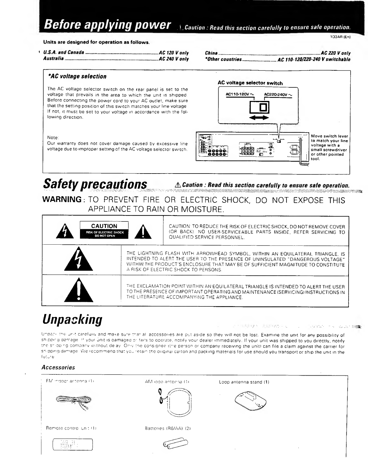
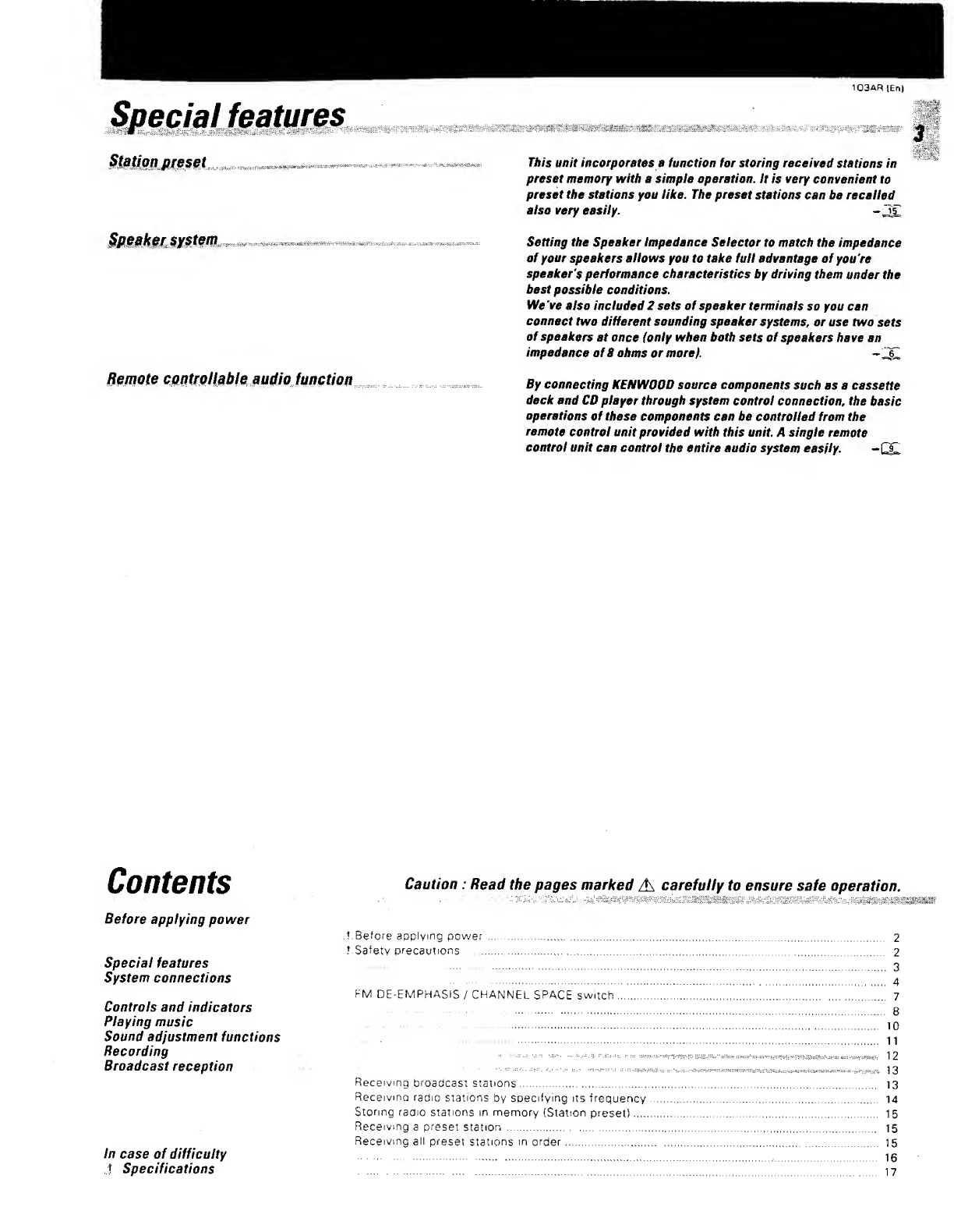
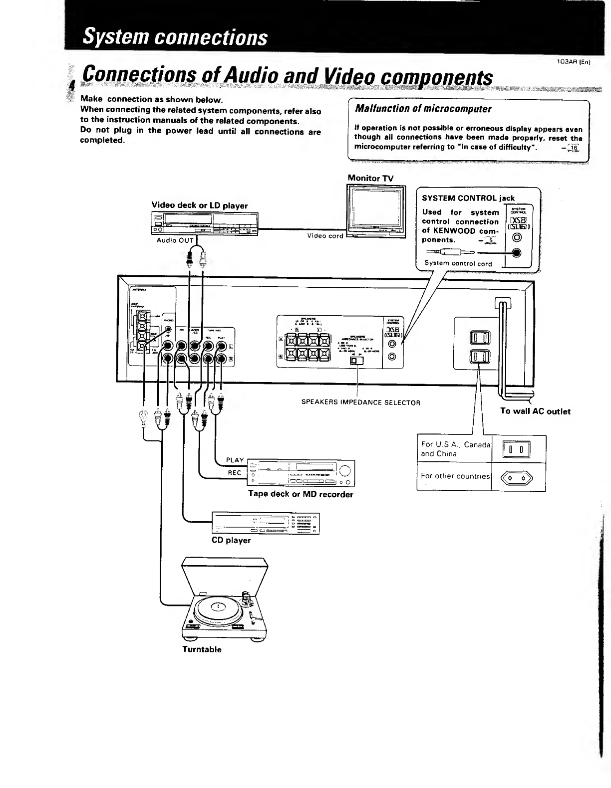
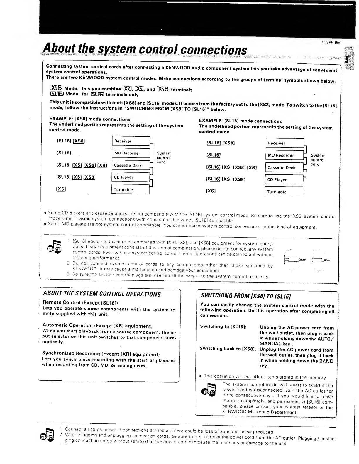
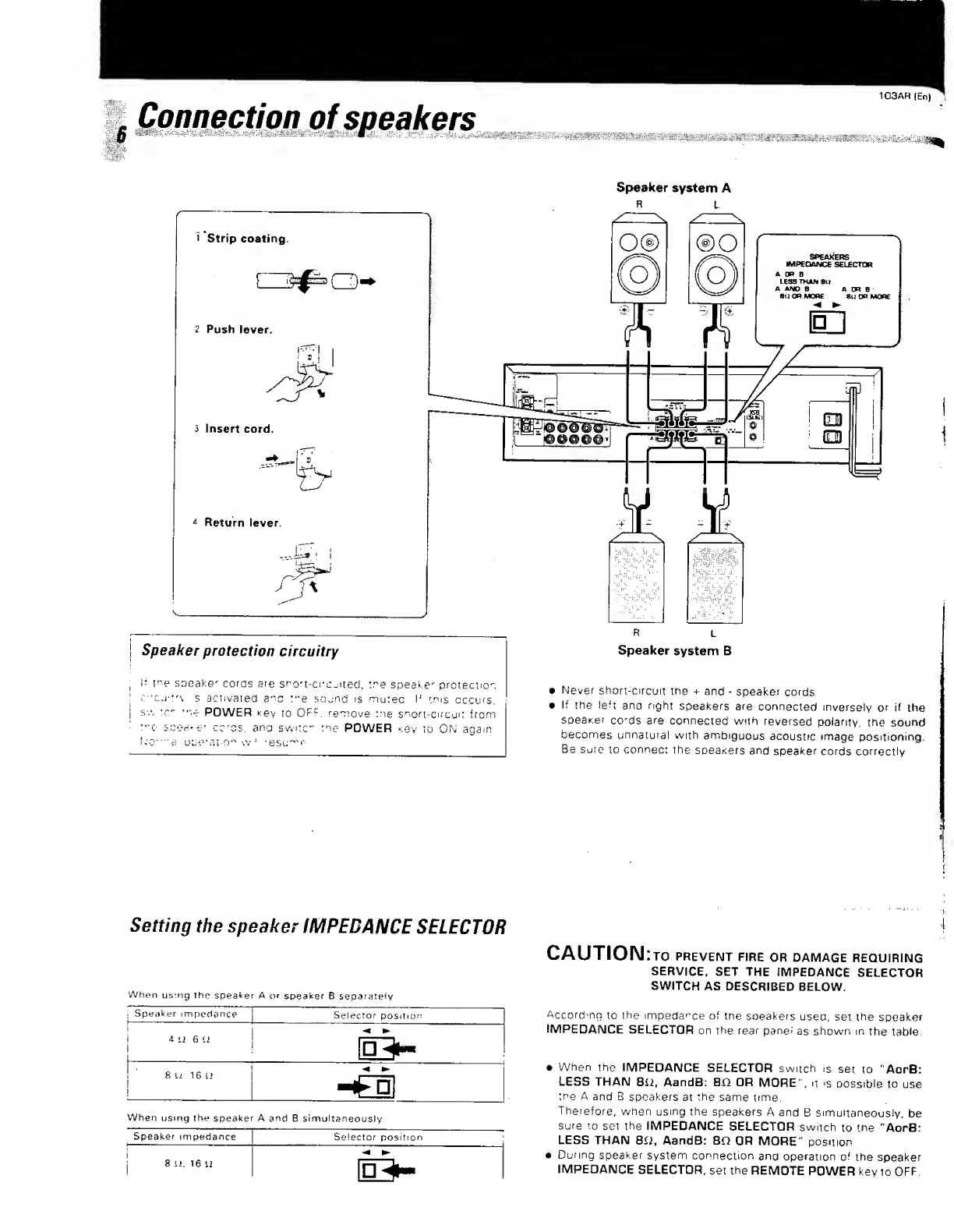
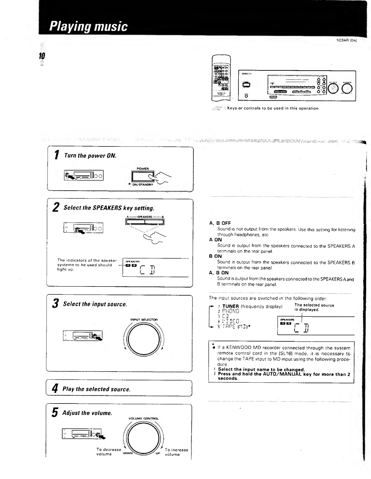
Kenwood 103AR User manual
Other Kenwood Stereo Receiver manuals

Kenwood
Kenwood Sovereign VR-5080 User manual

Kenwood
Kenwood KR-A5010 User manual

Kenwood
Kenwood 104AR User manual

Kenwood
Kenwood KR-A5520 User manual

Kenwood
Kenwood KR-V8050 User manual

Kenwood
Kenwood DVR-6200 User manual

Kenwood
Kenwood KR-710 User manual

Kenwood
Kenwood KR-4070 User manual

Kenwood
Kenwood KR-V80 User manual

Kenwood
Kenwood KRF-V4550D User manual

Kenwood
Kenwood KRC-851D User manual

Kenwood
Kenwood KR-V9020 User manual

Kenwood
Kenwood C-V351 User manual

Kenwood
Kenwood KR-7600 User manual

Kenwood
Kenwood KR-6400 User manual

Kenwood
Kenwood KRF-V7050D User manual

Kenwood
Kenwood KR-A4040 User manual

Kenwood
Kenwood KRF-V8070D User manual

Kenwood
Kenwood 106VR User manual

Kenwood
Kenwood KR-A3070 User manual


Popular Stereo Receiver manuals by other brands


Yamaha
Yamaha MusicCast TSR-5B3D owner's manual

Sony
Sony STR-DE335 - Fm Stereo/fm-am Receiver operating instructions

Sony
Sony STR-DG500 - Multi Channel Av Receiver Service manual

Panasonic
Panasonic AJSD955B - DVCPRO50 STUDIO DECK Brochure & specs

Pioneer
Pioneer SX-838 Service manual

Sherwood
Sherwood S-2660CP operation instruction