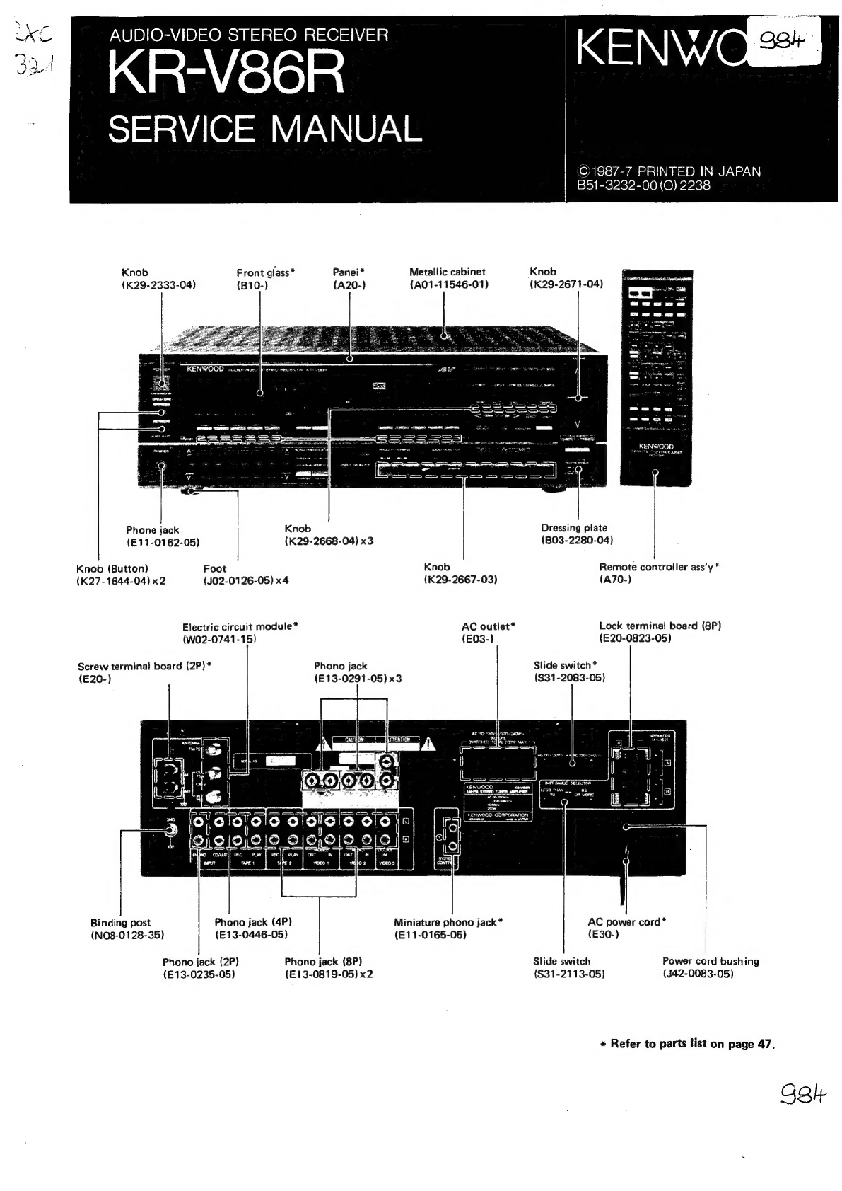
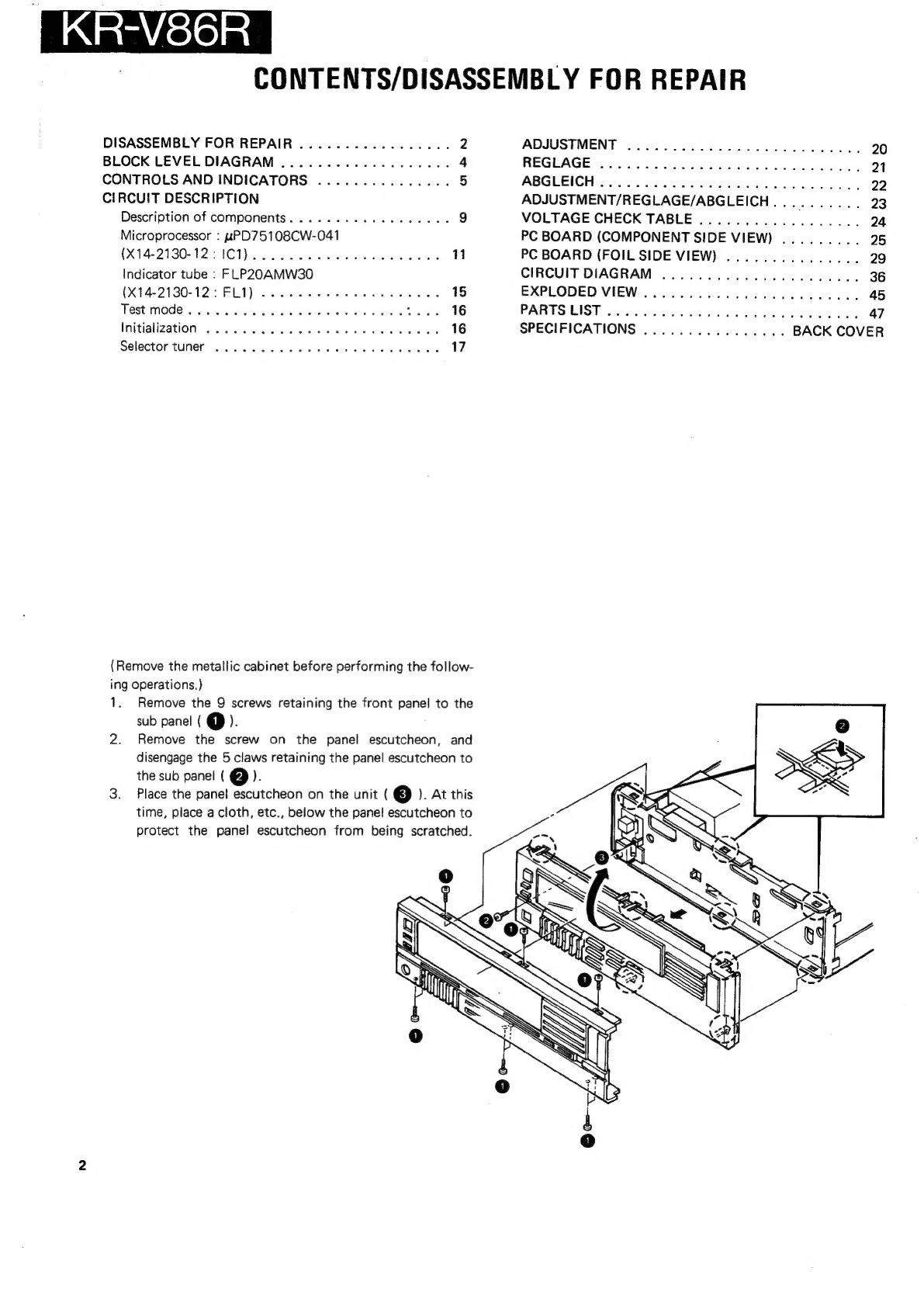
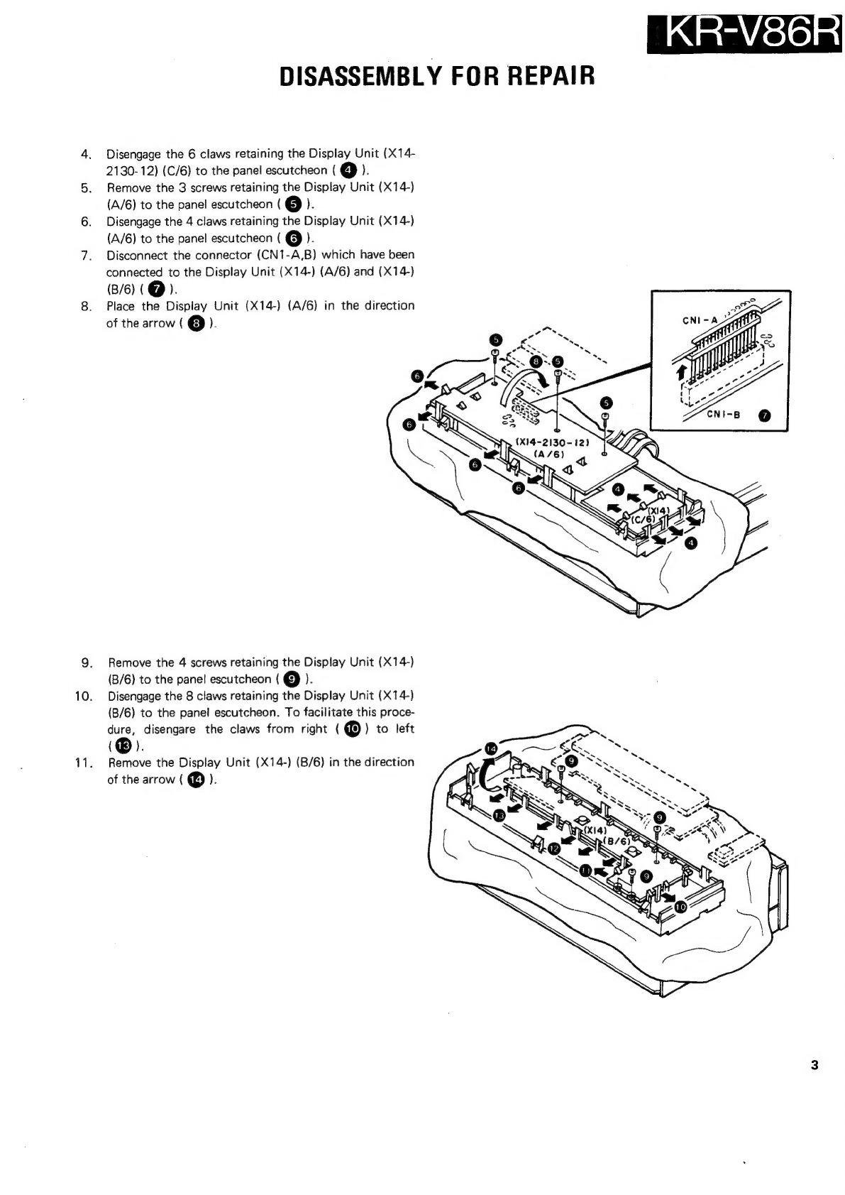
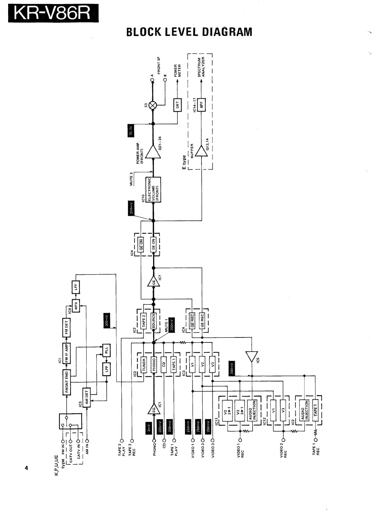
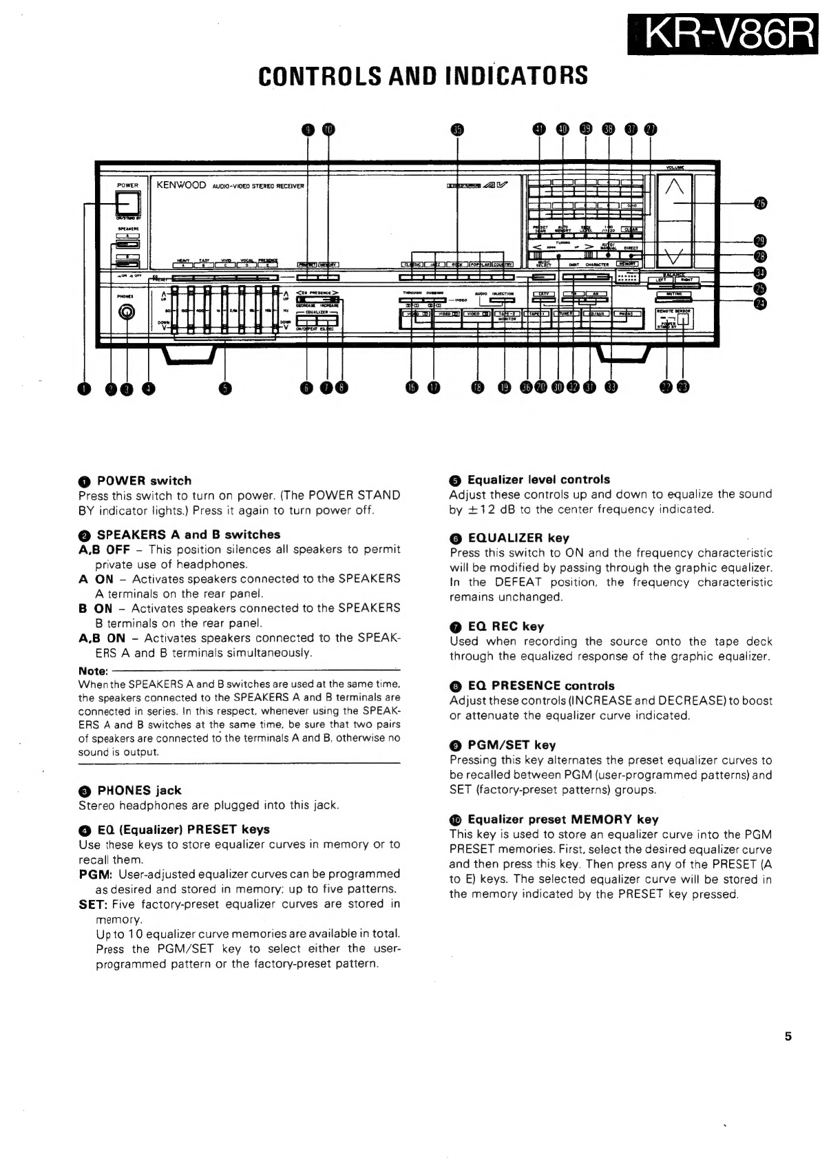
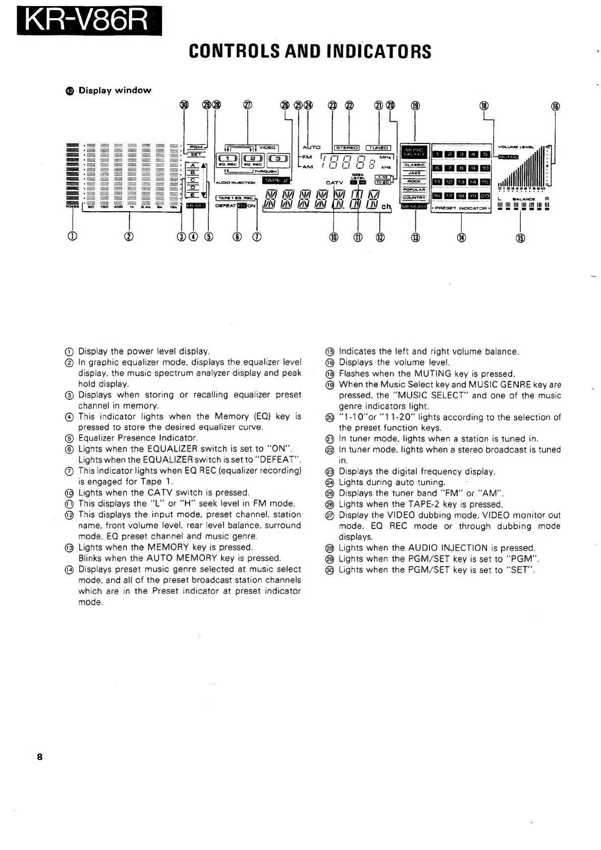
Kenwood KR-V86R User manual

ste
AUDIO-VIDEO
STEREO
RECEIVER
v
@
ap
;
SERVICE
MANUAL
‘©1987-7
PRINTED
IN
JAPAN
B51-3232-00(O)
2238
Knob
Front
glass*
Panei*
Metallic
cabinet
Knob
(K29-2333-04)
(B10-)
{A20-)
{A01-11546-01)
(K29-2671-04)
Phone
jack
Knob
Dressing
plate
(E11-0162-05)
(K29-2668-04)
x3
{BO3-2280-04)
Knob
(Button)
Foot
Knob
Remote
controller
ass’y
*
(K27-1644-04)
x2
(JO2-0126-05)
x4
(K29-2667-03)
(A70-)
Electric
circuit
module”
AC
outlet*
Lock
terminal
board
(8P)
(W02-0741-15)
(E03-)
(E20-0823-05)
Screw
terminal
board
(2P)*
Phono
jack
Slide
switch
*
(E20-)
(E13-0291-05)
x3
(S31-2083-05)
Binding
post
Phono
jack
(4P)
Miniature
phono
jack*
AC
power
cord*
(NO8-0128-35)
(E13-0446-05)
({E11-0165-05)
(E30-)
Phono
jack
(2P)
Phono
jack
(8P)
Slide
switch
Power
cord
bushing
{E13-0235-05)
({E13-0819-05)
x2
(S31-2113-05)
(J42-0083-05)
*
Refer
to
parts
list
on
page
47.
98h

KR-V86R
CONTENTS/DISASSEMBLY
FOR
REPAIR
DISASSEMBLY
FOR
REPAIR
.................
2
BLOCK
LEVEL
DIAGRAM
..................-.
4
CONTROLS
AND
INDICATORS
...............
5
CIRCUIT
DESCRIPTION
Description
of
components.
......-...02+e00es
9
Microprocessor
:
uPD75108CW-041
(X14-2130-12
ICI).
eee
eee
11
Indicator
tube
:
FLP2OAMW30
(X14-2130-12:FL1)
..
2...
ee
ee
ee
ee
eee
15
Test
MOd@
6
os
eels
vee
wie
Pa
ee
Dee
ae
ae
AG
Initialization
©...
ee
ees
16
Selector
tuner
2...
ee
ee
ee
eee
17
(Remove
the
metallic
cabinet
before
performing
the
follow-
ing
operations.)
1.
Remove
the
9
screws
retaining
the
front
panel
to
the
sub
panel
(
@P).
2.
Remove
the
screw
on
the
panel
escutcheon,
and
disengage
the
5
claws
retaining
the
panel
escutcheon
to
the
sub
panel
(
@).
3.
Place
the
panel
escutcheon
on
the
unit
(
3
]
).
At
this
time,
place
a
cloth,
etc.,
below
the
panel
escutcheon
to
protect
the
panel
escutcheon
from
being
scratched.
ADJUSTMENT
..........
0.0.00
00
cee
eee
20
REGLAGE®
3)
ie.)
eeu
ce
i
Oe
Bo
en
See
ek
21
ABGLEICH
cso
acy
Wile
a
ee
ete
eed
22
ADJUSTMENT/REGLAGE/ABGLEICH..........
23
VOLTAGE
CHECK
TABLE
...................
24
PC
BOARD
(COMPONENT
SIDE
VIEW)
.........
25
PC
BOARD
(FOIL
SIDE
VIEW)
...............
29
CIRCUIT
DIAGRAM
...................04.
36
EXPLODED
VIEW
...................
00008.
45
PARTS
LIST
oeicnun
Seatac
aod
Shey
sia
ORL
aa
47
SPECIFICATIONS
................
BACK
COVER

10.
11.
DISASSEMBLY
FOR
REPAIR
Disengage
the
6
claws
retaining
the
Display
Unit
(X14-
2130-12)
(C/6)
to
the
panel
escutcheon
(
4]
}:
Remove
the
3
screws
retaining
the
Display
Unit
(X14-)
(A/6)
to
the
panel
escutcheon
(
@
).
Disengage
the
4
claws
retaining
the
Display
Unit
(X14-)
(A/6)
to
the
panel
escutcheon
(
6)
).
Disconnect
the
connector
(CN1-A,B)
which
have
been
connected
to
the
Display
Unit
(X14-)
(A/6)
and
(X14-)
(B/6)
(
@).
Place
the
Display
Unit
(X14-)
(A/6)
in
the
direction
of
the
arrow
(
@).
Remove
the
4
screws
retaining
the
Display
Unit
(X14-)
(B/6)
to
the
panel
escutcheon
(
(9)
).
Disengage
the
8
claws
retaining
the
Display
Unit
(X14-)
(B/6)
to
the
panel
escutcheon.
To
facilitate
this
proce-
dure,
disengare
the
claws
from
right
(
®
)
to
left
(®).
Remove
the
Display
Unit
(X14-)
(B/6)
in
the
direction
of
the
arrow
(
@
).
mwisloln

KR-V86R
BLOCK
LEVEL
DIAGRAM
YAZATVN'
Vv
WNYLOAdS
Yala
Ww
YSaMOd
dS
LNOYWS
vO
dd9
L£L—-bb9l
AL
GS
(1NO¥4)
“dW
YAaMOd
€
3inWw
otol
AWOOT
Ca
wo
,
2
|
NOLLOZFNI
|
o1anv
oauY
z
O30IAN
aoe
5
=
Uoasann
|
oranv
ae
O
934
te
EA
all
4
O3GIA
i
.
~~
e
_
AWOOZ
©)
€
OJGIA
Oz
OACIA
©
1
o3dla
O
Avid
AWO0e
l |
[
no0z
|
1
adv
Eso]
Oo
l
7
=
ws
O
AW
1d
Z
advVL
ON
WY
r
O
NI
ALVS
uf
Q
LNO
ALYO
i
Seth
ONiw4s
aedAy

KR-V86R
CONTROLS
AND
INDICATORS
KENWOOD
aunio-vingo
sTeREO
RECEIVER
@
POWER
switch
Press
this
switch
to
turn
on
power.
(The
POWER
STAND
BY
indicator
lights.)
Press
it
again
to
turn
power
off.
@
SPEAKERS
A
and
B
switches
A.B
OFF
-
This
position
silences
all
speakers
to
permit
private
use
of
headphones.
A
ON
-
Activates
speakers
connected
to
the
SPEAKERS
A
terminals
on
the
rear
panel.
B
ON
-
Activates
speakers
connected
to
the
SPEAKERS
B
terminals
on
the
rear
panel.
A.B
ON
-
Activates
speakers
connected
to
the
SPEAK-
ERS
A
and
B
terminals
simultaneously.
Note:
———_——_-_-[—SS
When
the
SPEAKERS
A
and
B
switches
are
used
at
the
same
time.
the
speakers
connected
to
the
SPEAKERS
A
and
B
terminals
are
connected
in
series.
In
this
respect.
whenever
using
the
SPEAK-
ERS
A
and
B
switches
at
the
same
time.
be
sure
that
two
pairs
of
speakers
are
connected
to
the
terminals
A
and
B,
otherwise
no
sound
is
output.
@
PHONES
jack
Stereo
headphones
are
plugged
into
this
jack.
@
EQ
(Equalizer)
PRESET
keys
Use
these
keys
to
store
equalizer
curves
in
memory
or
to
recall
them.
PGM:
User-adjusted
equalizer
curves
can
be
programmed
as
desired
and
stored
in
memory:
up
to
five
patterns.
SET:
Five
factory-preset
equalizer
curves
are
stored
in
memory.
Upto
10
equalizer
curve
memories
are
available
in
total.
Press
the
PGM/SET
key
to
select
either
the
user-
programmed
pattern
or
the
factory-preset
pattern.
Pe
SSeS
siozist=
peeeese=e
==
——
=
cori
cineca
os
cee
E
alt
a
as
a
Li,
le
ae
LVI
sevect
Pe
|
oer
owe
cme
LV}
cuanacten
CHENGRT]
=e
|
Lael
©
Equalizer
level
controls
Adjust
these
controls
up
and
down
to
equalize
the
sound
by
+12
dB
to
the
center
frequency
indicated.
@
EQUALIZER
key
Press
this
switch
to
ON
and
the
frequency
characteristic
will
be
modified
by
passing
through
the
graphic
equalizer.
In
the
DEFEAT
position,
the
frequency
characteristic
remains
unchanged.
@
EQ
REC
key
Used
when
recording
the
source
onto
the
tape
deck
through
the
equalized
response
af
the
graphic
equalizer.
©
EQ
PRESENCE
controls
Adjust
these
controls
(INCREASE
and
DECREASE)
to
boost
or
attenuate
the
equalizer
curve
indicated.
©
PGM/SET
key
Pressing
this
key
alternates
the
preset
equalizer
curves
to
be
recalled
between
PGM
(user-programmed
patterns)
and
SET
(factory-preset
patterns)
groups.
@
Equalizer
preset
MEMORY
key
This
key
is
used
to
store
an
equalizer
curve
into
the
PGM
PRESET
memories.
First,
select
the
desired
equalizer
curve
and
then
press
this
key.
Then
press
any
of
the
PRESET
(A
to
E)
keys.
The
selected
equalizer
curve
will
be
stored
in
the
memory
indicated
by
the
PRESET
key
pressed.

KR-V86R
CONTROLS
AND
INDICATORS
@
THROUGH
DUBBING
[2]
>
[1]
key
This
activate
the
through
dubbing
from
VIDEO
2
to
VIDEO
Te
@
THROUGH
DUBBING
[3]
>
[1]
key
This
activate
the
through
dubbing
from
VIDEO
3
to
VIDEO
1.
Note:
——___________-—-______—_——_.
Pressing
the
THROUGH
DUBBING
key
twice
will
resume
the
previous
mode.
@®
Input
selector
switches
VIDEO
1
—
Selects
the
video
recorders
connected
to
the
VIDEO
1
jacks.
VIDEO
2
-
Select
the
video
recorders
connected
to
the
VIDEO
2
jacks.
VIDEO
3
-
Select
the
video
recorders
connected
to
the
VIDEO
3
jacks.
TAPE
1
—
Press
this
switch
to
play
back
a
tape
deck
connected
to
TAPE
1
jacks.
TAPE
2
-
Press
this
switch
to
play
back
a
tape
deck
connected
to
the
TAPE
2
jacks.
(The
TAPE-2
switch
is
Operated
in
priority
to
any
other
audio
input
systems.)
TUNER
-
Selects
the
tuner
mode.
CD/AUX
-
Selects
the
source
connected
to
the
CD/AUX
jacks.
PHONO
-
Selects
the
program
source
played
on
the
turntable.
@
AUDIO
INJECTION
switch
Press
this
switch
ON
when
replacing
the
sound
of
VIDEO
1,
2
with
that
of
AUDIO
source.
or
when
the
sound
equalized
by
graphic
equalizer
is
required
on
dubbing
between
VIDEO
sources.
@
CATV
ON/OFF
switch
Press
this
switch
to
select
FM
759
or
CATV
7529
antenna
line.
@
REMOTE
POWER
STAND
BY
indicator
This
indicator
lights
so
far
as
the
power
cord
is
plugged
into
the
AC
outlet.
It
is
lit
to
show
that
the
POWER
switch
on
the
front
panel
or
the
POWER
key
on
the
remote
control
unit
can
be
activated.
@
REMOTE
SENSOR
Point
the
supplied
remote
control
unit
towards
this
sensor
and
operate.
It
blinks
when
the
signal
from
the
remote
control
unit
is
received.
@
MUTING
key
When
the
muting
key
is
pressed,
the
MUTING
indicator
in
the
display
window
will
flash,
and
the
overall
listening
sound
level
is
reduced.
When
the
key
is
pressed
again,
you
can
restore
exactly
the
same
listening
level
as
before.
@
BALANCE
controls
Governs
the
amount
of
sound
coming
from
each
paired
speakers
to
get
optimum
stereo
effect.
Pressing
the
RIGHT
key
will
decrease
the
left
channel
volume
and
pressing
the
LEFT
key
will
decrease
the
right
channel
volume.
When
the
BALANCE
controls
is
pressed,
display
window
shows
the
BALANCE
indicator.
@
VOLUME
controls
This
control
adjusts
the
left-
and
right-channel
volumes
simultaneously.
Set
it
for
the
desired
listening
level.
Pressing
the
up
(A)
key
increases
the
volume
and
pressing
the
down
(V)
key
decreases
it.
Note:
———--—_£.
TT
_iiuc——
A
slight
noise
is
heard
from
the
speakers
when
operating
the
VOLUME
controls.
This
noise
is
the
built-in
microprocessor
control
signal
and
is
not
a
fault.
@
Preset
(numeric)
keys
Use
these
keys
to:
1)
input
directly
the
digits
of
frequencies,
or
2)
store
and
recall
frequencies
in
the
preset
memory.
@
DIRECT
key
Used
to
tune
to
the
station
directly.
Input
the
desired
frequency
numerics
with
the
numeric
keys
after
pressing
the
DIRECT
key.

KR-V86R
CONTROLS
AND
INDICATORS
@
AUTO/MANUAL
(MONO)
key
When
this
key
is
pressed,
the
AUTO
indicator
will
light.
The
frequency
will
automatically
stop
at
a
station
in
automatic
tuning
mode.
When
a
stereo
broadcast
is
received,
the
Output
sound
is
automatically
changed
to
stereo.
@
TUNING
key
Used
to
change
the
frequency.
Pressing
UP
side
will
advance
to
the
higher
frequency
and
pressing
DOWN
side
to
the
lower
frequency.
In
the
station
name
input
mode,
this
key
is
used
to
select
the
character.
@
BAND
selector
switches
FM
-
For
FM
broadcasts.
AM
-
For
AM
broadcasts.
@
DIGIT
SELECT
key
In
the
station
name
input
mode,
pressing
this
key
advances
the
column
after
selecting
the
character
with
the
Tuning
UP/DOWN
key.
When
this
operation
is
repeated
four
time,
the
station
name
input
mode
will
be
released
automatically.
@
CHARACTER
MODE
key
Press
this
key
to
activate
the
station
name
input
mode.
@
MEMORY
key
When
the
input
mode
is
tuner
mode,
use
this
button
to
store
new
broudcast
station
data
in
the
preset
channel
memory.
By
pressing
the
MEMORY
key,
setting
the
preset
function
key
to
1-10
or
11-20
and
by
pressing
one
of
the
PRESET
10
key,
the
frequency
being
received
is
stored
in
the
memory
in
the
preset
10
key
pressed.
€@
MUSIC
SELECT
key
Pressing
this
key
alternates
between
the
Music
Select
mode
and
the
Preset
indicator
mode.
@
MUSIC
genre
key
In
the
Preset
indicator
mode,
a
desired
music
genre
can
be
stored
into
each
Preset
Channel
memory
button.
In
the
Music
select
mode,
this
key
is
also
used
to
select
the
music
genre.
@
CLEAR
key
Used
to
clear
the
contents
stored
in
the
preset
channel
memory.
After
recalling
the
preset
channel
to
be
cleared,
pressing
this
key
will
clear
the
memorized
contents.
@
Preset
function
(1-10/11-20)
key
Used
to
select
1-10
or
11-20
setting
for
the
preset
channel
key.
In
either
FM
or
AM
mode,
20
stations
can
be
preset
as
random
as
each
setting
(“
1-10”
or
11-20")
can
contain
10
preset
stations.
Indicator
"1-10"
lights
when
“1-10”
setting
is
used,
and
indicator
“11-20”
lights
when
“11-20”
setting
is
used.
@
SEEK
LEVEL
select
key
(During
FM
reception
only)
Used
to
select
the
stop
level.
When
‘’L”
is
selected,
the
Auto
Stop
and
Auto
Memory
functions
are
possible
even
for
the
weak-signal
stations.
When
‘‘H”
is
selected,
the
Auto
Stop/Auto
Memory
functions
are
performed
only
for
the
stations
having
strong
signal.
Pressing
this
key
alter-
nates
between
“L”
and
“H”.
@
AUTO
MEMORY
key
When
this
key
is
pressed
ON,
the
station
frequencies
will
be
scanned
and
stored
into
the
Preset
Channels
automati-
cally.
Scanning
operation
is
performed
from
the
displayed
frequency
to
the
higher
range
and
finished
after
one
cycle
is
Over
with
the
receiving
band.
During
Auto
Memory
operation,
the
Memory
indicator
blinks.
To
release
it.
press
the
AUTO
MEMORY
key
again.
@
PRESET
SCAN
key
Use
this
key
for
preset
channel
scanning.
When
a
frequency
stored
in
the
preset
memory
is
being
received,
pressing
this
key
shifts
the
reception
to
the
next
frequency
stored
in
the
preset
memory.
(The
preset
channels
are
scanned
in
the
order
1,
2......
Vite
U2
sec
20,)
When
frequencies
other
than
those
stored
in
the
preset
memory
received,
pressing
this
key
changes
the
reception
to
the
frequency
in
preset
channel
1.
@
Tostop
ascanning
operation,
press
the
SCAN
key
again.
@
In
MUSIC
SELECT
mode,
a
preset
scanning
operation
is
performed
within
the
music
genre
selected.

KR-V86R
CONTROLS
AND
INDICATORS
@
Display
window
Colca
vIpEo
AUDIO
INJECTION
:
°
@
Display
the
power
level
display.
@®
In
graphic
equalizer
mode,
displays
the
equalizer
level
display,
the
music
spectrum
analyzer
display
and
peak
hold
display.
@
Displays
when
storing
or
recalling
equalizer
preset
channel
in
memory.
@
This
indicator
lights
when
the
Memory
(EQ)
key
is
pressed
to
store
the
desired
equalizer
curve.
®
Equalizer
Presence
Indicator.
©
Lights
when
the
EQUALIZER
switch
is
set
to
“ON”.
Lights
when
the
EQUALIZER
switch
is
set
to
“DEFEAT”.
@)
This
indicator
lights
when
EQ
REC
(equalizer
recording)
is
engaged
for
Tape
1.
@
Lights
when
the
CATV
switch
is
pressed.
@
This
displays
the
‘’L”
or
“H”
seek
level
in
FM
mode.
@
This
displays
the
input
mode,
preset
channel,
station
name.
front
volume
level,
rear
level
balance,
surround
mode,
EQ
preset
channel
and
music
genre.
@
Lights
when
the
MEMORY
key
is
pressed.
Blinks
when
the
AUTO
MEMORY
key
is
pressed.
Displays
preset
music
genre
selected
at
music
select
mode,
and
all
of
the
preset
broadcast
station
channels
which
are
in
the
Preset
indicator
at
preset
indicator
mode.
VOLUME
LEVEL
y
y..
STEREO
TUNED
@
Indicates
the
left
and
right
volume
balance.
@®
Displays
the
volume
level.
@
Flashes
when
the
MUTING
key
is
pressed.
When
the
Music
Select
key
and
MUSIC
GENRE
key
are
pressed,
the
“MUSIC
SELECT”
and
one
of
the
music
genre
indicators
light.
@
“1-10"or
“11-20”
lights
according
to
the
selection
of
the
preset
function
keys.
@)
In
tuner
mode,
lights
when
a
station
is
tuned
in.
@
In
tuner
mode,
lights
when
a
stereo
broadcast
is
tuned
in.
@
Displays
the
digital
frequency
display.
Lights
during
auto
tuning.
@
Displays
the
tuner
band
“FM”
or
“AM”.
@
Lights
when
the
TAPE-2
key
is
pressed.
@)
Display
the
VIDEO
dubbing
mode,
VIDEO
monitor
out
mode,
EQ
REC
mode
or
through
dubbing
mode
displays.
@
Lights
when
the
AUDIO
INJECTION
is
pressed.
@)
Lights
when
the
PGM/SET
key
is
set
to
“PGM”.
@
Lights
when
the
PGM/SET
key
is
set
to
“SET”.

KR-V86R
CIRCUIT
DESCRIPTION
Description
of
components
TUNER
UNIT
(X05-3330-12)
Pict
fFwiFdemor
CCS
\C2__|
PLL
(phase-lockedioopi
___—+|SSSCSCSCSCSCSSCSSS
a
IC4
FM
MPX
7
Q5
FM
+
B
select
Turns
ON
in
FM
mode.
Q6
AM
+B
select
Turns
ON
in
AM
mode.
Q7
FM
+
B
select
Turns
ON
in
FM
mode.
Q8
TUNED
indicator,
for
SD
Turns
OFF
when
tuned.
ag
Forced
mono
select
Turns
OFF
in
forced
mono
mode.
TUNED
indicator,
for
SD
Turns
ON
when
tuned.
Forced
mono
select
Turns
ON
in
forced
mono
mode.
CATV
relay
drive
Turns
ON
in
CATV
mode.
Q14,
15
Seek
level
select
Q15
is
ON
and
Q14
is
OFF
when
low.
Q16
Buffer
for
LS
+
B
ripple
filter
Microcomputer
(4-COM)
power
supply,
20
for
fast
OFF
MAIN
AMPLIFIER
UNIT
(X07-2350-
12)
Component
Use/
Function
Operation/Condition/Compatibility
Ic1
Protection
Relay
drive.
ai=4
|
Prmarystgevelapaniieetien
|
|
ara~16
|
Third
stops
vottoge
amplification
|
_________—S
aai~24
|
Power
amplifier
drive
|
Q27,
28
Protection,
current
detection
Negative
(—)
side.
Q29
Transmits
the
current
detected
signal
to
1C1.

10
AUDIO
UNIT
IC4
1C5
IC6
:
’
(X09-2470-
12)
Use/
Function
Phono
equalizer
1C2,3
Input
selector
select
GE,
GE
REC
ON/OFF,
surround
mode
select
Buffer
for
REC
CIRCUIT
DESCRIPTION
Operation/Condition/Compatibility
ai
|
ice.
VR
array
for
GE
(graphic
equalizer)
1C7,8
Op
amplifier
for
GE
(graphic
equalizer)
Semiconductor
L
(self-reactance)
x
7.
For
front
channel.
Muting
when
changing
the
selector.
Q9
and
Q10
are
driven
by
open
collector.
Emitter
follower.
Muting
for
MAIN
IN
section.
Switch
for
—33V,
high-8
(beta)
transistor.
Inverted-darlington
connection
with
Q32.
Error
amplification.
1C10
Electronic
volume
C12
3-pin
regulator
15V.
Muting
Q11
Q13,
14
Land
R
mixer
for
apectrum
analyzer
Q17,18
Muting
Q19,
20
Drive
circuit
for
muting
Q25
Constant
voitage
for
—33V
Q27
For
FL
ON
(go
on)
timing
Q28
Q29
For
FL
OFF
(go
out)
on
power
OFF
Q30
For
—14V
constant
voltage
Q31
—14V
constant
voltage
Q32
—14V
constant
voltage
Q33
5V
constant
voltage
Q34
5V
constant
voltage
Q37,
38
For
main
amplifier
bias
DISPLAY
UNIT
(X14-2130-
12)
Q39~42
Main
amplifier
final
stage
5V
power
supply
for
display.
5V
power
supply
for
u-COM
(microcomputer).
Component
Use/
Function
Operation/Condition/Compatibility
{C1
1C8,9
1C10,
11
IC12,
13
1C14~17
(2/2)
1017
(1/2)
Mierocomputer
ee
ee
Transistor
array
(for
FL
drive)
Active
low.
GE,
SP
display
IC
Logic
IC
Static
driver
(for
FL
drive)
Transistor
array
(for
FL
drive)
Active
high.
Data
mute
circuit.
Analog
switch
IC
Spectrum
analyzer
band-pass
filter
Spectrum
analyzer
band-pass
filter
Qi~4
Q7
Q8~10
Qi1
Digital
transistor
(for
FL
drive)
Video
select.
|
an
Input
amplifier.
ea
For
through-dubbing
control
Turns
OFF
when
a
through-dubbing
operation
is
activated
in
VIDEO
2
and
VIDEO
3
mode.
Data
mute
circuit
Video
output
buffer
Q12,
13
a14
Realy
drive
Microcomputer
reset
circuit
ania
Turns
ON
for
several
milli-seconds,
when
power
is
turned
ON.

KR-V86R
CIRCUIT
DESCRIPTION
Microprocessor
:
.PD75108CW-041
(X14-2130-
12
:
IC1)
*1:K,P,U
&
UE
types
only.
*2:
E
type
only.
Terminal
connection
PIZ/INTS
PA2ANT2
PIV/INTT
PIOHNTO
PTHO3
PTHO2
PTHO1
PTHOO
5D
Volume
Speed
H/L
Remocon
Signal
Key
Input
Key
Input
Key
input
Key
Input
MUTE1
LC7565
CLK
MUTE3
Initial
Switch
P21/PTO1
P20/PTOO
PO3/SI
PO2/SO
POI/SCK
POO/INTS
Key
Input
Key
input
Key
Input
Key
Input
Volume
IC
(CX7978)
ST
Switch
IC
{TC9162,
63,
64)
ST
PLL
IC
(LM7001)
CE
Static
Driver
(4PD6300C)
LH
EQ.
IC
(LC7522)
ST
ALL
IC
CLK
ALL
IC
DATA
Remocon
Received
LED
;
EQ.
ON/
:
DEFEAT
La
;
;
/
400Hz
400Hz
;
:
:
—
DOWN
i
UP
;
(a3)
@
.
.
&
e
o:
oat
4
ANCE
ANCE
L
R
L\
Ls £\
L\
L\
Ly
Ly
MUSIC
SPEC-
TYP!
TYP2
TEST
JBANO
TRUM
YES
NO:
YES
NO}
NO
YES}
NO
YE!
i?)
Q
1
0
1
C1)
PO2
PHTOO
(16)
(8)
©
Volume
IC
CX7978
@
PLL
IC
LM7001
CLK
(9),
DATA
(10),
ST
(11)
CLK
(2),
DATA
(4),
ST
(3)
CS1
(4)
CS2
{5)
M/S
(6)
Vss
Vss
OPEN
or
VDL
REAR
|
OPEN
or
VOL
|
OPEN
or
VDL
|
OPEN
or
VDL
The
ST
signal
to
the
IC
is
input
by
differentiating
the
signal
from
the
microcomputer.
@
Switch
IC
CLK
(15),
DATA
(16),
ST
(13)
$1
Ss?
$8
TC9162N
EQ
REC
EQ
REC
EQ ON
THEATER
STADIUM
_
|
_
VIDEO
2
VIDEO
3
AUDIO
TC9163N
2-1
3-1
INJECTION
1
VIDEO
1
VIDEO
2
VIDEO
3
(V1
REC}
(V1
REC)
{V1
REC)
To
FL.
al
d|
al
al
al
al
ai
8
Sl
POWER
Serial
BUSY
Serial
OATA
x
[kr-vi2eR|
1 | 0
|
[kr.viogR
|
0
|
1
_|
[krvesr
|
o
|
0
|
1:
Diode
used
0:
Diode
not
used
VIDEO
1
VIDEO
3
(V2
REC)
(V2
REC)
AUDIO
TC9164N
TAPE
1
CD/AUX
PHONO
TAPE
2
PLAY
|
TAPE
2
PLAY
|
INJECTION
2
(V2
REC)
The
ST
signal
to
the
IC
is
input
differentiating
the
signal
from
the
microcomputer.
©
Static
Driver
{C
uPD6300C
CLK
(12),
DATA
(71),
LH
(10)
[
Output
|
00
(15)
02
(17)
o3(18)
|
oaig)
|
05120)
06
(21)
07
(22)
08
(23)
09
(24)
mn
EEK
PDS
PO2
POI
PCé
13
(1)
010
(25)
011
(26)
|
012(27)
014
(2)
015
(3)
016
(4)
017
(5)
018
(6)
019
(7)
AUDIO
INJECTION
M
Terminal
PC4
PC1
PC3.
PC5
Dispaly
EQON
|SURROUND!
TAPE2
‘
=)
@
Equalizer
IC
LC7522
S
(13):
VEE,
CLK
(17),
DATA
(16)
11
©
EQ./SPI
dispaly
IC
LC7565
$1
(15),
S2
(16)
:
VoD,
CLK
(18),
DATA
(17)

KR-V86R
CIRCUIT
DESCRIPTION
Terminal
functions
V0
Name
=
Backup
detection
pin.
:
PASANTS
ce
When
this
goes
low
level,
backup
mode
is
set
and
the
clock
stops.
Description
Station
presence/absence
detection
signal
input
pin:
Used
in
Auto
Tuning,
Auto
Memory,
and
Preset
Scan.
High
:
station
is
not
present,
Low
:
Station
is
present.
PI2/AINT2
Volume
data
output
inhibition
time
setting
port
:
Used
when
electronic
volume
CX7978
Volume
Speed
malfunctions
at
low
temperature.
High
:
400ms,
Low
:
96ms.
*
This
is
used
when
low
in
the
KR-V126R.
Remote
control
signal
input
pin
after
detection
:
Inputs
the
remote
control
signal
level
in
normal
mode
and
when
reading
out
the
leader
code.
Detects
the
signal
by
interruption
the
rising
edge
when
reading
the
data.
PII/INT1
Remocon
Signal
PIO/INTO
Key
matrix
return
signal
input
pin
:
Normally
high.
(Threshold
voltage
=
VDD
x
7.5/16,
Conversion
time
:
32.3us).
Not
used
No-connection
input
pin.
Fixed
at
VDD
or
Vss.
Muting
signal
output
pin
:
Used
when
the
Input
Selector
is
changed,
during
tuning
scan,
P23
etc.
Normally
low,
Active
high.
MUTE1
(CMOS)
P22/PCL
Output
pin
to
be
connected
to
the
CLK
pin
of
LC7565.
Normally
low.
(CMOS)
@
With
the
volume
level
of
the
front
channel
set
to
between
0
and
—28dB,
outputs
the
13
P21/PTO!
oO
MUTE3
muting
signal
for
a
short
period
(about
10msec.)
when
the
TAPE2
ON/OFF,
EQ
ON/
(CMOS)
OFF,
EQ
REC
ON/OFF,
surround
ON/OFF
or
surround
mode
selector
is
switched.
@
When
the
volume
level
of
the
front
channel!
is
set
to
—
aB,
outputs
the
muting
signal.
14
P20/PTOO
ie)
Initial
Strobe
signal
for
taking
in
the
initial
switch.
(CMOS)
SW
Momentarily
low
immediately
after
reset,
otherwise
always
high.
PO3/SI~
Key
Key
matrix
returns
signal
input
pin
:
15~18
I
POO/INT4
Normally
high.
;
©
ST
signal
output
pin
for
the
electronic
volume
IC
(CX7978)
.
@
Normally
high,
and
tow
when
data
is
output.
@
The
microprocessor
signal
is
input
to
the
ST
pin
of
CX7978
after
differentiating.
Nch
Volume
IC
(CX7978)ST
P123
Switch
IC
N
ch
(TC9162N,
9163N,
9164N)ST
©
ST
signal
output
pin
for
the
switch
ICs
(TC9162N,
TC9163N.
amd
TC9164N).
@
Normaily
high,
and
}ow
when
data
is
output.
@
The
microprocessor
signa!
is
input
to
the
ST
pin
after
differentiating.
PLLIC
(LM7001)CE
@
CE
signal
output
pin
for
the
PLL
IC
{LM7001)
.
@
Normally
tow,
and
high
when
data
is
output.
@
LH
signal
output
pin
for
the
Static
Driver
IC
(uPD6300C)
.
@
Normally
tow,
and
high
when
data
is
output.
Static
Driver
open
(uPD6300C)
LH
©
The
signal
pin
used
to
mute
the
CLK
and
DATA
signals
to
the
other
ICs,
so
that
the
signal
is
not
input
to
the
CLK
and
DATA
pins
of
LC7522.
@
Normally
high,
and
low
when
data
is
output.
EQIC
(LC7522)ST
©
CLK
signal
output
pin
for
CX7978,
TC9162N,
TC9163N,
TC9164N,
LM7001,
AND
LC7522,
@
DATA
signal
output
pin
for
CX7978,
TC9162N,
TC9163N,
TC9164N,
LM7001,
C7522,
and
LC7565.
Remocon
Received
LED
Directly
drives
the
remote
control
STANDBY/RECEIVED
LED.
\t
blinks
while
the
remote
control
signal
is
being
received,
and
is
lit
otherwise.
12

open
|
drain
1/0
(CMOS)
ie)
(CMOS)
ie)
(CMOS)
ce)
(CMOS)
CIR
CUIT
DESCRIPTION
@
FL
segment
control
pin.
@
Negative
logic.
e
Drives
the
FL
display
through
an
inversion
buffer.
‘
Power
supply
pin.
Serial
DATA
@
DATA
pin
for
system
serial
communication
.
@
Normally
in
input
mode,
and
in
output
mode
only
when
serial
data
is
output.
e@
BUSY
pin
for
system
serial
communication
.
@
Normally
in
input
mode.
Outputs
a
high
level
signal
when
serial
data
is
output..
Also
provides
the
serial
bus
control
function.
Output
pin
for
the
power
relay
control
:
Active
high.
This
is
controlled
by
the
POWER
key.
It
alternates
between
high
(Power
ON)
and
low
(Power
OFF)
each
time
the
POWER
key
is
pressed.
@
FL
digit
contro!
pin.
@
Negative
logic.
@
Drives
the
FL
display
through
an
inversion
buffer.
Input
pin
for
the
reset
signal
from
the
microcomputer
.
@
System
clock
osciflator
pin
(4.194MHz)
.
@
FL
segment
control
pin
.
®@
Negative
logic.
@
Drives
the
FL
display
through
an
inversion
buffer.
@
Key
intake
strobe
signal
output
pin.
9g
P
CT
13

KR-V86R
CIRCUIT
DESCRIPTION
Biock
diagram
BIT
SEQ.
ae)
BUFFER(16)
(|
Porto
(4
|
POO—P03
(—}
port:
Ka
]Pi0-ps
=)
porT2
{4
)
P20-p23
—_
PORT3
|
4_)
P30-P33
BASIC
INTERVAL
TIMER
PROGRAM
INTBT
COUNTER
(13)
TIOO
TIMER/EVENT
COUNTER
PTOO/P20
O
#0
INTTO
Tho
TIMER/EVENT
COUNTER
GENERAL
REG.
PTO1/P210
Pan
ROM
oS
PORT
4
(4)
P40—P43
INTT1
PROGRAM
(Nort
|
5
(4)
PS0—P53
S1/P03
0
DECODE
$0/P02
0
Serer
tical
AND
Keo
INTERE
AGE
8064X8
BITS
CONTROL.
DATA
MEMORY
2
PoRT6
K
4
)P60—Pé3
Blend
elts
ait
Pont7
|
4
)P70-P73
INTO/P10
©
(__}
Ports
_
4
)Peo-ras
1/P
NEUEN
INTERRUPT
(~\
INT2/P12
0
(__}
eorts
{4
)
Poo-res
INT3/P13
©
ea
fx/2N
INT4/P00,0
=)
(4
)
P1201
pastas
cLock
|
clock
STAND
BY
es
—
oo
:
ry
ieee
ea
OuTPUT
|
oiviverR
|
GENERATOR
|
CONTROL
pres
PTHOO—PTHO3
[a
ABLE
CONTROL
port
13
{4
)
P190—
THRESHOLD
PORT
#0
!
t
|
$
ot
PCL/P22
x2.
x4
Vop
Vss
RESET
eae
FE
14

15
*(PpseOg
Dd
BY)
UO)
Ajjeuse1xXa
pa}DaUUOD
aq
isn
Aay}
‘Aejdsip
74
ay
apISU!
PayauUOD
JOU
ale
,,¥,,
pue
’,
6
snes
u
‘l,,
SpuawBas
ayt
aoulg
te
aaber
Wee
Ulg
paaauUoZ|
Ajjeusazuy
:
2
PHD
:
7
epouy
-
WUBWe|t4
:
Se}0N
Md
|
Ma]
a
|
or
|
be
|
oz
|
ld
EERIE
a
6e
|
es
|
ae
|
oe
|
se
|
ve
|
ee
18
“ON
[euluaL
ai
(Nd
(Wd
]
(Yd
|
(%d
9E
(d)d
|
(dja
ov
(4d
(thd
|
(W)d
ee
ee
eee
eee
racia
[oe
a
facie
was
es
|
oe
we
(G0)
jars
[ward
|
98
[Teata
[96
[Wola
[crore
[tro
[Toto
(vO)d
|
(ED)d
DI}
(ZO)d
|
(Sd
|
DOL
|
(LO)d
|
(ZAG
|
(Lad
|
OLE
|
(vV)d
[(T1VW)}d]}
Oet
al
ae
ee
ae
eo
Lone
OSL
|
(6W)d
|
(8V)d
|
D9t
|
(ZV)d
|
(9V)d
|
DLE
|
(SW)d
|
(EV)d
|
OBL
|
(ZV)
|
(LV
)d
Pappa
ppope
te
tet
et
ey
ee
apos}9a}3
ag
©
00
7
Cr
<<
“ON
[eulule
9pos198/9
“ON
(eU]Usi8f
9podyo3|3
“ON
[eulwWsaL
apo.1j98}3
=.
“ON
JeulwaL
os]
—_
Pp Pp
pas
=
ME
NEL
W
VET
NE,
WA
IW
i
ce
oop
aD
.
-_
--
=
A
Re
21
1AM
LAN
LAN
ANI:
“
=
.
Lid
amma]
=
_
=
sb
d
jo
uw
nv
d
I01Ww
ss
*BOLVOION!
LESS
*|
ITEM
——s
—
—
—
SE
5250)
RTE
PINT]
AON
WA
NM]
WA
WW.
Lae
=>
9
*
(iS
Ks
I
a
|
IN
iM
ce
8
{i
ee
aoe
[le
mE
xo
a
ceases
‘
4
Po
zzvwe
1
;
o—fRanogHa]
=
17
‘
a
é
BaoaAae
SISTA
hs
nyt
uP
nal
Gepaleh
Is
WY
aT
x
:
Loa
as
ZIUN
els
aa
1xh
Is
A
~—
[6
Seite
[aanne
]
(esas)
oinv
8
By
bo
a
=
=
9t
92
9€
op
9S
oL
|
98 9b
901
oi
|ozt
{oer
|
ov
|
ogi
|
oor]
ozt
|
ogi
i=)
N
swe
ee
ee
|
OLVOICNI
.
nr
ei
hurt!
lod
na7l
|
heal
|
iA
F
elQEl
al
oe
STi
fh
ff]
“o'r
OON
Somes
mmm
4
ATF
/
NT
N07
|
|
|
|
S=25
|
CSE
=
“
semass
||
ALL)
AN
IAN
IANA
IAN
Casmreumney
|
4
=|:
=
g
°
=——-
(oe
an
ALWO
an
©
fe
3avi
|
NoOILoarNI
O1lanyv
,
=.
=
*
_2zve
HenoeHL—
:
SB}.
——
5
eS
Sisewaa
|
ZHH
my cl
7
WY
;
-
Vv
:
=
&
:
SNL
TA)
perme
eft
(Ij 1_!
Wa
<ss-
|:
=>
ee
|
eee
SM
fess)
|(omams)||
ounv
|)
[oso
fly
|
Shoe:
=
i=

KR-V86R
16
CIRCUIT
DESCRIPTION
Test
mode
(1)
Setup
and
release
of
test
mode
Setup
:Apply
test
mode
diode
and
reset
the
micro-
processor.
In
actual
sets,
short-circuit
the
test
mode
set
pins.
Release
:
Without
the
test
mode
diode,
reset
the
micro-
processor.
In
actual
sets,
open
the
test
mode
set
(2)
Contents
of
test
mode
®
Volume
Up/Down
operation
The
operation
attenuation
level
can
be
set
at
3
points;
OdB,
—28dB,
and
—eodB.
Balance
operation
Operation
mode
can
be
set
at
3
points;
L,
center,
and
R.
:
E
type
AM_
531kHz
AM_
630kHz
AM
990kHz
AM
1440kHz
AM
1602kHz
an
@
EQ
(Equalizer)
Up/Down
operation
.
The
operation
level
can
be
set
at
3
points;
+
12dB,
OdB,
and
—12dB
for
each
frequency
band.
@
Setting
of
the
tuner
adjustment
frequency.
Preset
chant
|
————
Contes
——_]
Preset
channel
Preset
channel
|
1__—=s[
FM_87.5MHz
|FM_87.5MHz|
11s
|
AM_530kHz
|
FM_94.0MHz
|FM_94.0MHz|
15
|
AM
1610kHz
|
ee
ee
17
-
p
8
[FM
1020MHz[FM1020MHz|
18
|
Pg
EFM
106.0MHz
[FM106.0MHz|
19
|
Initialization
(1)
Amplifier
section
EQ
status
:
+0dB,
FLAT
@
AUDIO
SELECTOR:
TUNER
®@
Contents
of
EQ
program
memory
:
+0dB,
FLAT
for
@
TAPE
2:
OFF
all
channels
@
VIDEO
SELECTOR
:
VIDEO
1
@
When
SET
mode
is
activated,
‘‘A’’
is
recalled.
@
Volume
:
—56dB
@
INC/DEC
:
None
@
Balance
:
center
position
@
£0:
OFF
@
AUDIO
INJECTION
:
OFF
@
€OQ
REC:
OFF
@
Through
dubbing
:
OFF
(2).
Graphic
Equalizer
(EQ)
section
(3)
Tuner
section
Receiving
frequency
:
FM
lower
limit
@
EQ
memory
mode
:
PGM
AUTO
mode
@
EO
memory
channel
:
Last
memory
setting
(not
SEEK
LEVEL
:
High
preset
channel)
CATV
:
OFF
Preset
function
:
1
to
10
MUSIC
SELECT
:
OFF
Preset
memory
:
All
clear

KR-V86R’
KR-V86R
CIRCUIT
DESCRIPTION
Selector
tuner
Amplifier
section
Tuner
section
AUDIO
VOL
BALANCE
Frequency
AUTO
SEEK
TIN
BAND
FM
BAND
AM
AUTO
Frequency
Immediately
after
Dubbing
21
|
Dubbing
3>1
UP/DOWN
ppraleiiti
POWER
ON
AUDIO
mode
is
mode
is
1)
MUSIC
Recails
preset
1)
Sets
Auto
SELECTOR
:
Changes
each
INJECTION
-
activated
activated
Front
volume
Balance
—20dB
SELECTOR
:
corresponding
Enables
direct
Changes
the
Changes
the
AUTO/
Preset
Scan
mode
HIGH/LOW
TUNER
SELECTOR
ON
;
AUDIO
AUDIO
UP/DOWN
L/R
MUTING
OFF
to
the
numeric
tuning
band
to
FM
band
to
AM
MANUAL
Start/Stop
2)
MUSIC
(in
FM
mode)
VIDEO
1
INJECTION
:
INJECTION
:
2)
Preset
:
keypad
SELECTOR
:
BAND
:
FM
OFF
OFF
Last
area
OFF
“TUNER-——2”
*
(Scanning
starts
from
the
lower
channel)
During
frequency
UP/DOWN
(AUTO
mode)
af
(Stop
in
MANUAL)
t
t
(UP
—
DOWN)
Ends
direct
input
(Displays
SEL.)
EaFRES
During
direct
frequency
input
While
accepting
character
input
t
(Input
with
numeric
keypad)
af
>
—>
>
(Character
t t
select)
While
displaying
a
direct
frequency
input
error
+
|-]-
+P
—>
During
memory
write
enable
mode
“>
“>
While
displaying
volume
attenuation
level
re
ae
*2
While
dispalying
EQ.
(graphic
equalizer)
preset
When
a
source
other
than
“TUNER”
is
selected
|
:
a
7
g
aie

KR-V86R
KR-V86R
CIRCUIT
DESCRIPTION
*1
.K,P,U
&
UE
types
only,
*2
:
E
type
only.
Tuner
section
Frequency
AUTO
SEEK
GENRE
music
*!
catv
“1
MUTING
10
KEY
DIREC
BAND
FM
BAND
AM
AUTO
Y
eid
ia
:
ca
area
eae
pigieeas
oer
KEY
(5)
SELECT
atl
eras
ON/OFF
rg
Frequenc’
3
:
DoW
Auto
Memory
1)
Music
Select
:
Antenna
select
OFF,
Changes
Clears
the
preset
CATV/OFF
UP/DOWN
Start/Stop
:
ee
aie
.
,
1)
MUSIC
Recalls
preset
1)
Sets
Auto
Enables
Advances
the the
genre
information
in
(Activated
in
SELECTOR
:
corresponding
Enables
direct
Changes
the
Changes
the
AUTO/
Preset
Scan
di
HIGH/LOW
character
input
column
for
Preset
:
Mode
select
Enables
memory
|
the
memory
area
FM
mode)
:
OFF
to
the
numeric
tuning
band
to
FM
band
to
AM
MANUAL
Start/Stop
ah
Musit
(in
FM
mode)
1)
Preset
:
inputting
Last
area
ON/OFF
write
1)
Preset
:
1)
Preset
:
;
shit
36
2)
Preset
:
keypad
SELECTOR
:
Last
area
a
character
2)
Music
Select
:
Last
area
Last
area
‘
.
Last
area
OFF
:
ON,
Recalls
“TUNER
——2”
2)
Muting
is
“TUNER——2”
the
genre
engaged
1
t
"
(Stop
in
(Scanning
starts
—20dB
Preset
area
MUTING
from
the
jower
MANUAL)
channel)
=
ERR
kis
elt
FA
!
iad
Ends
direct
input
(Displays
SEL.)
ee
bes
(Recall)
(Character
(tnput
with
numeric
keypad)
select)
Ee
s)
ae
=
a
pe
a
EB
ae
Le
Ee
Es
=
=
pti
fost
pt
pert
s
[ied
Red
Sack
Fant
Sec
Ae
19

KR-V86R
ADJUSTMENT
INPUT
OUTPUT
RECEIVER
ALIGNMENT
io.
ITEM
SETTINGS
SETTINGS
SETTINGS
POINTS
ALIGN
FOR
FIG.
FM
SECTION
INPUT
SELECTOR:
FM
MODE:
STEREO
(A)
DISCRIMINATOR
98.
OMHz
Connect
a
DC
()
1kHz,+75kHz
dev
voltmeter
between
60dBuCANT
input)
TP4
and
5.
(A)
98.
OMHz
1kHz,+75kHz
dev
(@)
60dBuCANT
input)
MONO
98.
OMH2
DISCRIMINATOR
(2)
Minimum
distortion.
Repeat
alignments
1
and
2
several
times.
(C)
98.
OMHz
1kHz,+68.25kHz
dev
Selector:L
or
R
Pilot:
+6.
75kHz
de
60dBuCANT
input)
(C)
98.
OMHz
1kHz,168.25kHz
dev
4
SEPARATION
Selector:L
or
R
Pilot:
+6.75kHz
de
60dBuCANT
input)
(A)
IFT
.
(Front
end)
DISTORTION
3
(STEREO)
98.
OMHz
Minimum
distortion.
Minimum
crosstalk.
A
compromise
adjustment
may
be
required
if
left-to-
right
and
right-to-left
separations
are
unequal.
VR2
(B)
98.
OMHz
(X05~)
98.
OMHz
AUTO
Adjust
YR1
5
TUNING
LEVEL
0
dev
or
MONO
(x05-)
and
stop
at
the
point
13dBuCANT
input)
98.
OMHz
where
FLICTUNED)
goes
on.
AM
SECTION
Keep
the
loop
antenna
installed.
INPUT
SELECTOR:
AM
BAND
EDGE
530kHz
19
Lag
(1)
(1)
~
voltmeter
to
TP3.
(531kHz)
(X05-)
1.5V
Cb)
(2)
(2)
voltmeter
to
TP3.
(1602kHz)
(X05-)
8.0V
Cb)
Repeat
alignments
(1)
and
(2)
several
times.
Maximum
amplitude
and
symmetry
of
the
oscilloscope
display.
Maximum
amplitude
and
symmetry
of
the
oscilloscope
display.
@)
RF
ALIGNMENT
600(603)kHz
600kHz
400Hz,
30%
mod
(603kHz)
(X05-)
8
|
@)
RF
ALIGNMENT
1400(€1404)kHz
(B)
1400kHz
TC1
400H2,30%
mod
(1404kHz)
(X05-)
Repeat
alignments
(3)
and
(4)
several
times.
(B)
1000kHz
L10
(999kHz)
(X05-)
(E)
Connect
a
DC
voltmeter
Main
IDLE
CURRENT
=
across
CPI(L)
volume:
0
CP2(R)
Maximum
amplitude
and
symmetry
of
the
oscilloscope
display.
@)
1000(999)kHz
400Hz,30%
mod
AUDIO
SECTION
a
E
20
IF
TRANSFORMER
VRICL)
VR2(R)
(X07-)
(F)
SPECTRUM
Connect
To
the
position
ANALYZER
an
AG(12mY,
LkHz)
so
that
the
lowest
level
SENSITIVITY
to
CD/AUX
of
the
spectrum
ADJUSTMENT
jack(L
&
R).
analyzer
lights.

KR-V86R
REGLAGE
N°
ITEM
L’
ENTREE
LA
SORTIE
AMPLI-TUNER
ALIGNER
POUR
SECTION
MF
Sauf
encas
d’
indications
spéciales,
régler
chaque
commutateur
comme
suit:
SELECTEUR
DES
ENTRESS:
MF
MODE:
STEREO
(A)
98,
OMHz
lkHz.+75kHz
dév
60dBuCEntrée
ANT)
CA)
98,
OMHz
ikHz.+75kHz
dév
MOKO
98,
OMHz
Relier
un
voltmétre
CC
entre
les
TP4
et
TPO.
DISCRIMINATEUR
@)
DISCRIMINATEUR
(2)
Distorsion
minimale,
60dBuCEntrée
ANT)
Répéter
les
points
1
et
2
plusieurs
fois.
(C)
98,
OMHz
1kHz.168,25kHz
dév
Téte
H.F.
3
DISTORSION
Selection:L
ou
R
(B)
98,
OMHz
IFT
Distorsion
minimale.
(STEREO)
Signal
pilote:
(X05-)
+6,75kHz
dév
60dBuCEntrée
ANT)
«)
98,
OMHz
Diaphonie
minimale.
1kHz,
+68,
25kHz
dév
Un
compromis
de
réglage
4
SEPARATION
Selection:L
ou
R
(B)
98,
OMHz
VR2
peut
étre
nécessaire
si
Signal
pilote:
(X05-)
les
séparation
de
gauche
4
+6,
75kHz
dév
droite
et
droite
4
60dBu(Entrée
ANT)
gauche
sont
inéglage.
(A)
AUTO
Ajuster
VR1
et
arréter
5
NINEAU
98,
OMHz
ou
MONO
le
mouvement
de
VRI
D’
ACCORDER
0
dév
98,
OMHz
au
moment
13dBuCEntrée
ANT)
oa
le
FLICTUNED)s’
al
lume,
SECTION
MA
Laisser
l’
antenne
bouche
MA
installée.
|
SELECTEUR:
AM
C1)
(1)
-
CC
au
TP3.
(531kHz)
(X05-)
1,5V
(b)
(2)
(2)
=
CC
au
TP3.
(1602kHz)
(X05-)
8,0V
(b)
ts
fois.
Répéter
les
points
(1)
et
(2)
plusieu
Amplitude
et
symétrie
maximale
de
1’
affichage
de
1’
oscilloscope.
(D)
600(603)kHz
400Hz.30%
mod
@)
1400(1404)
kHz
400Hz.30%
mod
600kHz
(603kHz)
ALIGNEMENT
H.T.
Q)
Amplitude
et
symétrie
maximale
de
|’
affichage
de
lL’
oscilloscope.
1400kHz
Tél
Fe
(B)
(1404kHz)
(X05-)
Répéter
les
points
(3)
et
(4)
plusieurs
fois.
ALIGNEMENT
H.T.
(2)
Amplitude
et
symétrie
maximale
de
1’
affichage
de
V
oscilloscope.
()
(5)
|
TRANSFORMATEUR
1000(999)
kHz
PoE.
400Hz.30%
mod
SECTION
AUDIO
L10
(X05-)
1000kHz
(999kHz)
(E)
COURANA
DE
Connecter
un
{114
|
POLARISATION
=
voltmétre
CC
CP1CCP2)
VR1
(G)
VR2
(D)
(X0T-)
Volume
principal:
0
(F)
AJUSTMENT
DE
Relier
un
AG
£2]|
LA
SENSIBILITE|
(12mV¥,
1kHz)
au
DE
L’
ANALYSEUR
CD/AUX
prise
DE
SPECTRE
CL
et
RD.
Sur
la
position
of
le
niveau
le
plus
bas
de
l’
analyseur
de
spectre
s'
allume.
21
Other Kenwood Stereo Receiver manuals

Kenwood
Kenwood KRF-V4060D User manual

Kenwood
Kenwood R-V251 User manual

Kenwood
Kenwood VR Series User manual

Kenwood
Kenwood KR-A5070 User manual

Kenwood
Kenwood KRF-V8080D User manual

Kenwood
Kenwood KRF-V8070D User manual

Kenwood
Kenwood KRF-X9080D User manual

Kenwood
Kenwood KR-6400 User manual

Kenwood
Kenwood 103AR User manual

Kenwood
Kenwood KR-6600 User manual

Kenwood
Kenwood KRC-708 User manual

Kenwood
Kenwood KRC-21SA User manual

Kenwood
Kenwood Nine GX User manual

Kenwood
Kenwood KRF-V4080D User manual

Kenwood
Kenwood 107VR User manual

Kenwood
Kenwood VR-716A Quick start guide

Kenwood
Kenwood KRF-X9992D User manual

Kenwood
Kenwood KR-V55R User manual

Kenwood
Kenwood KRF-V7771D User manual

Kenwood
Kenwood AR-304 User manual