RD-HD5MD/HD7
5
CIRCUIT DESCRIPTION
1. Initializing
1-1 Initializing Method
• While holding down the [SET] key, plugged in the
power cord to AC power wall outlet.
1-2 Initializing Operation
• During the initial operation, the display shows "INITIAL-
IZE "and after that it will be returned to standby condition.
2. Test Mode
2-1 Setting method of the Test Mode
2-2 Cancel of the test mode
• Initialized and cancel the test mode if pulling out the power cord.
Test Mode Keys Setting Method
CD Test Mode CD PLAY PAUSE Insert the AC cord to
MD Test Mode MD PLAY PAUSE AC wall outlet while
MD Mecha. Test MD REC holding down
Mode the left key.
Operation
Key CD Test Mode MD Test Mode
CD-PLAY/PAUSE
(cyclically change the mode Tracking-Servo ON/OFF -
05 and 03 by pressing the key.
MENU CD double speed CD normal speed -
P.CALL UP • CD Track number up
•The pickup travels outward in the stop mode. MD Track number up
P.CALL DOWN • CD Track number down
• The pickup travels inward in the stop mode. MD Track number down
SET - Stop the MD operation, and start the ALL-
ERASE operation if the disc is recordable.
2-3 Operation of the Test Mode
KEYS OPERATION
Volume/multi-control Select the mode or changed
the adjustment value.
MD PLAY/PAUSE Fix the mode or adjustment value.
Skip to next step.
Cancel the selected mode and
STOP changed to menu page.
Return to the state previous before.
3. MD Test Mode for Adjustment
3-1 Contents of the Test Mode
3-2 Entering the Test Mode
• Turn the AC on while pressing the MD[REC] key.
3-3 Canceling the Test Mode
• Turn the AC off.
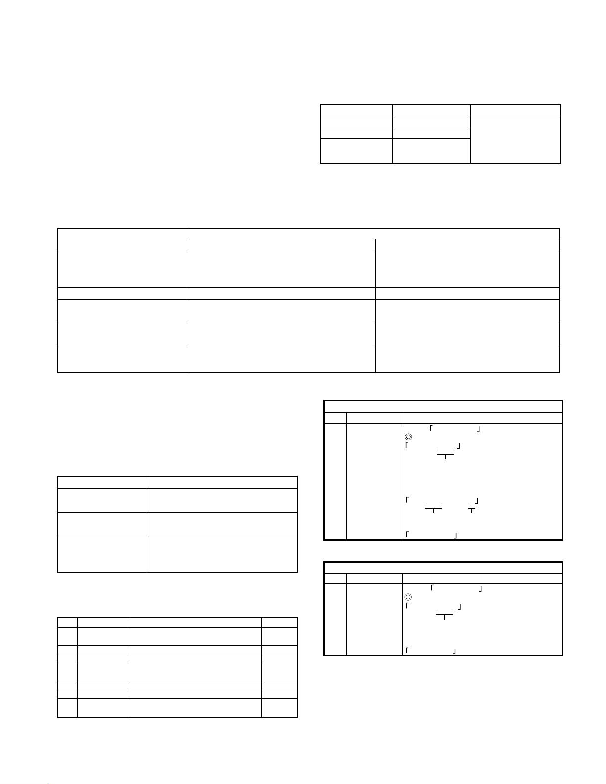
3-4 Key Operations for Adjustment
(1) Setting of Continuous Playback Mode
No. Key Display/Function
1VOLUME Select CREC-PLAY
2Load a recordable disc.
3(MD)6
(MD)6
CREC (ZZZZ) (CREC address)
0300h cluster = recording start point
ó
CPLAY ?
4CPLAY MID
C = XXXX a = YY (error)
C1 error ADIP error
address MID = 0300h cluster
5STOP CREC-PLAY
ó
(1) Setting of Continuous Recording Mode
No. Key Display/Function
1VOLUME Select CREC-PLAY
2Load a recordable disc.
3(MD) CREC (ZZZZ) (CREC address)
0300h cluster = recording start point
CPLAY ?
4STOP CREC-PLAY
6
4. Electrical adjustment
4-1 Precaution during confirmation of Laser Diode
emission
During adjustment, do not view the emission of a laser
diode from just above for confirmation. This may dam-
age your eyes.
3-6 Continuous Playbac Mode
3-7 Continuous Recording Mode
No. LCD DESCRIPTION SECTION
1 TEMP ADJU The work of adjustment is unnecessary
in this mode. 4-5
2 LDPWR ADJU Laser power adjustment. 4-6
3 LDPWR CHEC Laser power check. 4-6
4 EFBAL ADJU EF balance adjustment
(Traverse adjustment). 4-7
5 TE B. ADJ Automatic EF balance adjustment. 4-8
6 FBIAS ADJU Focus bias adjustment. 4-9
7 CREC-PLAY Continuous recording mode. 3-7
Continuous playback mode. 3-6
3-5 Selection of Adjustment Test Mode
• Whenever the [volume/multi-control] knob is turned the
adjustment test mode is selected.
For more information on each adjustment mode, refer to
each section of 4, "Electrical adjustment".