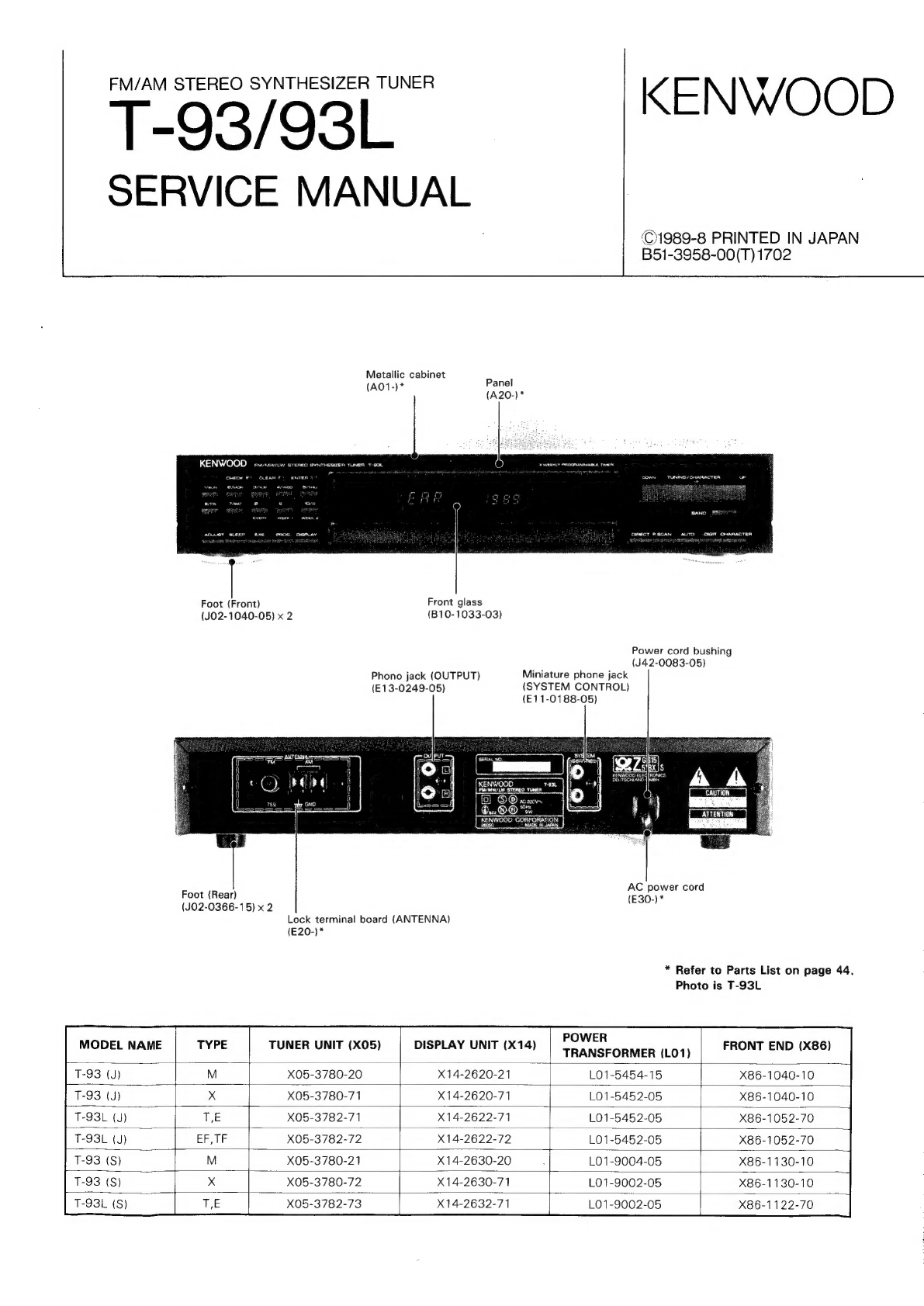
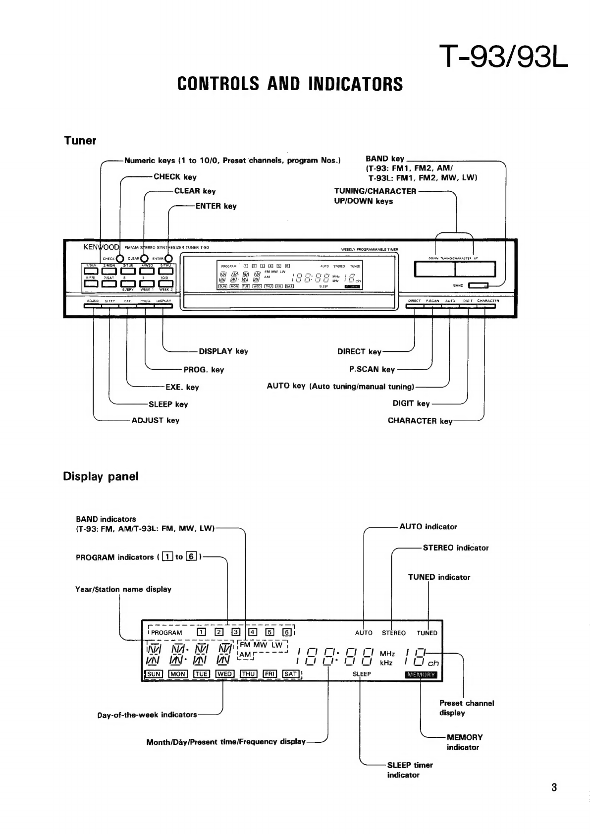
Kenwood T-93 User manual
Other Kenwood Tuner manuals

Kenwood
Kenwood KTC-WB100 User manual

Kenwood
Kenwood KTC-SR901 - Digital Satellite Tuner User manual

Kenwood
Kenwood KT-3050 User manual

Kenwood
Kenwood KTC-HR200 - HD Radio Tuner Box User manual

Kenwood
Kenwood KT-660 User manual

Kenwood
Kenwood KT-990D User manual

Kenwood
Kenwood AT-300 User manual

Kenwood
Kenwood Z-838W User manual

Kenwood
Kenwood KRC-929 User manual

Kenwood
Kenwood KTF-2010 User manual

Kenwood
Kenwood T-91 User manual

Kenwood
Kenwood AT-120 User manual

Kenwood
Kenwood KT-2010 User manual

Kenwood
Kenwood KTC-SR902 - Sirius Satellite Radio Tuner User manual

Kenwood
Kenwood KT-7500 User manual

Kenwood
Kenwood KTC-HR300 - HD Radio Tuner Box User manual

Kenwood
Kenwood AT-200 User manual

Kenwood
Kenwood KTF-2010 User manual

Kenwood
Kenwood AT-130 User manual

Kenwood
Kenwood KT-57 User manual


Popular Tuner manuals by other brands


MFJ
MFJ MFJ-928 instruction manual

NAD
NAD C 445 owner's manual

Sony
Sony ST-SA5ES operating instructions

Sirius Satellite Radio
Sirius Satellite Radio SC-FM1 user guide

Antique Automobile Radio
Antique Automobile Radio 283501B Installation and operating instructions

Monacor
Monacor PA-1200R instruction manual