Kenworth T300 User manual

T300
Body Builders’ Manual

Kenworth Truck Co. 6/99 I
BODY BUILDERS’ MANUAL
CONTENTS
SECTION 1 INTRODUCTION
SCOPE . . . . . . . . . . . . . . . . . . . . . . . . . . . . . . . . . . . . . . . . . . . . . . . . 1-1
SECTION 2 SAFETY AND COMPLIANCE
SAFETY SIGNALS . . . . . . . . . . . . . . . . . . . . . . . . . . . . . . . . . . . . . . . 2-1
Warnings, cautions, and notes . . . . . . . . . . . . . . . . . . . . . . . . . . . . 2-1
FEDERAL MOTOR VEHICLE SAFETY STANDARDS (FMVSS) COMPLIANCE 2-1
Incomplete Vehicle Certification . . . . . . . . . . . . . . . . . . . . . . . . . . . 2-2
SECTION 3 DIMENSIONS
ABBREVIATIONS . . . . . . . . . . . . . . . . . . . . . . . . . . . . . . . . . . . . . . . . 3-1
TURNING RADIUS . . . . . . . . . . . . . . . . . . . . . . . . . . . . . . . . . . . . . . . 3-1
OVERALL DIMENSIONS. . . . . . . . . . . . . . . . . . . . . . . . . . . . . . . . . . . 3-1
Side View — T300 with Single Rear Axle . . . . . . . . . . . . . . . . . . . . 3-2
Side View — T300 with Tandem Rear Axle . . . . . . . . . . . . . . . . . . 3-3
Front and Rear Views — T300 . . . . . . . . . . . . . . . . . . . . . . . . . . . . 3-4
DETAIL VIEWS . . . . . . . . . . . . . . . . . . . . . . . . . . . . . . . . . . . . . . . . . . 3-5
Side View Detail — T300 . . . . . . . . . . . . . . . . . . . . . . . . . . . . . . . . 3-5
Left Side: Step and Cab Floor Height — T300 . . . . . . . . . . . . . . . . 3-6
Right Side: Step and Cab Floor Height — T300 . . . . . . . . . . . . . . . 3-7
Crossmember Locations — T300 . . . . . . . . . . . . . . . . . . . . . . . . . . 3-8
Fuel Tank Locations — T300 . . . . . . . . . . . . . . . . . . . . . . . . . . . . . 3-9
COMPONENTS. . . . . . . . . . . . . . . . . . . . . . . . . . . . . . . . . . . . . . . . . 3-10
Frame Rail Configurations — T300 . . . . . . . . . . . . . . . . . . . . . . . 3-10
Battery Box and Air Tanks — T300 . . . . . . . . . . . . . . . . . . . . . . . 3-10
Fuel Tank and Exhaust — T300 . . . . . . . . . . . . . . . . . . . . . . . . . . 3-11
22-inch Fuel Tanks — T300 . . . . . . . . . . . . . . . . . . . . . . . . . . . . . 3-11
Horizontal Muffler-Vertical Tailpipe on Cab — T300 . . . . . . . . . . . 3-12
SECTION 4 BODY MOUNTING
CRITICAL CLEARANCES. . . . . . . . . . . . . . . . . . . . . . . . . . . . . . . . . . 4-1
Rear Wheels and Cab . . . . . . . . . . . . . . . . . . . . . . . . . . . . . . . . . . 4-1
Chassis with Outserts . . . . . . . . . . . . . . . . . . . . . . . . . . . . . . . . . . . 4-2
BODY MOUNTING USING BRACKETS . . . . . . . . . . . . . . . . . . . . . . . 4-2
Frame Sill . . . . . . . . . . . . . . . . . . . . . . . . . . . . . . . . . . . . . . . . . . . . 4-2
Brackets . . . . . . . . . . . . . . . . . . . . . . . . . . . . . . . . . . . . . . . . . . . . . 4-3
Mounting Holes . . . . . . . . . . . . . . . . . . . . . . . . . . . . . . . . . . . . . . . . 4-3
Frame Drilling . . . . . . . . . . . . . . . . . . . . . . . . . . . . . . . . . . . . . . . . . 4-4

Kenworth Truck Co. 6/99 II
CONTENTS
BODY MOUNTING USING U–BOLTS. . . . . . . . . . . . . . . . . . . . . . . . . 4-4
Spacers . . . . . . . . . . . . . . . . . . . . . . . . . . . . . . . . . . . . . . . . . . . . . 4-4
Rear Body Mount . . . . . . . . . . . . . . . . . . . . . . . . . . . . . . . . . . . . . . 4-5
SECTION 5 FRAME MODIFICATIONS
INTRODUCTION . . . . . . . . . . . . . . . . . . . . . . . . . . . . . . . . . . . . . . . . . 5-1
DRILLING RAILS. . . . . . . . . . . . . . . . . . . . . . . . . . . . . . . . . . . . . . . . . 5-1
Location and Hole Pattern . . . . . . . . . . . . . . . . . . . . . . . . . . . . . . . 5-1
MODIFYING FRAME LENGTH . . . . . . . . . . . . . . . . . . . . . . . . . . . . . . 5-1
Frame Insert . . . . . . . . . . . . . . . . . . . . . . . . . . . . . . . . . . . . . . . . . . 5-1
Changing Wheelbase . . . . . . . . . . . . . . . . . . . . . . . . . . . . . . . . . . . 5-2
Crossmembers . . . . . . . . . . . . . . . . . . . . . . . . . . . . . . . . . . . . . . . . 5-4
WELDING . . . . . . . . . . . . . . . . . . . . . . . . . . . . . . . . . . . . . . . . . . . . . . 5-4
Precautions . . . . . . . . . . . . . . . . . . . . . . . . . . . . . . . . . . . . . . . . . . . 5-4
SECTION 6 ELECTRICAL
INTRODUCTION . . . . . . . . . . . . . . . . . . . . . . . . . . . . . . . . . . . . . . . . . 6-1
ELECTRICAL CIRCUITS. . . . . . . . . . . . . . . . . . . . . . . . . . . . . . . . . . . 6-1
Capacity . . . . . . . . . . . . . . . . . . . . . . . . . . . . . . . . . . . . . . . . . . . . . 6-1
Prewired Body Harness . . . . . . . . . . . . . . . . . . . . . . . . . . . . . . . . . 6-1
Fuse and Circuit Identification . . . . . . . . . . . . . . . . . . . . . . . . . . . . 6-2
Circuits Wired Through the Ignition . . . . . . . . . . . . . . . . . . . . . . . . 6-4
Circuits Wired to Battery . . . . . . . . . . . . . . . . . . . . . . . . . . . . . . . . . 6-4
INSTALLING A THIRD BATTERY . . . . . . . . . . . . . . . . . . . . . . . . . . . . 6-5
WIRING FOR A LIFTGATE . . . . . . . . . . . . . . . . . . . . . . . . . . . . . . . . . 6-5
Liftgate Power Source . . . . . . . . . . . . . . . . . . . . . . . . . . . . . . . . . . . 6-5
Connecting the Liftgate Power . . . . . . . . . . . . . . . . . . . . . . . . . . . . 6-6
APPENDIX A VEHICLE IDENTIFICATION
VEHICLE IDENTIFICATION NUMBER . . . . . . . . . . . . . . . . . . . . . . . . A-1
VIN Location . . . . . . . . . . . . . . . . . . . . . . . . . . . . . . . . . . . . . . . . . . A-1
Chassis Number Locations . . . . . . . . . . . . . . . . . . . . . . . . . . . . . . . A-1
CERTIFICATION LABELS . . . . . . . . . . . . . . . . . . . . . . . . . . . . . . . . . . A-1
Components and Weights Label . . . . . . . . . . . . . . . . . . . . . . . . . . . A-1
Tire/Rim and Weight Rating Data Label . . . . . . . . . . . . . . . . . . . . . A-2
Incomplete Vehicle Certification Label . . . . . . . . . . . . . . . . . . . . . . A-2
Noise Emission Label . . . . . . . . . . . . . . . . . . . . . . . . . . . . . . . . . . . A-2
Paint Identification Label . . . . . . . . . . . . . . . . . . . . . . . . . . . . . . . . . A-2
COMPONENT IDENTIFICATION . . . . . . . . . . . . . . . . . . . . . . . . . . . . A-2
Engine Identification . . . . . . . . . . . . . . . . . . . . . . . . . . . . . . . . . . . . A-2
Transmission Identification . . . . . . . . . . . . . . . . . . . . . . . . . . . . . . . A-2
Front Axle Identification . . . . . . . . . . . . . . . . . . . . . . . . . . . . . . . . . A-2
Rear Axle Identification . . . . . . . . . . . . . . . . . . . . . . . . . . . . . . . . . . A-3

Kenworth Truck Co. 6/99 III
CONTENTS
APPENDIX B WEIGHT DISTRIBUTION
INTRODUCTION . . . . . . . . . . . . . . . . . . . . . . . . . . . . . . . . . . . . . . . . . B-1
Abbreviations . . . . . . . . . . . . . . . . . . . . . . . . . . . . . . . . . . . . . . . . . B-1
CALCULATIONS . . . . . . . . . . . . . . . . . . . . . . . . . . . . . . . . . . . . . . . . . B-2
Weight Distribution without Body . . . . . . . . . . . . . . . . . . . . . . . . . . B-2
Weight Distribution with Body . . . . . . . . . . . . . . . . . . . . . . . . . . . . . B-3
COMPLETE (LOADED) VEHICLE. . . . . . . . . . . . . . . . . . . . . . . . . . . . B-7
Water Level Load . . . . . . . . . . . . . . . . . . . . . . . . . . . . . . . . . . . . . . B-7
Body Length . . . . . . . . . . . . . . . . . . . . . . . . . . . . . . . . . . . . . . . . . . B-8
INDEX

Kenworth Truck Co. 6/99 IV
CONTENTS
FIGURES
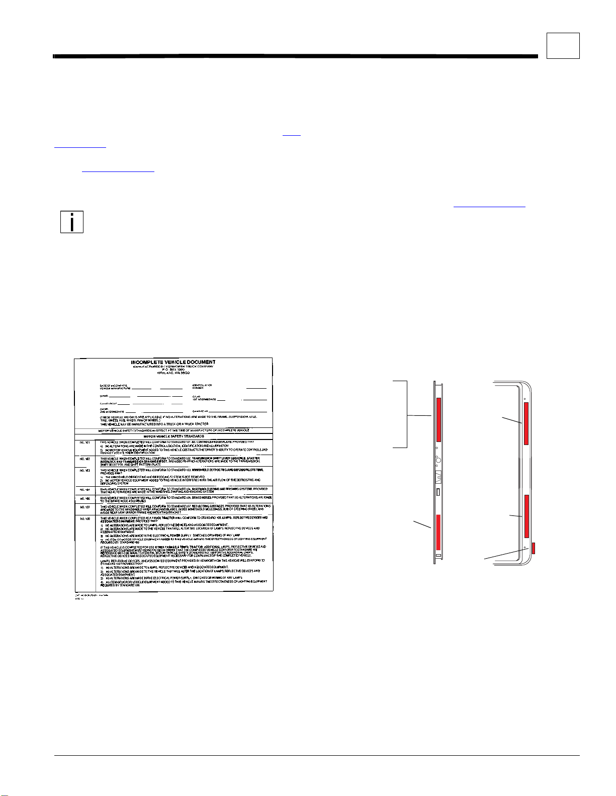
Figure 2–1. Incomplete Vehicle Certification Document. . . . . . . . . . . . . . . . . . . . . . . . . . . . . . . . . . . . . . . . . . . . .2-2
Figure 2–2. Location of Certification Labels - Driver’s Door . . . . . . . . . . . . . . . . . . . . . . . . . . . . . . . . . . . . . . . . . .2-2
Figure 3–1. T300 W/ Single Rear Axle: Height and Length Measurements. . . . . . . . . . . . . . . . . . . . . . . . . . . . . . 3-2
Figure 3–2. T300 W/ Tandem Rear Axle: Height and Length Measurements. . . . . . . . . . . . . . . . . . . . . . . . . . . . .3-3
Figure 3–3. T300 Front View: Width and Ground Clearance Measurements [inches (mm)]. . . . . . . . . . . . . . . . . .3-4
Figure 3–4. T300 Rear View: Width and Ground Clearance Measurements [inches (mm)]. . . . . . . . . . . . . . . . . .3-4
Figure 3–5. T300 Detailed Side View: Specific Measurements [inches (mm)]. . . . . . . . . . . . . . . . . . . . . . . . . . . . 3-5
Figure 3–6. T300 Battery Box Step and Cab Floor: side view, left side. . . . . . . . . . . . . . . . . . . . . . . . . . . . . . . . .3-6
Figure 3–7. T300 Fuel Tank Step and Cab Floor: side view, right side. . . . . . . . . . . . . . . . . . . . . . . . . . . . . . . . . .3-7
Figure 3–8. T300 Crossmember Location and Overall Width with Doors Open. . . . . . . . . . . . . . . . . . . . . . . . . . .3-8
Figure 3–9. T300 Fuel Tank Locations. . . . . . . . . . . . . . . . . . . . . . . . . . . . . . . . . . . . . . . . . . . . . . . . . . . . . . . . . .3-9
Figure 3–10. T300 10.5 and 10.62–Inch Rail Measurements [Inches (mm)] and Strength Characteristics. . . . . .3-10
Figure 3–11. T300 Battery Box and Air Tank Measurements [Inches (mm)]. . . . . . . . . . . . . . . . . . . . . . . . . . . . .3-10
Figure 3–12. T300 Standard Fuel Tank and Exhaust Measurements [Inches (mm)]. . . . . . . . . . . . . . . . . . . . . . .3-11
Figure 3–13. T300 Optional 22-inch Fuel Tank Mounting Measurements [Inches (mm)]. . . . . . . . . . . . . . . . . . . .3-11
Figure 3–14. T300 Vertical Tailpipe on Side of Cab [Inches (mm)]. . . . . . . . . . . . . . . . . . . . . . . . . . . . . . . . . . . . .3-12
Figure 3–15. T300 Vertical Tailpipe on Back of Cab [Inches (mm)]. . . . . . . . . . . . . . . . . . . . . . . . . . . . . . . . . . . .3-12
Figure 4–1. Minimum Clearance Between Top of Rear Tires and Body Structure Overhang. . . . . . . . . . . . . . . . .4-1
Figure 4–2. Minimum Back–of–Cab Clearance. . . . . . . . . . . . . . . . . . . . . . . . . . . . . . . . . . . . . . . . . . . . . . . . . . . .4-1
Figure 4–3. Air Gap with Frame Rail with Outsert . . . . . . . . . . . . . . . . . . . . . . . . . . . . . . . . . . . . . . . . . . . . . . . . .4-2
Figure 4–4. Spacer Between Frame Sill and Body Rail — Rubber or Plastic. . . . . . . . . . . . . . . . . . . . . . . . . . . . . 4-3
Figure 4–5. High Compression Spring Between the Mounting Bolt and Upper Bracket. . . . . . . . . . . . . . . . . . . . .4-3
Figure 4–6. Rubber Spacer Between Brackets. . . . . . . . . . . . . . . . . . . . . . . . . . . . . . . . . . . . . . . . . . . . . . . . . . . .4-3
Figure 4–7. Hole Location Guidelines for Frame Rail and Bracket. . . . . . . . . . . . . . . . . . . . . . . . . . . . . . . . . . . . .4-3
Figure 4–8. Crossmember–Gusset Hole Pattern Requirements. . . . . . . . . . . . . . . . . . . . . . . . . . . . . . . . . . . . . . .4-4
Figure 4–9. Acceptable U–Bolt Mounting with Wood and Fabricated Spacers. . . . . . . . . . . . . . . . . . . . . . . . . . . .4-5
Figure 4–10. Clearance Space for Air Lines and Cables. . . . . . . . . . . . . . . . . . . . . . . . . . . . . . . . . . . . . . . . . . . . .4-5
Figure 4–11. Example of Fishplate Bracket at Rear End of Body, used with U–Bolts. . . . . . . . . . . . . . . . . . . . . . .4-5
Figure 5–1. Detail of Frame Extensions and Joint Welding. . . . . . . . . . . . . . . . . . . . . . . . . . . . . . . . . . . . . . . . . . .5-2
Figure 5–2. Frame Insert . . . . . . . . . . . . . . . . . . . . . . . . . . . . . . . . . . . . . . . . . . . . . . . . . . . . . . . . . . . . . . . . . . . .5-2
Figure 5–3. Comparison of Original, Shortened, and Extended Wheelbases. . . . . . . . . . . . . . . . . . . . . . . . . . . . .5-3
Figure 5–4. Crossmember Added When Distance Exceeds 60 Inches (1524mm). . . . . . . . . . . . . . . . . . . . . . . . .5-4
Figure 6–1. Location of Prewired Body Harness Connection. . . . . . . . . . . . . . . . . . . . . . . . . . . . . . . . . . . . . . . . .6-1
Figure 6–2. Prewired Truck and Body Harness (before 4/98) . . . . . . . . . . . . . . . . . . . . . . . . . . . . . . . . . . . . . . . .6-2
Figure 6–3. Prewired Truck and Body Harness (after 3/98) . . . . . . . . . . . . . . . . . . . . . . . . . . . . . . . . . . . . . . . . . .6-3
Figure 6–4. Adding a Third Battery . . . . . . . . . . . . . . . . . . . . . . . . . . . . . . . . . . . . . . . . . . . . . . . . . . . . . . . . . . . . .6-5
Figure 6–5. Liftgate Circuit Breaker Inside Battery Box. . . . . . . . . . . . . . . . . . . . . . . . . . . . . . . . . . . . . . . . . . . . . .6-6
Figure A–1. Vehicle Identification Number (VIN). . . . . . . . . . . . . . . . . . . . . . . . . . . . . . . . . . . . . . . . . . . . . . . . . . .A-1
Figure A–2. Driver’s Door and Door Frame Labels . . . . . . . . . . . . . . . . . . . . . . . . . . . . . . . . . . . . . . . . . . . . . . . . .A-1
Figure A–3. Cummins Identification Plate. . . . . . . . . . . . . . . . . . . . . . . . . . . . . . . . . . . . . . . . . . . . . . . . . . . . . . . .A-2
Figure A–4. Front Axle Identification. . . . . . . . . . . . . . . . . . . . . . . . . . . . . . . . . . . . . . . . . . . . . . . . . . . . . . . . . . . .A-2
Figure A–5. Rear Axle Identification Labels. . . . . . . . . . . . . . . . . . . . . . . . . . . . . . . . . . . . . . . . . . . . . . . . . . . . . . .A-3
Figure B–1. Balanced Load: CGf 100 in. from front axle. . . . . . . . . . . . . . . . . . . . . . . . . . . . . . . . . . . . . . . . . . . . .B-2
Figure B–2. Unbalanced Load: CGf 133 in. from front axle. . . . . . . . . . . . . . . . . . . . . . . . . . . . . . . . . . . . . . . . . . .B-2
Figure B–3. Balanced Body Unloaded: CGf 156 in. (3962 mm) from front axle. . . . . . . . . . . . . . . . . . . . . . . . . . .B-5
Figure B–4. Liftgate Example: CGf 246 in. (6248 mm) from front axle. . . . . . . . . . . . . . . . . . . . . . . . . . . . . . . . . .B-6
Figure B–5. Loaded Vehicle Example: CGf 156 in. (3962 mm) from front axle. . . . . . . . . . . . . . . . . . . . . . . . . . . .B-7

Kenworth Truck Co. 6/99 V
CONTENTS
TABLES
TABLE 3-1. Abbreviations Used. . . . . . . . . . . . . . . . . . . . . . . . . . . . . . . . . . . . . . . . . . . . . . . . . . . . . . . . . . . . . . . . . . .3-1
TABLE 3-2. Turning Radius-T300 w/single rear axle . . . . . . . . . . . . . . . . . . . . . . . . . . . . . . . . . . . . . . . . . . . . . . . . . . .3-1
TABLE 3-3. Turning Radius-T300 w/tandem rear axles . . . . . . . . . . . . . . . . . . . . . . . . . . . . . . . . . . . . . . . . . . . . . . . . .3-1
TABLE 3-4. T300 w/ Single Rear Axle: Overall Dimensions [inches (mm)]. . . . . . . . . . . . . . . . . . . . . . . . . . . . . . . . . . .3-2
TABLE 3-5. T300 w/ Tandem Rear Axle: Overall Dimensions [inches (mm)]. . . . . . . . . . . . . . . . . . . . . . . . . . . . . . . . .3-3
TABLE 3-6. T300 Front and Rear Suspension (FS/RS) Centerline (C/L) to Rail Measurements. . . . . . . . . . . . . . . . . .3-5
TABLE 3-7. T300 Battery Box Step and Cab Floor Measurements. . . . . . . . . . . . . . . . . . . . . . . . . . . . . . . . . . . . . . . .3-6
TABLE 3-8. T300 Fuel Tank Step and Cab Floor Measurements. . . . . . . . . . . . . . . . . . . . . . . . . . . . . . . . . . . . . . . . . .3-7
TABLE 3-9. T300 Crossmember Locations: measured from front axle centerline [inches (mm)]. . . . . . . . . . . . . . . . . .3-8
TABLE 3-10.T300 Fuel Tank Locations for Standard Wheelbase Configurations [inches (mm)]. . . . . . . . . . . . . . . . . . .3-9
TABLE 6-1. Third Battery Installation Parts . . . . . . . . . . . . . . . . . . . . . . . . . . . . . . . . . . . . . . . . . . . . . . . . . . . . . . . . . .6-5
TABLE A-1. Model Year Letter (CODE) Designations. . . . . . . . . . . . . . . . . . . . . . . . . . . . . . . . . . . . . . . . . . . . . . . . . . .A-1
TABLE B-1. T300 Single Rear Axle “Bare” Chassis Tare Weights (no driver, no fuel), lb (kg). . . . . . . . . . . . . . . . . . . .B-3
TABLE B-2. T300 Tandem Rear Axle “Bare” Chassis Tare Weights (no driver, no fuel), lb (kg). . . . . . . . . . . . . . . . . . .B-4
TABLE B-3. T300 Options . . . . . . . . . . . . . . . . . . . . . . . . . . . . . . . . . . . . . . . . . . . . . . . . . . . . . . . . . . . . . . . . . . . . . . .B-4
TABLE B-4. T300 Weight distribution and chassis rating calculation (sample) . . . . . . . . . . . . . . . . . . . . . . . . . . . . . . .B-7
TABLE B-5. Recommended T300 Body Lengths (Single Rear Axle). . . . . . . . . . . . . . . . . . . . . . . . . . . . . . . . . . . . . . .B-8
TABLE B-6. Recommended T300 Body Lengths (Tandem Rear Axle). . . . . . . . . . . . . . . . . . . . . . . . . . . . . . . . . . . . . .B-8

1–1 6/99 Body Builders’ Manual
SECTION 1 INTRODUCTION
This manual was created to provide body builders with
appropriate information and guidelines useful in the
body planning and installation process. This information
will be helpful when installing bodies or other associ-
ated equipment.
This manual contains appropriate dimensional informa-
tion, guidelines for mounting bodies, guidelines for
modifying frames, electrical wiring information, and
other information useful in the body installation process.
The intended primary users of this manual are body
builders who install bodies and associated equipment
on Kenworth T300 Medium Duty vehicles. Dealers who
sell and service the vehicle will also find this information
useful.
This Body Builders’ Manual can be very useful when
specifying a vehicle, particularly when the body builder
is involved in the vehicle definition and ordering pro-
cess. Early in the process, professional body builders
can often contribute valuable information that reduces
the ultimate cost of the body installation.
This manual is not a maintenance manual or an
operation manual.
• For chassis maintenance and repair information
consult the
Kenworth Medium Duty Maintenance
Manual
available in the Service Department of the
selling dealer or you can order your own copy of the
maintenance manual from your local dealer.
• For chassis operating information consult the
Oper-
ator’s Manual
, included with each vehicle. They can
also be ordered from your local dealer.
SCOPE

Kenworth Truck Co. 6/99 2–1
SECTION 2 SAFETY AND COMPLIANCE
SAFETY SIGNALS
We’ve put a number of alerting messages in this book.
Please read and follow them. They are there for your
protection and information. These alerting messages
can help you avoid injury to yourself or others and help
prevent costly damage to the vehicle.
Key symbols and “signal words” are used to indicate
what kind of message is going to follow. Pay special
attention to comments prefaced by “WARNING”, “CAU-
TION”, and “NOTE.” Please don't ignore any of these
alerts.
Warnings, cautions, and notes
WARNING
When you see this word and symbol, the mes-
sage that follows is especially vital. It signals a
potentially hazardous situation which, if not
avoided, could result in death or serious injury.
This message will tell you what the hazard is,
what can happen if you don’t heed the warning,
and how to avoid it.
Example:
WARNING! Be sure to use a circuit breaker
designed to meet liftgate amperage require-
ments. An incorrectly specified circuit
breaker could result in a electrical overload
or fire situation. Follow the liftgate installa-
tion instructions and use a circuit breaker
with the recommeded capacity.
CAUTION
Signals a potentially hazardous situation
which, if not avoided, could result in minor or mod-
erate injury or damage to the vehicle.
Example:
CAUTION:
Never use a torch to make a hole
in the rail. Use the appropriate drill bit.
NOTE
Provides general information: for example, the
note could warn you on how to avoid damaging
your vehicle or how to drive the vehicle more effi-
ciently.
Example:
NOTE:
Be sure to provide maintenance access
to the battery box and fuel tank fill neck.
FEDERAL MOTOR VEHICLE SAFETY
STANDARDS (FMVSS) COMPLIANCE
As an Original Equipment Manufacturer (OEM), Ken-
worth Truck Co. ensures that our products comply with
all applicable Federal Motor Vehicle Safety Standards
(FMVSS). However, the fact that this vehicle has no
fifth–wheel and that a Body Builder (Final Stage Manu-
facturer) will be doing additional modifications means
that the vehicle was incomplete when it left the build
plant. See page 2–2 and Appendix A for additional
information.
Please take the time to read these mes-
sages when you see them, and remember:
WARNING
Indicates a potentially hazardous situation
which, if not avoided, could result in death or
serious injury.
CAUTION
Signals a potentially hazardous situation which,
if not avoided, could result in minor or moderate
injury or damage to the vehicle.
NOTE
Useful information that is related to the topic
being discussed.

Kenworth Truck Co. 6/99 2–2
SAFETY AND COMPLIANCE 2
Incomplete Vehicle Certification
An Incomplete Vehicle Document is shipped with the
vehicle, certifying that the vehicle is not complete. See
Figure 2–1. In addition, affixed to the driver's side door
frame or edge is an Incomplete Vehicle Certification
label. See Figure 2–2.. For further information on Vehi-
cle Certification and Identification, see APPENDIX A
“VEHICLE IDENTIFICATION.”
NOTE: These documents list the FMVSS reg-
ulations that the vehicle complied with when it
left the build plant. You should be aware that if
you modify or alter any of the components or
systems covered by these FMVSS regula-
tions, it is your responsibility as the Final
Stage Manufacturer to ensure that the com-
plete vehicle maintains compliance with the
particular FMVSS regulations when you com-
plete your modifications.
As the Final Stage Manufacturer, you should retain the
Incomplete Vehicle Document for your records. In addi-
tion, you should record and retain the manufacturer and
serial number of the tires on the vehicle. Upon comple-
tion of the vehicle (installation of the body and any other
modifications), you should affix your certification label
to the vehicle as required by Federal law. This tag iden-
tifies you as the “Final Stage Manufacturer” and certi-
fies that the vehicle complies with Federal Motor
Vehicle Safety Standards. (See Figure 2–2.)
Figure 2–1. Incomplete Vehicle Certification
Document.
01476
02378
DOOR FRAME
AND WEIGHT LABEL
(TRACTOR)
OR INCOMPLETE
VEHICLE
CERTIFICATION
LABEL (TRUCK)
TIRE, RIM,
AND WEIGHT
RATING DATA
LABEL
(TRUCK)
COMPONENTS
AND WEIGHTS
LABEL (TRUCK
CHASSIS
NUMBER
(STAMPED)
DOOR EDGE
TIRE,RIM,CERTIFICATION
MAJOR
OR TRACTOR)
FINAL STAGE MAN-
UFACTURERLABEL
(TO BE INSTALLED
BY FINAL STAGE
MANUFACTURER
(TRUCK ONLY)
Figure 2–2. Location of Certification
Labels - Driver’s Door

Kenworth Truck Co. 3–1
SECTION 3 DIMENSIONS
ABBREVIATIONS
Throughout this section and in other sections as well,
abbreviations are used to describe certain characteris-
tics on your vehicle. The chart below lists the abbrevi-
ated terms used.
TURNING RADIUS
Approximate turning radius specifications for the T300
are listed (by wheelbase) in the following tables. Tables
3-2 and 3-3 list turn radius information for chassis with
standard components. Optional components may give
different results.
OVERALL DIMENSIONS
This section includes drawings and charts of the stan-
dard T300 vehicle, including a 10,000 lb. front suspen-
sion, a 20,000 lb. rear suspension, and R250F
295/75R22.5 tires. Use these drawings to plan overall
vehicle configurations.
On the pages that follow, detail drawings show particu-
lar views of each vehicle component. They illustrate
important measurements critical to designing bodies of
all types. See the “Contents” at the beginning of the
manual to locate the drawing you need.
TABLE 3-1. Abbreviations Used.
A OVERALL VEHICLE LENGTH
AF FRAME RAIL OVERHANG LENGTH
BEHIND REAR AXLE
BFRONT BUMPER TO FRONT AXLE
LENGTH
CA BACK OF CAB TO REAR AXLE LENGTH
D CAB HEIGHT
WB WHEELBASE LENGTH
TABLE 3-2. Turning Radius-T300 w/single rear axle
T300 W/SINGLE REAR AXLE
WHEELBASE
(IN.) CURB TO
CURB (FT.) WALL TOWALL
(FT.)
145 20 23
150 21 24
160 22 25
185 25 28
200 27 30
215 29 32
230 31 34
245 32 35
260 34 37
280 36 39
TABLE 3-3. Turning Radius-T300 w/tandem rear
axles
T300 W/TANDEM REAR AXLES
WHEELBASE
(IN.) CURB TO
CURB (FT.) WALLTO WALL
(FT.)
165 24 28
175 26 29
190 27 30
205 29 32
220 31 34
235 33 36
250 35 38
260 36 39

Kenworth Truck Co. 3–2
DIMENSIONS 3
OVERALL DIMENSIONS — T300
Side View — T300 with Single Rear Axle
TABLE 3-4. T300 w/ Single Rear Axle: Overall Dimensions [inches (mm)].
WB A AF B CA * UNLADEN
D **
145 (3683) 237.2 (6025) 55 (1397)
37.2 (945)
77 (1956)
104.9 (2664)
150 (3810) 237.2 (6025) 50 (1270) 82 (2083)
160 (4064) 261.2 (6634) 64 (1626) 92 (2337)
185 (4699) 285.2 (7244) 63 (1600) 117 (2972)
200 (5080) 309.2 (7854) 72 (1829) 132 (3353)
215 (5461) 333.2 (8463) 81 (2057) 147 (3734)
230 (5842) 357.2 (9073) 90 (2286) 162 (4115)
245 (6223) 381.2 (9682) 99 (2515) 177 (4496)
260 (6604) 405.2 (10292) 108 (2743) 192 (4877)
280 (7112) 429.2 (10902) 112 (2845) 212 (5385)
* CA measured from true back of cab to rear axle centerline
** Determined with Front Tire Bridgestone R250F 295/75R22.5
Figure 3–1. T300 W/ Single Rear Axle: Height and Length Measurements.
03008
D
WB
A
CA
AF
B

Kenworth Truck Co. 3–3
DIMENSIONS 3
OVERALL DIMENSIONS — T300
Side View — T300 with Tandem Rear Axle
TABLE 3-5. T300 w/ Tandem Rear Axle: Overall Dimensions [inches (mm)].
WB A AF B CA * D **
175 (4445) 283.2 (7193) 71 (1803)
37.2 (945)
107 (2718)
104.9 (2664)
190 (4826) 307.2 (7803) 80 (2032) 122 (3099)
205 (5207) 331.2 (8412) 89 (2261) 137 (3480)
220 (5588) 355.2 (9022) 98 (2489) 152 (3861)
235 (5969) 379.2 (9632) 107 (2718) 167 (4242)
250 (6350) 403.2 (10241) 116 (2946) 182 (4623)
260 (6604) 427.2 (10851) 130 (3302) 192 (4877)
* CA measured from true back of cab to rear axle centerline
** Determined with Front Tire Bridgestone R250F 295/75R22.5
Figure 3–2. T300 W/ Tandem Rear Axle: Height and Length Measurements.
03008T
D
WB
A
CA
AF
B

Kenworth Truck Co. 3–4
DIMENSIONS 3
OVERALL DIMENSIONS — T300
Front and Rear Views — T300
02389
Figure 3–3. T300 Front View: Width and Ground Clearance Measurements [inches (mm)].
107.7
(2735)
8.9
(226) 79.1
(2019)
95.3
(2421)
Figure 3–4. T300 Rear View: Width and Ground Clearance Measurements [inches (mm)].
03005A
BOTTOM
FRAME
FLANGE
71.8
(1824)
36
(914)
17 (432)
46.3 (1177)
9.7
(248)
71.9 (1827)
96 (2440)
34
(864)

Kenworth Truck Co. 3–5
DIMENSIONS 3
OVERALL DIMENSIONS — T300
DETAIL VIEWS
Side View Detail — T300
TABLE 3-6. T300 Front and Rear Suspension (FS/RS) Centerline (C/L) to Rail Measurements.
LOAD REAR SUSPENSION
CENTERLINE OF AXLE TO BOTTOM
FLANGE OF RAIL [IN. (MM)]
FS RS
UNLADEN REYCO 79KB 8.4 (213) 9.0 (229)
LADEN 6.6 (168) 6.6 (168)
UNLADEN HENDRICKSON
HAS 210L/230L
8.4 (213) 7.8 (198)
LADEN 6.6 (168) 7.8 (198)
UNLADEN REYCO 102 8.4 (213) 8.5 (216)
LADEN 6.6 (168) 7.2 (183)
UNLADEN HENDRICKSON
HAS 402
8.4 (213) 7.8 (198)
LADEN 6.6 (168) 7.8 (198)
UNLADEN HENDRICKSON
RT2-400
8.4 (213) 8.6 (218)
LADEN 6.6 (168) 7.6 (193)
Figure 3–5. T300 Detailed Side View: Specific Measurements [inches (mm)].
03008
BOTTOM
FLANGE
AXLE C/L
FS RS
68
(1727)
76.7
(1948) 66.9
(1699)
82.8
(2102)
36
(914) 10.5
(267)
61
(1550)
37.2
(945)
30
(762)
29.8
(757)
SINGLE
REAR AXLE
TANDEM
REAR AXLE

Kenworth Truck Co. 3–6
DIMENSIONS 3
OVERALL DIMENSIONS — T300
Left Side: Step and Cab Floor Height — T300
TABLE 3-7. T300 Battery Box Step and Cab Floor Measurements.
POSITION UNLADEN
IN. (MM) LADEN
IN. (MM)
AFIRST
STEP 21.3 (540) 18.9 (481)
BSECOND
STEP 37.0 (940) 34.7 (881)
CCAB
FLOOR 44.6 (1133) 42 (1069)
Figure 3–6. T300 Battery Box Step and Cab Floor: side view, left side.
03012
A
BC

Kenworth Truck Co. 3–7
DIMENSIONS 3
OVERALL DIMENSIONS — T300
Right Side: Step and Cab Floor Height — T300
TABLE 3-8. T300 Fuel Tank Step and Cab Floor Measurements.
POSITION UNLADEN
IN. (MM) LADEN
IN. (MM)
AFIRST
STEP 23.3 (592) 21.0 (533)
BSECOND
STEP 38.1 (967) 35.8 (908)
CCAB
FLOOR 44.6 (1133) 42 (1069)
Figure 3–7. T300 Fuel Tank Step and Cab Floor: side view, right side.
9707211
A
B
C

Kenworth Truck Co. 3–8
DIMENSIONS 3
OVERALL DIMENSIONS — T300
Crossmember Locations — T300
TABLE 3-9. T300 Crossmember Locations: measured from front axle centerline [inches (mm)].
WHEELBASE A CB B CB C CB D E
145 90.7 (2305) — ➀————— —
146 - 150 79.7 (2025) ✓ ➀ ————— —
151 - 160 90.7 (2305) ✓————— —
161 - 185 101.7 (2585) ✓————— —
186 - 200 101.7 (2585) ✓140.3 (3565) ———— —
201 - 215 90.7 (2305) —118.3 (3005) ✓156.9 (3985) ——279.4 (7097)
216 - 230 101.7 (2585) ✓162.4 (4125) ✓———294.4 (7478)
231 - 245 101.7 (2585) ✓162.4 (4125) ✓———309.4 (7859)
246 - 260 101.7 (2585) ✓162.4 (4125) ✓201 (5105) ——324.4 (8240)
261 - 280 101.7 (2585) ✓140.3 (3565) —178.9 (4545) ✓217.5 (5525) 344.4 (8748)
TANDEM REAR AXLES
157 - 177 90.7 (2305) —————— —
178 - 193 90.7 (2305) ✓————— —
194 - 217 101.7 (2585) ✓————— —
218 - 231 101.7 (2585) ✓140.3 (3565) ———— —
232 - 247 90.7 (2305) —118.3 (3005) ✓156.9 (3985) ——325.4 (8265)
248 - 256 101.7 (2585) ✓151.4 (3845) ✓———340.4 (8646)
257 - 262 101.7 (2585) ✓156.9 (3985) ✓———350.4 (8900)
✓Driveline centerbearing (CB) mounted on this crossmember
➀Dimensions noted are based on the use of the standard T300 transmission, rear axle, and driveline.
03009
Figure 3–8. T300 Crossmember Location and Overall Width with Doors Open.
118
(2997)
50°–55°
A
B
C
DE

Kenworth Truck Co. 3–9
DIMENSIONS 3
OVERALL DIMENSIONS — T300
Fuel Tank Locations — T300
TABLE 3-10. T300 Fuel Tank Locations for Standard Wheelbase Configurations [inches (mm)].
FUEL TANK A * B
RH Under Cab
Rectangular Steel 50 Gal
32.8 (833)
33.5 (851)
Round 22” Aluminum
56 Gal 35.6 (904)
75 Gal 47.3 (1201)
100 Gal 62.2 (1580)
120 Gal 74.3 (1887)
LH Behind Cab
Rectangular Steel 50 Gal 78.3 (1989) 30.5 (775)
70 Gal 77.7 (1974) 42.6 (1082)
Round 22” Aluminum ** 56 Gal
77.3 (1963)
35.6 (904)
75 Gal 47.3 (1201)
100 Gal 62.2 (1580)
* Measured from centerline of front axle
** Also RH Behind Cab.
03011
Figure 3–9. T300 Fuel Tank Locations.
A
B
A B

Kenworth Truck Co. 3–10
DIMENSIONS 3
OVERALL DIMENSIONS — T300
COMPONENTS
Frame Rail Configurations — T300
Battery Box and Air Tanks — T300
YIELD: 80,000 psi
SECTION MODULUS:
16.75 cu in.
RBM: 1,340,000 lb. in.
10.5–INCH RAIL
01161-1
Figure 3–10. T300 10.5 and 10.62–Inch Rail Measurements
[Inches (mm)] and Strength Characteristics.
01162-1
YIELD: 110,000 psi
SECTION MODULUS:
14.8 cu in.
RBM: 1,628,000 lb. in.
10.62–INCH RAIL
HEAT TREATED
3.5
(88.9)
3.74
(95)
.5
(12.7)
.25
(6.35) .25
(6.35)
10
(254)
10.5
(266.7)
10.24
(260)
3.46
(87.8)
.31
(7.94)
10
(254) 10.62
(269.9)
Figure 3–11. T300 Battery Box and Air Tank Measurements
[Inches (mm)].
STANDARD BATTERY
BOX WITH AIR TANKS
03006-1
REAR VIEW
33
(838)
GROUND
13.6 (346) LADEN
15.9 (404) UNLADEN
12.6
(319)
7.2
(184)
8.7
(220)

Kenworth Truck Co. 3–11
DIMENSIONS 3
OVERALL DIMENSIONS — T300
Fuel Tank and Exhaust — T300
22-inch Fuel Tanks — T300
Figure 3–12. T300 Standard Fuel Tank and Exhaust
Measurements [Inches (mm)].
STANDARD FUEL TANK MOUNTING
03007
03006-2
REAR VIEW
EXHAUST / MUFFLER MOUNTING
HORIZONTAL
1.3
(32)
13.8
(351)
2.5
(63)
26.2
(665)
6.8
(172)
23
(583)
REAR VIEW
12.2
(309)
GROUND
13.2
(334) 13.0 (331) LADEN
15.3 (389) UNLADEN
FROM OUTSIDE
OF RAIL
FROM OUTSIDE
OF RAIL
1.8
(44)
Figure 3–13. T300 Optional 22-inch Fuel Tank Mounting Measurements [Inches (mm)].
RIGHT SIDE UNDER CABLEFT SIDE BEHIND CAB
REAR VIEW REAR VIEW
GROUND
9.9 (251) LADEN
12.2 (310) UNLADEN
25.9
(658)
11.0
(279)
16.3
(414)
Table of contents
Other Kenworth Truck manuals