Kenworth T440 2010 User manual

®
2010
Kenworth T440/T470
Body Builder Manual

2010 Emissions
Kenworth T440/T470
Body Builder Manual

T470/T440 Body Builder
Manual Contents
iv
12/09
SECTION 1: INTRODUCTION 1-1
SECTION 2: SAFETY AND COMPLIANCE 2-1
SAFETY SIGNALS . . . . . . . . . . . . . . . . . . . . . . . . . . . . . . . . . . . . . . 2-1
FEDERAL MOTOR VEHICLE SAFETYSTANDARDS COMPLIANCE . . . . . . . . . . . . 2-2
SECTION 3: DIMENSIONS 3-1
DIMENSIONS . . . . . . . . . . . . . . . . . . . . . . . . . . . . . . . . . . . . . . . . . 3-1
ABBREVIATIONS . . . . . . . . . . . . . . . . . . . . . . . . . . . . . . . . . . . . . . . 3-1
TURNING RADIUS . . . . . . . . . . . . . . . . . . . . . . . . . . . . . . . . . . . . . . 3-1
KENWORTH AXLE TRACK/TIRE WIDTH SUMMARY . . . . . . . . . . . . . . . . . . . . 3-4
OVERALL DIMENSIONS . . . . . . . . . . . . . . . . . . . . . . . . . . . . . . . . . . . 3-5
T470 FIXED GRILLE HOOD W/O EXTENDED FRONT FRAME . . . . . . . . . . . . . . . 3-6
T440 DAYCAB . . . . . . . . . . . . . . . . . . . . . . . . . . . . . . . . . . . . . . . . . 3-7
T470 FIXED GRILLE HOOD WITH EXTENDED FRONT FRAME . . . . . . . . . . . . . . 3-9
38” AEROCAB . . . . . . . . . . . . . . . . . . . . . . . . . . . . . . . . . . . . . . . . .3-10
RIDE HEIGHTS . . . . . . . . . . . . . . . . . . . . . . . . . . . . . . . . . . . . . . . .3-12
REAR SUSPENSION LAYOUTS . . . . . . . . . . . . . . . . . . . . . . . . . . . . . . .3-14
REYCO 79KB SINGLE REAR AXLE . . . . . . . . . . . . . . . . . . . . . . . . . . . . .3-14
REYCO 102 TANDEM REAR AXLE . . . . . . . . . . . . . . . . . . . . . . . . . . . . . .3-15
NEWAY AD 123 SINGLE REAR AXLE . . . . . . . . . . . . . . . . . . . . . . . . . . . .3-16
NEWAY AD 246 TANDEM SUSPENSION. . . . . . . . . . . . . . . . . . . . . . . . . . .3-17
HENDRICKSON PRIMAAX TANDEM SUSPENSION. . . . . . . . . . . . . . . . . . . . .3-18
HENDRICKSON HMX TANDEM SUSPENSION . . . . . . . . . . . . . . . . . . . . . . .3-19
HENDRICKSON RT TANDEM SUSPENSION. . . . . . . . . . . . . . . . . . . . . . . . .3-20
KENWORTH AG 380 TANDEM SUSPENSION . . . . . . . . . . . . . . . . . . . . . . . .3-22
KENWORTH AG 400/460 TANDEM SUSPENSION. . . . . . . . . . . . . . . . . . . . . .3-23
KENWORTH AG 400L TANDEM SUSPENSION . . . . . . . . . . . . . . . . . . . . . . .3-24
KENWORTH AG 460 TANDEM SUSPENSION . . . . . . . . . . . . . . . . . . . . . . . .3-25
CHALMERS 856-46 TANDEM SUSPENSION. . . . . . . . . . . . . . . . . . . . . . . . .3-26
PUSHER AXLES . . . . . . . . . . . . . . . . . . . . . . . . . . . . . . . . . . . . . . .3-27
PTO CLEARANCES . . . . . . . . . . . . . . . . . . . . . . . . . . . . . . . . . . . . . .3-32
SECTION 4: EXHAUST AND AFTERTREATMENT 4-1
EXHAUST AND AFTER-TREATMENT INFORMATION . . . . . . . . . . . . . . . . . . . . 4-1
GENERAL GUIDELINES FOR DEF SYSTEM . . . . . . . . . . . . . . . . . . . . . . . . 4-3
INSTALLATION REQUIREMENTS AND DIMENSIONS FOR DEF SYSTEM . . . . . . . . . 4-3
MEASUREMENT REFERENCE POINTS . . . . . . . . . . . . . . . . . . . . . . . . . . . 4-4
GENERAL EXHAUST INFORMATION . . . . . . . . . . . . . . . . . . . . . . . . . . . .4-10
EXHAUST INFORMATION . . . . . . . . . . . . . . . . . . . . . . . . . . . . . . . . . .4-19
SECTION 5: FRAME LAYOUTS 5-1
FRAME LAYOUTS. . . . . . . . . . . . . . . . . . . . . . . . . . . . . . . . . . . . . . . 5-1
COMMON OPTIONAL COMPONENTS. . . . . . . . . . . . . . . . . . . . . . . . . . . . 5-2
FRAME LAYOUT INDEX. . . . . . . . . . . . . . . . . . . . . . . . . . . . . . . . . . . . 5-4
CHARTS . . . . . . . . . . . . . . . . . . . . . . . . . . . . . . . . . . . . . . . . . . . . 5-5
SECTION 6: BODY MOUNTING 6-1
FRONT FRAME DIMENSIONS . . . . . . . . . . . . . . . . . . . . . . . . . . . . . . . . 6-1
FRAME INFORMATION . . . . . . . . . . . . . . . . . . . . . . . . . . . . . . . . . . . . 6-2
BODY MOUNTING USING BRACKETS. . . . . . . . . . . . . . . . . . . . . . . . . . . . 6-3
MOUNTING HOLES. . . . . . . . . . . . . . . . . . . . . . . . . . . . . . . . . . . . . . 6-5
BODY MOUNTING USING U–BOLTS. . . . . . . . . . . . . . . . . . . . . . . . . . . . . 6-6

T470/T440 Body Builder
Manual Contents
v12/09
SECTION 7: FRAME MODIFICATIONS 7-1
FRAME MODIFICATIONS. . . . . . . . . . . . . . . . . . . . . . . . . . . . . . . . . . . 7-1
MODIFYING FRAME LENGTH . . . . . . . . . . . . . . . . . . . . . . . . . . . . . . . . 7-2
CHANGING WHEELBASE . . . . . . . . . . . . . . . . . . . . . . . . . . . . . . . . . . 7-3
CROSSMEMBERS . . . . . . . . . . . . . . . . . . . . . . . . . . . . . . . . . . . . . . 7-5
WELDING . . . . . . . . . . . . . . . . . . . . . . . . . . . . . . . . . . . . . . . . . . . 7-6
TORQUE REQUIREMENTS. . . . . . . . . . . . . . . . . . . . . . . . . . . . . . . . . . 7-7
SECTION 8: ELECTRICAL 8-1
ELECTRICAL . . . . . . . . . . . . . . . . . . . . . . . . . . . . . . . . . . . . . . . . . 8-1
MULTIPLEX INSTRUMENTATION. . . . . . . . . . . . . . . . . . . . . . . . . . . . . . . 8-1
ACCESSING GAUGES AND SWITCHES. . . . . . . . . . . . . . . . . . . . . . . . . . . 8-9
TELLTALE SYMBOLS . . . . . . . . . . . . . . . . . . . . . . . . . . . . . . . . . . . . .8-17
SPARE RELAYS BODY BUILDER INSTALLED(FOR LOADS EXCEEDING 20 AMPS) . . .8-23
ADDITIONAL SPARE CIRCUITS . . . . . . . . . . . . . . . . . . . . . . . . . . . . . . .8-25
REMOTE PTO/THROTTLE HARNESS . . . . . . . . . . . . . . . . . . . . . . . . . . . .8-27
MULTIFUNCTION TURN SIGNAL STALK, CHASSIS NODE & CHASSIS LOAD CENTER .8-28
CHASSIS LOAD CENTER DIMENSIONS. . . . . . . . . . . . . . . . . . . . . . . . . . .8-30
2010 ELECTRICAL HARDWARE . . . . . . . . . . . . . . . . . . . . . . . . . . . . . . .8-31
TRAILER CABLE CONNECTIONS . . . . . . . . . . . . . . . . . . . . . . . . . . . . . .8-35
FACTORY INSTALLED SNOW PLOW LIGHT WIRING . . . . . . . . . . . . . . . . . . . .8-37
SECTION 9: ROUTING 9-1
ROUTING . . . . . . . . . . . . . . . . . . . . . . . . . . . . . . . . . . . . . . . . . . . 9-1
ROUTING REQUIREMENTS . . . . . . . . . . . . . . . . . . . . . . . . . . . . . . . . . 9-2
APPENDIX A:VEHICLE IDENTIFICATION A-1
VEHICLE IDENTIFICATION LABELS . . . . . . . . . . . . . . . . . . . . . . . . . . . . . A-2

Figures
vi
12/09
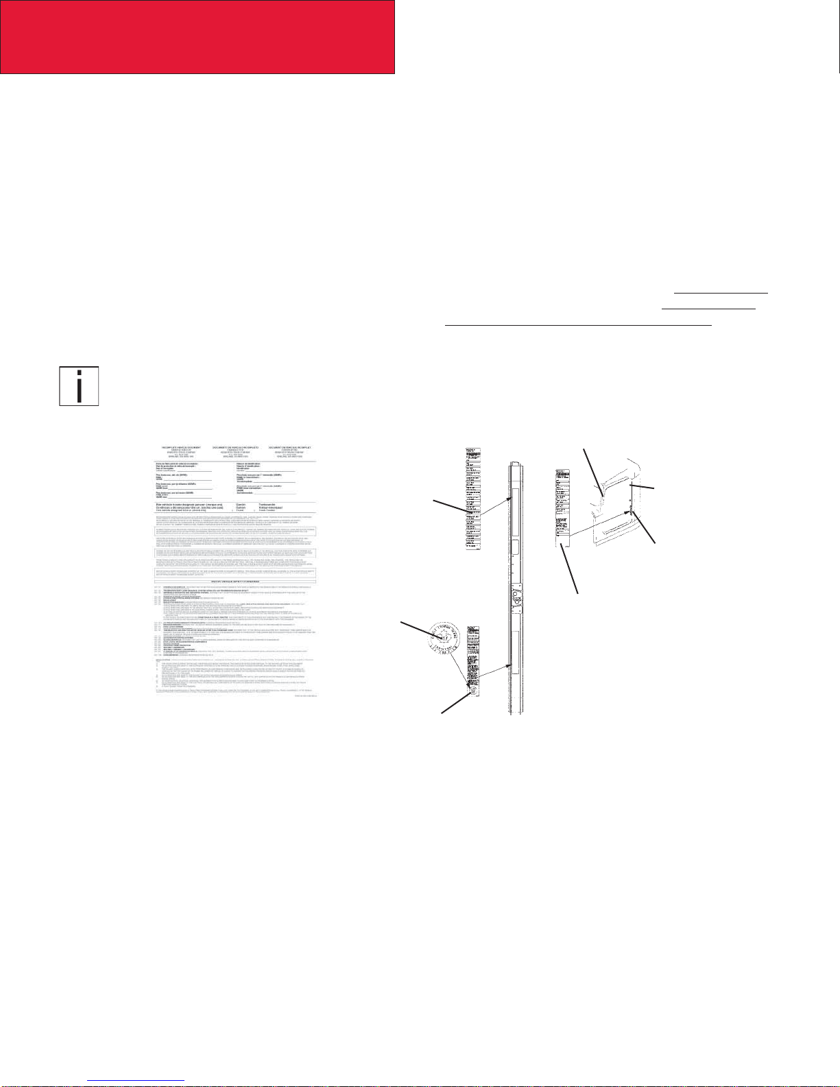
FIGURE 2-1: INCOMPLETE VEHICLE CERTIFICATION DOCUMENT . . . . . . . . . . 2-2
FIGURE 2-2: LOCATIONS OF CERTIFICATION LABELS . . . . . . . . . . . . . . . . . 2-2
FIGURE 2-3: WEST COAST MIRROR OAT SENSOR, . . . . . . . . . . . . . . . . . . . 2-6
FIGURE 2-4: AERODYNAMIC MIRROR OAT SENSOR LOCATION. . . . . . . . . . . . 2-7
FIGURE 2-5: INSTRUMENT CLUSTER FOR T440/T470 USED WITH
EPA2010 EMISSION COMPLIANT ENGINES. . . . . . . . . . . . . . . . 2-7
FIGURE 3-1: PROSPECTOR TURN CIRCLE ANALYSIS . . . . . . . . . . . . . . . . . 3-3
FIGURE 4-1: MEASUREMENT LOCATION OF DEF SUPPLY MODULE (PUMP). . . . . 4-4
FIGURE 4-2: MEASUREMENT LOCATION OF DEF DOSING MODULE (INJECTOR) . . 4-4
FIGURE 4-3: ORIENTATION OF DOSING MODULE . . . . . . . . . . . . . . . . . . . 4-5
FIGURE 4-4: RH UNDER CAB EXHAUST WITH SMALL, MEDIUM, OR LARGETANKS. 4-5
FIGURE 4-5: VERTICAL EXHAUST WITH SMALL, MEDIUM, OR LARGE TANKS.. . . . 4-6
FIGURE 4-6: RH UNDER CAB EXHAUST WITH CLEAR BACK OF CAB TANK. . . . . . 4-7
FIGURE 4-7: VERTICAL WITH CLEAR BACK OF CAB TANK. . . . . . . . . . . . . . . 4-8
FIGURE 4-8: ROUTING DEF LINES AND DEF TRAP . . . . . . . . . . . . . . . . . . . 4-9
FIGURE 4-9: SUPPLY MODULE ALLOWED CLOCKING ANGLES . . . . . . . . . . . . 4-9
FIGURE 4-10: ISOMETRIC VIEW OF RIGHT HAND UNDER DPF AND SCR
WITH SINGLE SOC TAILPIPE . . . . . . . . . . . . . . . . . . . . . . . .4-11
FIGURE 4-11: TOP VIEW OF RIGHT HAND UNDER DPF AND SCR
WITH SINGLE SOC TAILPIPE . . . . . . . . . . . . . . . . . . . . . . . .4-11
FIGURE 4-12: RIGHT VIEW OF RIGHT HAND UNDER DPF AND SCR
WITH SINGLE SOC TAILPIPE . . . . . . . . . . . . . . . . . . . . . . . .4-12
FIGURE 4-13: BACK VIEW OF RIGHT HAND UNDER DPF AND SCR
WITH SINGLE SOC TAILPIPE . . . . . . . . . . . . . . . . . . . . . . . .4-12
FIGURE 4-14: ISOMETRIC VIEW OF RIGHT HAND UNDER DPF AND SCR
WITH SINGLE BACK OF CAB TAILPIPE . . . . . . . . . . . . . . . . . .4-13
FIGURE 4-15: TOP VIEW OF RIGHT HAND UNDER DPF AND SCR
WITH SINGLE BACK OF CAB TAILPIPE . . . . . . . . . . . . . . . . . .4-13
FIGURE 4-16: RIGHT VIEW OF RIGHT HAND UNDER DPF AND SCR
WITH SINGLE BACK OF CAB TAILPIPE . . . . . . . . . . . . . . . . . .4-14
FIGURE 4-17: BACK VIEW OF RIGHT HAND UNDER DPF AND SCR
WITH SINGLE BACK OF CAB TAILPIPE . . . . . . . . . . . . . . . . . .4-14
FIGURE 4-18: ISOMETRIC VIEW OF VERTICAL DPF AND SCR . . . . . . . . . . . . .4-15
FIGURE 4-19: TOP VIEW OF VERTICAL DPF AND SCR . . . . . . . . . . . . . . . . .4-15
FIGURE 4-20: RIGHT VIEW OF VERTICAL DPF AND SCR . . . . . . . . . . . . . . . .4-16
FIGURE 4-21: BACK VIEW OF VERTICAL DPF AND SCR . . . . . . . . . . . . . . . .4-16
FIGURE 4-22: ISOMETRIC VIEW OF RIGHT HAND UNDER DPF AND SCR ON
AEROCAB WITH SINGLE SOC TAILPIPE. . . . . . . . . . . . . . . . . .4-17
FIGURE 4-23: TOP VIEW OF RIGHT HAND UNDER DPF AND SCR ON
AEROCAB WITH SINGLE SOC TAILPIPE. . . . . . . . . . . . . . . . . .4-17
FIGURE 4-24: RIGHT VIEW OF RIGHT HAND UNDER DPF AND SCR ON
AEROCAB WITH SINGLE SOC TAILPIPE. . . . . . . . . . . . . . . . . .4-17
FIGURE 4-25: BACK VIEW OF RIGHT HAND UNDER DPF AND SCR ON
AEROCAB WITH SINGLE SOC TAILPIPE. . . . . . . . . . . . . . . . . .4-18
FIGURE 5-1: DEF TANK DIMENSIONS. . . . . . . . . . . . . . . . . . . . . . . . . . . 5-3
FIGURE 6-1: MINIMUM CLEARANCE BETWEEN TOP OF REARTIRES
AND BODY STRUCTURE OVERHANG.. . . . . . . . . . . . . . . . . . . 6-2
FIGURE 6-2: MINIMUM BACK OF CAB CLEARANCE . . . . . . . . . . . . . . . . . . 6-3
FIGURE 6-3: SPACER BETWEEN FRAME SILL AND BODY RAIL . . . . . . . . . . . . 6-4
FIGURE 6-4: HIGH COMPRESSION SPRING. . . . . . . . . . . . . . . . . . . . . . . 6-4
FIGURE 6-5: RUBBER SPACER BETWEEN BRACKETS BETWEEN THE
MOUNTING BOLT AND UPPER BRACKET. . . . . . . . . . . . . . . . . 6-4

vii 12/09
Figures
FIGURE 6-6: CROSSMEMBER-GUSSET HOLE PATTERN REQUIREMENTS.. . . . . . 6-5
FIGURE 6-7: ACCEPTABLE U-BOLT MOUNTING WITH WOOD AND
FABRICATED SPACERS. . . . . . . . . . . . . . . . . . . . . . . . . . . 6-6
FIGURE 6-8: CLEARANCE SPACE FOR AIR LINES AND CABLES . . . . . . . . . . . 6-7
FIGURE 6-9: EXAMPLE OF FISHPLATE BRACKET AT REAR END OF BODY,
USED WITH U-BOLTS . . . . . . . . . . . . . . . . . . . . . . . . . . . . 6-8
FIGURE 7-1: DETAIL OF FRAME EXTENSION AND JOINT WELDING. . . . . . . . . . 7-2
FIGURE 7-2: FRAME INSERT . . . . . . . . . . . . . . . . . . . . . . . . . . . . . . . 7-3
FIGURE 7-3: COMPARISON OF ORIGINAL, SHORTENED, AND
EXTENDED WHEELBASES.. . . . . . . . . . . . . . . . . . . . . . . . . 7-4
FIGURE 7-4: CROSSMEMBER ADDED WHEN DISTANCE
EXCEEDS 60 INCHES (1524 MM). . . . . . . . . . . . . . . . . . . . . . 7-5
FIGURE 8-1: KENWORTH T440/T470 DASH . . . . . . . . . . . . . . . . . . . . . . . 8-2
FIGURE 8-2: DIESEL EXHAUST FLUID GAUGE . . . . . . . . . . . . . . . . . . . . . 8-2
FIGURE 8-3: MULTIPLEXED INSTRUMENTATION BLOCK DIAGRAM.. . . . . . . . . . 8-3
FIGURE 8-4: CECU LOCATION. . . . . . . . . . . . . . . . . . . . . . . . . . . . . . . 8-4
FIGURE 8-5: INSTRUMENT CLUSTER COMPONENTS . . . . . . . . . . . . . . . . . 8-5
FIGURE 8-6: CVSG GAUGES . . . . . . . . . . . . . . . . . . . . . . . . . . . . . . . 8-6
FIGURE 8-7: FIREWALL AIR JUNCTION BLOCK (VIEW FROM INSIDE OF CAB). . . . 8-7
FIGURE 8-8: AIR FILTER RESTRICTION SENSOR ON FIREWALL
AIR JUNCTION BLOCK (VIEW FROM ENGINE) . . . . . . . . . . . . . . 8-7
FIGURE 8-9: FUEL FILTER RESTRICTION PRESSURE GAUGE SENSOR LOCATION
(TYPICAL) . . . . . . . . . . . . . . . . . . . . . . . . . . . . . . . . . . 8-8
FIGURE 8-10: TELLTALE SYMBOL STANDARD CARDS. . . . . . . . . . . . . . . . . .8-17
FIGURE 8-11: BLANK TELLTALE CARD . . . . . . . . . . . . . . . . . . . . . . . . . .8-18
FIGURE 8-12: TELLTALE ICONS . . . . . . . . . . . . . . . . . . . . . . . . . . . . . .8-19
FIGURE 8-13: KENWORTH SPARE SWITCHES . . . . . . . . . . . . . . . . . . . . . .8-20
FIGURE 8-14: SPARE SWITCH HARNESS . . . . . . . . . . . . . . . . . . . . . . . . .8-21
FIGURE 8-15: SPECIALTY SWITCHES . . . . . . . . . . . . . . . . . . . . . . . . . . .8-22
FIGURE 8-16: SPARE RELAY CONNECTORS . . . . . . . . . . . . . . . . . . . . . . .8-23
FIGURE 8-17: SPARE RELAY HARNESSES . . . . . . . . . . . . . . . . . . . . . . . .8-24
FIGURE 8-18: SPARE BULLET CONNECTORS . . . . . . . . . . . . . . . . . . . . . .8-25
FIGURE 8-19: SPARE PIGTAIL CONNECTOR . . . . . . . . . . . . . . . . . . . . . . .8-26
FIGURE 8-21: CHASSIS POWER DISTRIBUTION CENTER DIMENSIONS . . . . . . . .8-30
FIGURE 8-22: DAYCAB HARDWARE LOCATIONS . . . . . . . . . . . . . . . . . . . . .8-31
FIGURE 8-23: AEROCAB STANDARD HARDWARE LOCATIONS . . . . . . . . . . . . .8-31
FIGURE 8-25: CHASSIS NODE DIMENSIONS . . . . . . . . . . . . . . . . . . . . . . .8-32
FIGURE 8-25: SAE J560 TRAILER CONNECTOR . . . . . . . . . . . . . . . . . . . . . . .
FIGURE 8-26: ISO 3731 TRAILER CONNECTOR . . . . . . . . . . . . . . . . . . . . .8-35
FIGURE 8-27: JUNCTION BOX . . . . . . . . . . . . . . . . . . . . . . . . . . . . . . .8-36
FIGURE 8-31: SNOW PLOW ICON . . . . . . . . . . . . . . . . . . . . . . . . . . . . .8-37
FIGURE 8-32: CIRCUIT LOCATION. . . . . . . . . . . . . . . . . . . . . . . . . . . . .8-37
FIGURE 9-1: CLAMP AND BUTTERFLY CLAMP . . . . . . . . . . . . . . . . . . . . . 9-1
FIGURE 9-2: BUTTERFLYTIE . . . . . . . . . . . . . . . . . . . . . . . . . . . . . . . 9-1
FIGURE 9-3: TIE STRAP. . . . . . . . . . . . . . . . . . . . . . . . . . . . . . . . . . 9-1
FIGURE 9-4: HEAVY DUTY (HD) MOUNT.. . . . . . . . . . . . . . . . . . . . . . . . . 9-2
FIGURE 9-5: DEFINITION OF MEASUREMENTS. . . . . . . . . . . . . . . . . . . . . 9-4
FIGURE A-1: VEHICLE IDENTIFICATION NUMBER (VIN). . . . . . . . . . . . . . . . . A-1
FIGURE A-2: DRIVERS DOOR AND DOOR FRAME LABELS . . . . . . . . . . . . . . A-2
FIGURE A-4: FRONT AXLE IDENTIFICATION. . . . . . . . . . . . . . . . . . . . . . . A-4
FIGURE A-5: REAR AXLE IDENTIFICATION . . . . . . . . . . . . . . . . . . . . . . . A-4

viii
12/09
Tables
TABLE 3-1: ABBREVIATIONS USED . . . . . . . . . . . . . . . . . . . . . . . . . . . . 3-1
TABLE 3-2: TURNING RADIUS. . . . . . . . . . . . . . . . . . . . . . . . . . . . . . . 3-1
TABLE 3-3: AXLE TRACK. . . . . . . . . . . . . . . . . . . . . . . . . . . . . . . . . . 3-4
TABLE 3-4: RIDE HEIGHTS IN INCHES . . . . . . . . . . . . . . . . . . . . . . . . . .3-12
TABLE 3-5: REAR SUSPENSION OPTIONS. . . . . . . . . . . . . . . . . . . . . . . .3-14
TABLE 3-6: REAR SUSPENSION OPTIONS. . . . . . . . . . . . . . . . . . . . . . . .3-15
TABLE 3-7: REAR SUSPENSION OPTIONS. . . . . . . . . . . . . . . . . . . . . . . .3-16
TABLE 3-8: REAR SUSPENSION OPTIONS. . . . . . . . . . . . . . . . . . . . . . . .3-17
TABLE 3-9: REAR SUSPENSION OPTIONS. . . . . . . . . . . . . . . . . . . . . . . .3-18
TABLE 3-10: REAR SUSPENSION OPTIONS. . . . . . . . . . . . . . . . . . . . . . . .3-19
TABLE 3-11: REAR SUSPENSION OPTIONS. . . . . . . . . . . . . . . . . . . . . . . .3-20
TABLE 3-13: REAR SUSPENSION OPTIONS. . . . . . . . . . . . . . . . . . . . . . . .3-22
TABLE 3-14: REAR SUSPENSION OPTIONS. . . . . . . . . . . . . . . . . . . . . . . .3-23
TABLE 3-15: REAR SUSPENSION OPTIONS. . . . . . . . . . . . . . . . . . . . . . . .3-24
TABLE 3-16: REAR SUSPENSION OPTIONS. . . . . . . . . . . . . . . . . . . . . . . .3-25
TABLE 3-17: REAR SUSPENSION OPTIONS. . . . . . . . . . . . . . . . . . . . . . . .3-26
TABLE 3-18: GROUND CLEARANCE FOR FUEL TANKS. . . . . . . . . . . . . . . . . .3-29
TABLE 3-19: GROUND CLEARANCE FOR BATTERY BOXES . . . . . . . . . . . . . . .3-30
TABLE 3-20: GROUND CLEARANCE FOR BATTERY BOXES . . . . . . . . . . . . . . .3-31
TABLE 5-1: ABBREVIATIONS . . . . . . . . . . . . . . . . . . . . . . . . . . . . . . . 5-1
TABLE 5-2: FUEL TANK OVERALL LENGTH (IN) . . . . . . . . . . . . . . . . . . . . . 5-2
TABLE 5-3: BATTERY BOX CENTERFRAME LENGTHS (IN) . . . . . . . . . . . . . . . 5-2
TABLE 5-4: DEF TANKS SYSTEMS . . . . . . . . . . . . . . . . . . . . . . . . . . . . 5-3
TABLE 6-1: SINGLE STEEL RAILS. . . . . . . . . . . . . . . . . . . . . . . . . . . . . 6-2
TABLE 6-2: INSERTED STEEL RAILS . . . . . . . . . . . . . . . . . . . . . . . . . . . 6-2
TABLE 7-1: CUSTOMARY GRADE 8 UNF OR UNC.. . . . . . . . . . . . . . . . . . . . 7-7
TABLE 7-2: U.S.CUSTOMARY – GRADE 8. METRIC CLASS 10.9 . . . . . . . . . . . . 7-7
TABLE 8-1: TELLTALES POSITION AND COLOR . . . . . . . . . . . . . . . . . . . . .8-18
TABLE 8-3: CHASSIS NODE GUIDELINE . . . . . . . . . . . . . . . . . . . . . . . . .8-28
TABLE 8-4: WIRE NUMBER GENERAL CATEGORIES . . . . . . . . . . . . . . . . . .8-33
TABLE 8-6: SAE J560 CONNECTOR. . . . . . . . . . . . . . . . . . . . . . . . . . . .8-34
TABLE 8-7: ISO 3731 CONNECTOR . . . . . . . . . . . . . . . . . . . . . . . . . . . .8-35
TABLE 9-1: EXHAUST – SYSTEM CLEARANCE . . . . . . . . . . . . . . . . . . . . . 9-4
TABLE A-1: MODELYEAR (CODE) DESIGNATIONS. . . . . . . . . . . . . . . . . . . . A-1

Section 1
Introduction
12/09
1-1
This manual was created to provide body builders with appropriate information and guidelines
useful in the body planning and installation process. This information will be helpful when installing
bodies or other associated equipment.
This manual contains appropriate dimensional information, guidelines for mounting bodies, guide-
lines for modifying frames, electrical wiring information, and other information useful in the body
installation process.This manual is specific to chassis with 2010 engines.
The Body Builder Manual can be very useful when specifying a vehicle, particularly when the body
builder is involved in the vehicle definition and ordering process. Early in the process, professional
body builders can often contribute valuable information that reduces the ultimate cost of the body
installation.
In the interest of continuing product development, Kenworth reserves the right to change speci-
fications or products at any time without prior notice.It is the responsibility of the user to ensure
that he is working with the latest released information. Check Kenworth.com for the latest released
version.
If you require additional information or reference materials, please contact your local Kenworth
dealer.

Section 2
Safety & Compliance
12/09
2-1
SAFETY SIGNALS
We’ve put a number of alerting messages in this book. Please read and follow them.They are there for your protection
and information.These alerting messages can help you avoid injury to yourself or others and help prevent costly dam-
age to the vehicle.
Key symbols and “signal words” are used to indicate what kind of message is going to follow. Pay special attention to
comments prefaced by “WARNING”, “CAUTION”, and “NOTE.” Please don’t ignore any of these alerts.
Warnings, cautions, and notes
When you see this word and symbol, the message that follows is especially vital. It signals a
potentially hazardous situation which, if not avoided, could result in death or serious injury.
This message will tell you what the hazard is, what can happen if you don’t heed the warning,
and how to avoid it.
Example:
WARNING! Be sure to use a circuit breaker designed to meet liftgate amperage requirements. An incor-
rectly specified circuit breaker could result in a electrical overload or fire situation. Follow the liftgate
installation instructions and use a circuit breaker with the recommended capacity.
Signals a potentially hazardous situation which, if not avoided, could result in minor or mod-
erate injury or damage to the vehicle.
Example:
CAUTION: Never use a torch to make a hole in the rail. Use the appropriate drill bit.
Provides general information: for example, the note could warn you on how to avoid damaging
your vehicle or how to drive the vehicle more efficiently.
Example:
Note: Be sure to provide maintenance access to the battery box and fuel tank fill neck.
Please take the time to read these messages when you see them, and remember:
WARNING
Indicates a potentially hazardous situation which, if not avoided, could result in death or serious injury.
CAUTION
Signals a potentially hazardous situation which, if not avoided, could result in minor or moderate
injury or damage to the vehicle.
NOTE Useful information that is related to the topic being discussed.
WARNING
CAUTION
NOTE

Section 2
Safety & Compliance
12/09 2-2
FEDERAL MOTOR VEHICLE SAFETY
STANDARDS COMPLIANCE
As an Original Equipment Manufacturer (OEM), Kenworth Truck Co. ensures that our products comply with all applicable
U.S.or Canadian Federal MotorVehicle Safety Standards. However, the fact that this vehicle has no fifth wheel and that a
Body Builder (Intermediate or Final Stage Manufacturer) will be doing additional modifications means that the vehicle was
incomplete when it left the build plant.See next section and Appendix A for additional information.
IncompleteVehicle Certification
An Incomplete Vehicle Document is shipped with the vehicle, certifying that the vehicle is not complete. See Figure 2–1.
In addition, affixed to the driver’s side door frame or edge is an Incomplete Vehicle Certification label. See Figure 2–2. For
further information on Vehicle Certification and Identification, see APPENDIX A “VEHICLE IDENTIFICATION.”
These documents list the U.S.or Canadian Federal MotorVehicle Safety Standard regulations that the
vehicle complied with when it left the build plant.You should be aware that if you add, modify or alter any
of the components or systems covered by these regulations, it is your responsibility as the Intermediate or
Final Stage Manufacturer to ensure that the complete vehicle is in compliance with the particular regula-
tions upon completion of the modifications.
FIGURE 2-1. Incomplete Ve-
hicle Certification Document FIGURE 2-2. Locations of Certifica-
tion Labels - Driver’s Door and Frame
NOTE
U.S.EPA Noise Label (U.S. registered vehicles only)
Final Stage Manufacturer
Label to be Installed by
Final Stage Manufacturer
Chassis Serial
Number
Major Components and
Weights Label
Incomplete Vehicle
Certification Label
Safety Mark (Canadian
Registry Only)
Tire, Rim and
Weight Rating
Data label
As the Intermediate or Final Stage Manufacturer, you should retain the Incomplete Vehicle Document for your records. In
addition, you should record and retain the manufacturer and serial number of the tires on the vehicle.Upon completion
of the vehicle (installation of the body and any other modifications), you should affix your certification label to the vehicle
as required by Federal law.This tag identifies you as the “Intermediate or Final Stage Manufacturer” and certifies that the
vehicle complies with Federal Motor Vehicle Safety Standards. (See Figure 2–2.) Be advised that regulations affecting the
intermediate and final stage manufacturer may change without notice. Ensure you are referencing the most updated copy
of the regulation during the certification and documentation processes.
In part, if the final stage manufacturer can complete and certify the vehicle within the instruction in the incomplete vehicle
document (IVD) the certification label would need a statement that reads, “This vehicle has been completed in accordance
with the prior manufacturers‚ IVD where applicable.This vehicle conforms to all applicable Federal Motor Vehicle Safety
Standards [and Bumper and Theft Prevention Standards if applicable] in effect in (month, year).”
However, if the vehicle can not be completed and certified with in the guidance provided in the IVD, the final stage manu-
facturer must ensure the vehicle conforms to all applicable Federal Motor Vehicle Safety Standards (FMVSS).The final
stage manufactures certification label would need a statement that reads, “This vehicle conforms to all applicable Federal
Motor Vehicle Safety Standards [and Bumper andTheft Prevention Standards if applicable] in effect in (month, year).”

Section 2
Safety & Compliance
12/09
2-3
These statements are just part of the changes to the new certification regulation. Please refer to the Feb 15, 2005
final rule for all of the details related to this regulation.You can contact NTEA Technical Services Department at
1-800-441-NTEA for a copy of the final rule (DocID 101760).
For Canadian final stage manufacturers see:
http://www.gazette.gc.ca/archives/p2/2002/2002-02-13/html/sor-dors55-eng.html; and
http://www.tc.gc.ca/acts-regulations/regulations/crc-c1038/menu.htm for the regulations.
Or contact:
Transport Canada
Tower C, Place de Ville, 330 Sparks Street
Ottawa, Ontario K1A 0N5
(613) 990-2309
TTY: 1-888-675-6863
Noise and Emissions Requirements
This truck may be equipped with specific emissions control components/systems* in order to
meet applicable Federal and California noise and exhaust emissions requirements.Tampering
with these emissions control components/systems* is against the rules that are established by the
U.S Code of Federal Regulations, Environment Canada Regulations and California Air Resources
Board (CARB).These emissions control components/systems* may only be replaced with original
equipment parts.
Modifying (i.e.altering, substituting, relocating) any of the emissions control components/sys-
tems defined above will affect the noise and emissions performance/certification. If modifications
are required, they must first be approved by the engine manufacturer. Unapproved modifications
could negatively effect emissions performance/certification.There is no guarantee that proposed
modifications will be approved.
Contact the engine manufacturer for any requirements and restrictions prior to any modifications.
For Cummins Contact: Please call 1-800-DIESELS or contact your local Cummins Distributor Reference• AEB 21.102.
It is possible to relocate the DEF tank, however the relocation requirements need to be followed. Any variance from the
relocation requirements may cause the emissions control components/systems to operate improperly potentially resulting
in engine de-rate.See page 4-3 for relocation requirements.
Some 2010 engine emissions certified vehicles will be equipped with an On-Board Diagnostics
(OBD) system.The OBD system is designed to detect malfunctions of any engine or vehicle
component that may increase exhaust emissions or interfere with the proper performance of the
OBD system itself.
The OBD system consists of computer program on one or more of the vehicle’s Electronic Control
Units (ECUs).This program uses information from the control system and from additional sensors
to detect malfunctions.When a malfunction is detected, information is stored in the ECU(s) for
diagnostic purposes. A Malfunction Indicator Light (MIL) is illuminated in the dash to alert the
driver of the need for service of an emission-related component or system.
NOTE
NOTE

Section 2
Safety & Compliance
12/09 2-4
To ensure compliance to emissions regulations, the final configuration of certain features of the completed vehicle
must meet specific requirements.This section describes requirements relevant for only the most common or critical modifi-
cations done by body builders.For a complete description of acceptable modifications, see the application
guidance available from the manufacturer of the engine installed in the chassis.
Fuel System
The following are highlights of some of the more common or critical aspects of this system.
The overall system restriction may not exceed the restriction limitations set forth by the engine manufacturer for both
supply and return.
Ensure that fuel lines are not pinched or can potentially be damaged when installed between body and frame•
Fuel lines must be routed and secured without dips or sags•
There must be easy access to filter(s) and fill cap•
The tank vent may not obstructed•
Added accessories (heaters, generators) cannot introduce air into system•
Fuel tank must be located so that the full level is not above cylinder head•
“Ultra Low Sulfur Fuel Only” labels must be present on the dash and fuel fill•
Modification of the pressure side secondary filter and plumbing is not allowed without engine manufacturer• approval
Body installation of fuel tank or routing of lines must not cause significant increase in fuel temperature•
Fuel hoses shall meet or exceed OEM supplied hose material construction specifications•
Compressed Air System
The following are highlights of some of the more common or critical aspects of this system.
Air system modification must meet applicable FMVSS regulations•
Compressed Air tank may not be modified (exception – addition or removal of fittings or relocation of the tank)•
Added devices or bodywork may not interfere with or rub air lines•
Air supply to the engine doser may not be restricted or disconnected•
Air lines should be routed, protected from heat, and properly secured to prevent damage from other• components
Care should be taken so that air lines do not rub against other components•
Care should be taken to protect the air system from heat sources.•
Exhaust and Exhaust After-treatment System
The following are highlights of some of the more common or critical aspects of this system.
The following after-treatment and exhaust system components may not be modified:•
DPF assembly• SCR Catalyst assembly• Exhaust pipes between the engine and after-treatment devices (DPF, SCR Catalyst) and between• after-treatment devices

Section 2
Safety & Compliance
12/09
2-5
NO• xSensor
The following modifications may only be done within the guidelines of the “DEF System Relocation Guide.”•
Modifications to Diesel Exhaust Fluid (DEF) throttle, suction, or pressure lines• Modification or relocation of the DEF tank• Modification of coolant lines to and from the DEF tank•
All DEF and coolant lines should be routed, protected, and properly secured to prevent damage during vehicle• operation or other components
If relocation of the DCU or ACM is necessary, use existing frame brackets and mount inside of frame flanges• where necessary. Do not extend the harnesses
Exhaust pipes between the engine and after-treatment devices or between after-treatment devices may not be• modified or replaced
The DPF, the SCR catalyst, or their mounting may not be modified•
The NO• xsensor may not been relocated or altered in any way
Exhaust pipes used for tailpipes/stacks must be properly sized, and must prevent water from entering the• exhaust system
Ensure adequate clearance between the exhaust and body panels, hoses, and wire harnesses•
The body in the vicinity of the DPF must be able to withstand temperatures up to 400°C (750°F)•
Do not add thermal insulation to the external surface of the DPF•
The SCR water drain hole may not be blocked•
Allow adequate clearance (25mm (1 inch)) for servicing the DPF sensors, wiring, and clamped joints•
Drainage may not come in contact with the DPF, SCR catalyst, sensors or wiring•
Allow sufficient clearance for removing sensors from DPF.Thermistors require four inches.Other sensors• require one inch
Wiring should be routed, protected from heat, and properly secured to prevent damage from• other components
The exhaust system from an auxiliary power unit (APU) must not be connected to any part of the vehicle• after-treatment system or vehicle tail pipe.
Cooling System
The following are highlights of some of the more common or critical aspects of this system.
Modifications to the design or locations of fill or vent lines, heater or defroster core, and surge tank are not• recommended
With the exception of post-thermostat installation, additional accessories plumbed into the engine cooling• system are not permitted, and may void vehicle warranty
Coolant level sensor tampering will void warranty•
When installing auxiliary equipment in front of the vehicle, or additional heat exchangers, ensure that• adequate air flow is available to the vehicle cooling system. Refer to engine manufacturer application
guidelines for further detail
When installing FEPTO drivelines, the lower radiator anti-recirculation seal must be retained with FEPTO• driveline clearance modification only

Section 2
Safety & Compliance
12/09 2-6
Changes made to cooling fan circuit and controls are not allowed, with the exception of AC minimum fan on• time parameter
See owner’s manual for appropriate winter front usage•
Electrical System
The following are highlights of some of the more common or critical aspects of this system.
Electrical harnesses providing battery power and electronic control signals to engine and emissions control/• vehicle OBD components including datalinks may not be spliced.These emissions control/vehicle OBD
components include the following:
throttle pedal• vehicle speed sensor• after-treatment wiring•
If the alternator or battery is substituted, it must meet the requirements of the engine manufacture’s guide-• lines.This includes alternator ground voltage drop and alternator ground cable effectiveness.See the engine
manufacture’s guidelines for recommended test procedure. Additionally the maximum voltage differential and
the peak-peak voltage differential between the engine ECM block ground stud and battery negative terminal
may not exceed 500 mV under any combination of loads or operating conditions.
Installation of aftermarket transfer-cases must address the vehicle speed sensor position.The standard posi-• tion of the speed sensor is at the transmission tail shaft.When a transfer-case is added it is best to relocate
the sensor to the axle side output shaft of the transfer-case.This is typically accomplished by adding a tone
wheel into the driveline yoke assembly.
Wiring extensions for the after-treatment wiring are available for relocating the DEF tank from your dealer via• Paccar Parts. For relocation of DEF tank, refer to the after-treatment section of this manual.
The emission system requires an accurate Outside Air Temperature (OAT) reading in order to properly run• its control algorithms.The OAT sensor is located in the driver’s side mirror assembly on Kenworth trucks and
is shown in the figures below. If the body builder needs to modify the mirror assembly in any way, it is im-
portant the OAT sensor stay positioned on the mirror assembly. Running the vehicle without the OAT sensor
connected will cause the MIL lamp to illuminate.If needed, a replacement sensor can be ordered from your
Kenworth dealer.
FIGURE 2-3: West Coast Mirror OAT sensor, located in overmold on mirror harness.

Section 2
Safety & Compliance
12/09
2-7
FIGURE 2-4: Aerodynamic Mirror OAT Sensor Location
Coolant Sensor considerations are given in the Cooling section above•
The OBD/Diagnostic connector port is located below the dash to the left of the steering wheel.This connector• or its location may not be changed.
Vehicles using EPA 2010 compliant engines must be equipped with a Malfunction Indicator Lamp (MIL) lamp.• This lamp is required to be an engine outline symbol as defined by ISO (International Standards Organiza-
tion).The figure below shows the instrument cluster and MIL lamp position. Note this lamp location is fixed
with respect to the controls and its location may not be changed if you are updating the warning lamp cards.
FIGURE 2-5: Instrument Cluster forT440/T470 used with EPA2010 Emission compliant
engines.The Check Engine lamp is symbol 21 and the MIL is symbol 8.
In addition to the sensors and lamps above, the emission system also depends on signals from the exhaust• DPF (Diesel Particulate Filter), SCR (Selective Catalytic Reduction), and NOx sensor.Wiring between these
devices, the Dosing Control Unit (DCU) and engine ECM should not be tampered with or altered in any way.

Section 2
Safety & Compliance
12/09 2-8
Air Intake System
The following are highlights of some of the more common or critical aspects of this system.
The air intake screen may not be blocked, either fully or partially•
Modification to the air intake system may not restrict airflow. For example, pipe diameter may not be reduced•
All sensors must be retained in existing locations•
To retain system seal, proper clamp torque must be used. Refer to service manual for proper clamp torque•
Charge Air Cooler System
The following are highlights of some of the more common or critical aspects of this system.
The Charge Air Cooler may not be modified•
The installation of engine overspeed shutdown devices must not introduce restriction in the intake system•
All plumbing associated with the charge air cooler may not be modified•

Section 3
Dimensions
12/09
3-1
DIMENSIONS
This section has been designed to provide enough information to successfully layout chassis in the body planning
process.Optional equipment may not be depicted. Please contact your local Kenworth dealer if more dimensional
information is desired.
ABBREVIATIONS
Throughout this section, and in other sections as well, abbreviations are used to describe certain characteristics on your
vehicle.The chart below lists the abbreviated terms used.
TABLE 3-1. Abbreviations Used
AF AFTER FRAME – FRAME RAIL OVERHANG BEHIND REAR AXLE OR MEASURED FROM CENTERLINE OFTANDEM
CA BACK OF CABTO CENTERLINE OF REAR AXLE OR CENTERLINE OFTANDEMS ON TANDEM SUSPENSION
EOF FRAME RAIL OVERHANG BEHIND REAR AXLE – MEASURED FROMTHE CENTERLINE OF TANDEMS
FS FRONT SUSPENSION HEIGHT
RS REAR SUSPENSION HEIGHT
WB WHEELBASE
SOC SIDE OF CAB
BOC BACK OF CAB
TURNING RADIUS
Approximate turning radius specifications are listed in the following tables as a general guide. It is important to note that
optional components may alter the results.
TABLE 3-2. Turning Radius
Model Steering Gear Front Axle FrontWheel FrontTire Rear
Suspension Wheel Base Est Curb to
CurbTurning
Radius (ft)
T440/T470 Single
TAS 65 Dana Spicer
E-1202I 12K Accuride 28487
22.5 X 8.25
Bridgestone
R287
295/75R22.5
Tandem
52” Axle
Spacing
181 28
193 29.5
201 30.5
213 32
220 33
232 34.5
240 35.5
252 37
260 38
272 39.5
280 40.5
291 42
303 43.5
323 46
331 47
TABLE 3-2 CONTINUES ON NEXT PAGE…

Section 3
Dimensions
12/09 3-2
Model Steering Gear Front Axle FrontWheel FrontTire Rear
Suspension Wheel Base Est Curb to
CurbTurning
Radius (ft)
T440/T470 Dual
TAS 65
Dana Spicer
D2000 20K
Standard Track
Alcoa 82365
22.5 X 12.25
Bridgestone
M844
425/65R22.5
Tandem
52” Axle
Spacing
181 31.5
193 33.5
201 34.5
213 36.5
220 37.5
232 39
240 40
252 42
260 43
272 45
280 46
291 47.5
303 49.5
323 52.5
331 53.5
TABLE 3-2 CONTINUED

Section 3
Dimensions
12/09
3-3
ProspectorTurn Circle Analysis:
Please see Figure 3-2 as an example of Kenworth’s turn circle calculation made in Prospector for your specific chassis.
Your local Kenworth dealer can provide this information to you.
FIGURE 3-1. Prospector Turn Circle Analysis
Please consult your local Kenworth Dealer for this information, as it is chassis specific.
T470
T470

Section 3
Dimensions
12/09 3-4
KENWORTH AXLETRACK/TIREWIDTH SUMMARY
Axle - Drive Wheel Tire Configuration Track Dim ”A” Overall Width Dim ”B”
Dana Spicer D46-170(H)(P)
46K Dual Alcoa 88364
22.5X8.25 BR M726EL
11R22.5 4-4 73.3” 97.8”
Dana Spicer D46-170(H)(P)
46K Dual Alcoa 98364
24.5X8.25 BR M726EL
11R24.5 4-4 73.6” 98.0”
Dana Spicer D46-170W(H)(P)
46K Dual Wide Track Alcoa 88364
22.5X8.25 BR M726EL
11R22.5 4-4 79.2” 103.7”
Dana Spicer D46-170W(H)(P)
46K Dual Wide Track Alcoa 98364
24.5X8.25 BR M726EL
11R24.5 4-4 79.5” 103.9”
Dana Spicer D46-170(H)(P)
46K Dual Alcoa 82360
22.5X12.25 BR M844F
425/65R22.5 2-4 72.7” 88.9”
Dana Spicer D46-170W(H)(P)
46K Dual Wide Track Alcoa 82360
22.5X12.25 BR M844F
425/65R22.5 2-4 78.7” 94.9”
Axle - Steer Wheel Tire Brake DrumType Track Dim ”A” Overall Width Dim ”B”
Dana Spicer E-1322I 13.2K Alcoa 98364
24.5X8.25 BR R250F
11R24.5 Cast 80.2” 91.0”
Dana Spicer E-1322W 13.2K Alcoa 98364
24.5X8.25 BR R250F
11R24.5 Cast 82.2” 93.0”
Dana Spicer D2000 20K Alcoa 82365
24.5X12.25 BR M844F
425/65R22.5 Cast 86.5” 102.7”
Dana Spicer D2000 20K Alcoa 82364
24.5X12.25 BR M844F
425/65R22.5 Cast 82.6” 98.8”
Axle - Pusher Non-Steerable Wheel Tire Wheel Orientation “Track Dim ”A” “OverallWidth Dim ”B”
NS PSHR:WCAL ATLAS
Std Track (72.5”) 16K GAWR Alcoa 82365
24.5X12.25 BR M844F
425/65R22.5 Default-
Same as RR 79.4” 95.6”
NS PSHR:WCAL ATLAS
Wide Track (77.5”) “Alcoa 82365
24.5X12.25 BR M844F
425/65R22.5 Option
Same as FR 71.1” 87.3”
TABLE 3-3. Axle Track
AXLETRACK ANDTIRE WIDTH
The dimensions provided in this section are representative of some typical product combinations. The purpose of this sec-
tion is to demonstrate some of the typical dimensions.
Axle Track:The distance between the dual tire centerlines on a dual tire arrangement or the distance between the tire• centerlines on a single tire arrangement.
Width:The distance over the outermost tire sidewall to sidewall.•
These dimensions may be significant to the following:
Appearance relative to other tires and chassis mounted equipment.•
Load carrying capacity. Different wheel disc offset can have a positive or negative impact on the axle carrying capac-• ity of the axle.
This manual suits for next models
1
Table of contents
Other Kenworth Truck manuals