KEPCO BOP 6-125MG/ME User manual

©2018, KEPCO, INC
Data subject to change without notice 228-1692 REV 8 1
QUICK START GUIDE
KEPCO
KEPCO, INC. 131-38 SANFORD AVENUE FLUSHING, NY. 11355 U.S.A. TEL (718) 461-7000FAX (718) 767-1102
http://www.kepcopower.com email: hq@kepcopower.com
An ISO 9001 Company.
BOP
1KW
-MG/ME
BOP 1KW-MG/ME POWER SUPPLY
This guide gives a brief introduction to the BOP 1KW-MG/ME Power supply, shows simple load connections, and allows you to
verify the power supply is working. The guide also shows you how to use the front panel controls to perform the most commonly
used functions.
BOP 1KW models with MG and ME suffixes are identical except that the MG units have a factory-installed GPIB interface
and in the ME units the GPIB interface is replaced with a LAN interface. Unless otherwise noted this guide applies to both
models.
ACCESSING MANUALS. First determine your Firmware Version (see below), then download the BOP 1KW-MG, ME
applicable Operator’s Manual from
www.kepcopower.com/support/opmanls.htm#bop-1k
Refer to the BOP 1KW-MG/ME Operator’s Manual for full specifications, installation considerations and operating instruc-
tions, including an Installation/Operation Summary which includes hyperlinked references to detailed procedures, but
which can be printed as a handy reference. The BOP 1KW-MG/ME Operator’s Manual also includes a full description of
the digital interfaces and the SCPI command language.
FIRMWARE VERSION. Refer to www.kepcopower.com/support/bophifirm.htm to determine which firmware ver-
sion is installed.
ACCESSING DRIVERS. Drivers are accessed from www.kepcopower.com/drivers/drivers-dl3.htm.

2228-1692 REV 8 090418
KEPCO, INC. 131-38 SANFORD AVENUE FLUSHING, NY. 11355 U.S.A. TEL (718) 461-7000FAX (718) 767-1102
http://www.kepcopower.com email: hq@kepcopower.com
CONTENTS
I — DESCRIPTION.
The BOP 1KW-MG/ME Series hereafter referred to
as BOP, are true 4-quadrant programmable voltage
and current power supplies, meaning they are capa-
ble of both sourcing and sinking power (see Figure
61). These bipolar power supplies pass smoothly
through zero without switching to provide true ± volt-
age and ± current. These BOP power supplies use
switch mode technology for low dissipation. A bi-
directional, isolating, a-c input power factor correct-
ing (PFC) circuit recuperates energy sinked from an
active load and sends it back into the line to maintain
low dissipation.
These BOP power supplies are controlled digitally
from a menu-driven front-panel keypad or one of the
remote digital interfaces (GPIB or RS 232 on MG
models, LAN or RS 232 on ME models) to set volt-
age and current and the four protection limits (+volt-
age, –voltage, +current and –current.) A front panel
rotary adjuster allows real-time adjustment of the
output. A large LCD displays the mode of operation,
the settings, and the actual output voltage and cur-
rent. Additionally, these BOP models can be
remotely controlled by an analog ±10V input for the
main channel (voltage or current), and a +1 to +10V
input for the limit channels.
BOP models are suitable for driving inductive loads
such as large magnets or motors, and for exercising
batteries. They are also suitable for characterizing
solar cell arrays, and powering many electrochemi-
cal reactions.
II — UNPACKING.
This instrument has been thoroughly inspected and
tested prior to packing and is ready for operation.
After careful unpacking, inspect for shipping damage
before attempting to operate. Perform the “Installa-
tion.” on page 5. If any indication of damage is
found, file an immediate claim with the responsible
transport service.
Description. . . . . . . . . . . . . . . . . . . . . . . . . . . . . . . . . . . . . . . . . . . . . . . . . . . . . . . . . . . . . . . . . . . . . . . . . . . . . . . . . . . . . . . . . . 2
Unpacking. . . . . . . . . . . . . . . . . . . . . . . . . . . . . . . . . . . . . . . . . . . . . . . . . . . . . . . . . . . . . . . . . . . . . . . . . . . . . . . . . . . . . . . . . . . 2
Equipment Supplied. . . . . . . . . . . . . . . . . . . . . . . . . . . . . . . . . . . . . . . . . . . . . . . . . . . . . . . . . . . . . . . . . . . . . . . . . . . . . . . . . . . 3
Safety. . . . . . . . . . . . . . . . . . . . . . . . . . . . . . . . . . . . . . . . . . . . . . . . . . . . . . . . . . . . . . . . . . . . . . . . . . . . . . . . . . . . . . . . . . . . . . 3
Preliminary Operational Check. . . . . . . . . . . . . . . . . . . . . . . . . . . . . . . . . . . . . . . . . . . . . . . . . . . . . . . . . . . . . . . . . . . . . . . . . . . 3
Accessories. . . . . . . . . . . . . . . . . . . . . . . . . . . . . . . . . . . . . . . . . . . . . . . . . . . . . . . . . . . . . . . . . . . . . . . . . . . . . . . . . . . . . . . . . 5
Installation. . . . . . . . . . . . . . . . . . . . . . . . . . . . . . . . . . . . . . . . . . . . . . . . . . . . . . . . . . . . . . . . . . . . . . . . . . . . . . . . . . . . . . . . . . 5
Input Connections. . . . . . . . . . . . . . . . . . . . . . . . . . . . . . . . . . . . . . . . . . . . . . . . . . . . . . . . . . . . . . . . . . . . . . . . . . . . . . . . 5
Load Connections. . . . . . . . . . . . . . . . . . . . . . . . . . . . . . . . . . . . . . . . . . . . . . . . . . . . . . . . . . . . . . . . . . . . . . . . . . . . . . . . 5
Local Sensing (Factory Default). . . . . . . . . . . . . . . . . . . . . . . . . . . . . . . . . . . . . . . . . . . . . . . . . . . . . . . . . . . . . . . . . . . . . . 6
Remote Sensing Select. . . . . . . . . . . . . . . . . . . . . . . . . . . . . . . . . . . . . . . . . . . . . . . . . . . . . . . . . . . . . . . . . . . . . . . . . . . . 6
Analog I/O Connections. . . . . . . . . . . . . . . . . . . . . . . . . . . . . . . . . . . . . . . . . . . . . . . . . . . . . . . . . . . . . . . . . . . . . . . . . . . . 6
Trigger Connections. . . . . . . . . . . . . . . . . . . . . . . . . . . . . . . . . . . . . . . . . . . . . . . . . . . . . . . . . . . . . . . . . . . . . . . . . . . . . . . 6
GPIB Connections (MG SUFFIX). . . . . . . . . . . . . . . . . . . . . . . . . . . . . . . . . . . . . . . . . . . . . . . . . . . . . . . . . . . . . . . . . . . . 6
LAN Connections (ME SUFFIX ONLY). . . . . . . . . . . . . . . . . . . . . . . . . . . . . . . . . . . . . . . . . . . . . . . . . . . . . . . . . . . . . . . . 6
FINDING KEPCO POWER SUPPLIES ON THE LAN. . . . . . . . . . . . . . . . . . . . . . . . . . . . . . . . . . . . . . . . . . . . . . . . . . . . . 6
RS 232 Connections. . . . . . . . . . . . . . . . . . . . . . . . . . . . . . . . . . . . . . . . . . . . . . . . . . . . . . . . . . . . . . . . . . . . . . . . . . . . . . 7
Operation. . . . . . . . . . . . . . . . . . . . . . . . . . . . . . . . . . . . . . . . . . . . . . . . . . . . . . . . . . . . . . . . . . . . . . . . . . . . . . . . . . . . . . . . . . . 9
Turning The Power Supply On. . . . . . . . . . . . . . . . . . . . . . . . . . . . . . . . . . . . . . . . . . . . . . . . . . . . . . . . . . . . . . . . . . . . . . . 9
Accessing the Menus. . . . . . . . . . . . . . . . . . . . . . . . . . . . . . . . . . . . . . . . . . . . . . . . . . . . . . . . . . . . . . . . . . . . . . . . . . . . . . 9
How to Modify a Parameter. . . . . . . . . . . . . . . . . . . . . . . . . . . . . . . . . . . . . . . . . . . . . . . . . . . . . . . . . . . . . . . . . . . . . . . . 10
Adjusting LCD Brightness, contrast and Background . . . . . . . . . . . . . . . . . . . . . . . . . . . . . . . . . . . . . . . . . . . . . . . . . . . . 11
Enabling/Disabling Audible Beeps . . . . . . . . . . . . . . . . . . . . . . . . . . . . . . . . . . . . . . . . . . . . . . . . . . . . . . . . . . . . . . . . . . 11
Setting Voltage or Current Mode . . . . . . . . . . . . . . . . . . . . . . . . . . . . . . . . . . . . . . . . . . . . . . . . . . . . . . . . . . . . . . . . . . . 11
Programming Voltage or Current and Associated Protect Limits . . . . . . . . . . . . . . . . . . . . . . . . . . . . . . . . . . . . . . . . . . . 11
Software Limits. . . . . . . . . . . . . . . . . . . . . . . . . . . . . . . . . . . . . . . . . . . . . . . . . . . . . . . . . . . . . . . . . . . . . . . . . . . . . . . . . 12
Changing Main Channel Software limit.. . . . . . . . . . . . . . . . . . . . . . . . . . . . . . . . . . . . . . . . . . . . . . . . . . . . . . . . . . . 12
Determining How the Unit Responds when Output is OFF (Load Type) . . . . . . . . . . . . . . . . . . . . . . . . . . . . . . . . . . . . . 12
Configure Load Type. . . . . . . . . . . . . . . . . . . . . . . . . . . . . . . . . . . . . . . . . . . . . . . . . . . . . . . . . . . . . . . . . . . . . . . . . . . . . 14
Enabling/disabling Output Power. . . . . . . . . . . . . . . . . . . . . . . . . . . . . . . . . . . . . . . . . . . . . . . . . . . . . . . . . . . . . . . . . . . . 14
Additional Features. . . . . . . . . . . . . . . . . . . . . . . . . . . . . . . . . . . . . . . . . . . . . . . . . . . . . . . . . . . . . . . . . . . . . . . . . . . . . . . . . . . 14
BOP 1KW Outline Dimensions . . . . . . . . . . . . . . . . . . . . . . . . . . . . . . . . . . . . . . . . . . . . . . . . . . . . . . . . . . . . . . . . . . . . . . . . . 15

090418 228-1692 REV 8 3
KEPCO, INC. 131-38 SANFORD AVENUE FLUSHING, NY. 11355 U.S.A. TEL (718) 461-7000FAX (718) 767-1102
http://www.kepcopower.com email: hq@kepcopower.com
.
III — EQUIPMENT SUPPLIED.
See Table 2. IV — SAFETY. See Table 3
V — PRELIMINARY OPERATIONAL CHECK.
A simple operational check after unpacking and
before equipment installation is advisable to ascer-
tain whether the power supply has suffered damage
resulting from shipping.
1. With POWER switch set to off position, connect
the power supply to source power (see “Input
Connections.” on page 5.
2. With no load connected, set POWER switch to
the ON position. Each time the unit is turned on
an internal self-test is performed. If all tests pass,
the unit goes into the default mode. If a failure
occurs, the failure is displayed. Figure 5 shows
the factory-configured power on defaults dis-
played on the LCD.
3. Connect a digital voltmeter (DVM) (resolution and
accuracy of 0.01% or better) to the OUT S and
COM S terminals at the rear panel terminal block.
4. Use the keypad to enter the rated maximum volt-
age of the power supply (e.g., enter 36 for a
model BOP 36-28MG) and press ENTER. If
STANDBY indicator is lit, press STANDBY key.
5. Verify DVM voltage reading agrees with pro-
grammed voltage within 0.03% of rated maximum
voltage and agrees with displayed voltage on
LCD within 0.05% of rated maximum voltage.
TABLE 1. BOP 1KW-MG/ME MODEL PARAMETERS
Model (1)
d-c Output Range Closed Loop Gain Output Impedance
Voltage (2)
(V d-c) Current
(A d-c)
Voltage
Channel
GV(V/V)
Current
Channel
GI(A/V)
Voltage Mode
(Series R - L) Current Mode
(Parallel R - C)
Rd-c
(mOhms) L
(H) Rd-c
(Ohms) C
(F)
1000 WATT MODELS
BOP 6-125MG/ME 0 to ±6 0 to ±125 0.6 12.5 0.05 1.5 24 1150
BOP 10-100MG/ME 0 to ±10 0 to ±100 1.0 10.0 0.1 2.0 50 1100
BOP 10-75MG/ME 0 to ±10 0 to ±75 1.0 7.5 0.13 2.0 67 976
BOP 20-50MG/ME 0 to ±20 0 to ±50 2.0 5.0 0.40 8.3 200 371
BOP 25-40MG/ME 0 to ±25 0 to ±40 2.5 4.0 0.63 15.8 313 165
BOP 36-28MG/ME 0 to ±36 0 to ±28 3.6 2.8 1.30 25 640 103
BOP 50-20MG/ME 0 to ±50 0 to ±20 5.0 2.0 2.50 50 1250 55
BOP 72-14MG/ME 0 to ±72 0 to ±14 7.2 1.4 5.14 104 2570 33
BOP 100-10MG/ME 0 to ±100 0 to ±10 10.0 1.0 10.0 163 5000 16
(1) Models with MG suffix include GPIB and RS 422 digital interfaces. Models with ME suffix include LAN and RS 422 digital interfaces.
(2) When connecting active loads, the steady-state voltage of the active load must not exceed the maximum voltage rating of the BOP.
Otherwise the overvoltage protection will shut down the power supply.
TABLE 2. EQUIPMENT SUPPLIED
ITEM FUNCTION PART NUMBER
Source Power Entry
mating connector Mateswith sourcepower
entry connector 142-0381
(Kepco) (IEC
320)
PAR/SER CONTROL
- IN mating connector Mates with PAR/SER
CONTROL - IN port to
allow access to pins
required for calibration
142-0488
(Kepco)
TABLE 3. SAFETY SYMBOLS
SYMBOL MEANING
CAUTION: RISK OF ELECTRIC SHOCK.
CAUTION: REFER TO REFERENCED PROCE-
DURE.
WARNING INDICATES THE POSSIBILITY OF BODILY
INJURY OR DEATH.
CAUTION INDICATES THE POSSIBILITY OF EQUIPMENT
DAMAGE.
!

4228-1692 REV 8 090418
KEPCO, INC. 131-38 SANFORD AVENUE FLUSHING, NY. 11355 U.S.A. TEL (718) 461-7000FAX (718) 767-1102
http://www.kepcopower.com email: hq@kepcopower.com
FIGURE 1. BOP OUTPUT CHARACTERISTICS

090418 228-1692 REV 8 5
KEPCO, INC. 131-38 SANFORD AVENUE FLUSHING, NY. 11355 U.S.A. TEL (718) 461-7000FAX (718) 767-1102
http://www.kepcopower.com email: hq@kepcopower.com
VI — ACCESSORIES. See Table 4.
VII — INSTALLATION.
Install units either on a bench or in a 19 inch-wide
rack. For rack mounting: remove four feet first; rack
must provide support at the rear). Optional slides
may be used. Leave the front and rear panels clear
of obstructions to ensure adequate cooling. For par-
allel, series and master-slave configurations, refer to
the Operator’s Manual.
INPUT CONNECTIONS. Source power is con-
nected to the power supply via three-wire input
power using the source power mating connector
supplied (see Table 4). This power supply operates
from single phase a-c mains power (or between two
phases of 3-phase a-c mains power), 230V, 50/60Hz
nominal (range: 176 - 264V, 47-63Hz) without any
need for range selection. The user must provide a
properly sized and rated mains lead (line cord) and
service with a current rating compatible with the
anticipated input current. Line cords available as
accessories are listed in Table 4. Plug the source
power connector into the source power inlet connec-
tor at the rear panel.
LOAD CONNECTIONS.
Power connections re-
quire wires that are properly rated for the nominal out-
put current of the unit.
Connect the load to the OUT-
TABLE 4. ACCESSORIES
ITEM FUNCTION PART NUMBER
Line Cord (250V, 20A) Provides connection to a-c mains via Nema 6-20P connector. 118-1087
Line Cord (250V, 20A) Provides connection to a-c mains via Nema L6-20P locking type connector. 118-1088
Mating Connector, Trigger Mates with Trigger port. 142-0527 (Kepco)
SP2501 (CUI Stack)
IEEE 1118 (BITBUS)
Mating connector Allows connection to IEEE 1118 (BITBUS) port. 142-0485 (Kepco)
KMDLA-5P (Kycon Inc.)
IEEE 488 Cable, (1 meter long) For MG models only. Connects BOP power supply to GPIB bus. SNC 488-1
IEEE 488 Cable, (2 meter long) For MG models only. Connects BOP power supply to GPIB bus. SNC 488-2
IEEE 488 Cable, (4 meter
longs) For MG models only. Connects BOP power supply to GPIB bus. SNC 488-4
Interconnection Kits for parallel/
series configurations. Cables required to connect multiple BOP models in parallel, series, or paral-
lel/series configurations. See Operator’s Manual.
RS 232 Cable Kit Contains RJ11 to RJ45 Patch cord, RJ 45 Patch cord, two RS 232 adapters,
one with male pins to connect to DTE equipment and one with female pins to
connect to a PC (personal computer), two RS 232 Loop Back test Connec-
tors (one 6-pin and one 8-pin) to test RS 232 communication and aid in iso-
lating RS 232 communication problems.
KIT 219-0436
RS 232 Adapter (Male pins) Allows RS 232 port to be connected to DTE equipment. (Supplied in KIT
219-0436.) 142-0487
(L-COM RA098M)
RS 232 Adapter (Female pins) Allows RS 232 port to be connected to a PC (personal computer). (Supplied
in KIT 219-0436.) 142-0506
(L-COM RA098F)
15-pin DSUB Connector Mating connector for Analog input connector A2A5J6 Dsub 15 pin hood
Dsub 15 pin male
108-0374
(Tyco-Amp 207470-1)
142-0449
(Amphenol 17S-DA15P)
IDC 6-pin connector Mating connector for RS-232 PORT, connector A1J5 and PROTECTION
EXT. PORT, connector A2A5J7 142-0536
(Amphenol 5-555176-3)
IDC 8-pin plug Mating connector for PAR/SER PROTECT PORT (IN and OUT) connectors. 142-0535
(Amphenol 5-555176-3)
Slides Allows easy withdrawal of unit from rack (see Figure 1). (Model CS 04
includes slides, brackets, all mounting hardware and installation instruc-
tions.) CS 04
Heat Sink Provides adequate cooling for calibration sense resistors. 136-0451
Output Terminal Cover Protects against inadvertent contact with output and barrier strip terminals 129-0423

6228-1692 REV 8 090418
KEPCO, INC. 131-38 SANFORD AVENUE FLUSHING, NY. 11355 U.S.A. TEL (718) 461-7000FAX (718) 767-1102
http://www.kepcopower.com email: hq@kepcopower.com
PUT and COMMON power terminals on the rear
panel (see Figure 3). OUT S and COM S terminal of
the Monitor and Sensing Terminal block are for con-
nection of remote sensing leads (after removing the
factory-installed local sensing links). NOTE: Output
Sense lines must be connected for proper opera-
tion, either locally, or at the load (remote). Also
use OUT S and COM S to monitor voltage at the
load using external equipment such as a DVM, oscil-
loscope, etc. Use OUT MON and COM MON to
monitor voltage at the BOP output.
It is critical that configurations comprised of BOP,
load, and external programming devices, have a sin-
gle earth-ground point. Observe the following cau-
tion and refer to the applicable BOP 1KW-MG
Operator Manual for earth-ground recommenda-
tions. Failure to observe this caution will void the
warranty!
CAUTION: Never connect both the load
terminal tied to the BOP COM terminal
and the programming device common
to earth-ground. This compromises
accuracy and will cause catastrophic
damage to the BOP if the connection
between BOP COM and the load termi-
nal tied to earth-ground is lost.
LOCAL SENSING (FACTORY DEFAULT).
Unit is shipped with local sensing links installed:
OUT S connected to OUT MON and COM MON
connected to COM S (see Figure 4A).
REMOTE SENSING SELECT. First remove the
factory-installed local sensing links between OUT S
and OUT MON and between COM MON and COM
S. Then connect the OUT S and COM S lines at the
load (see Figure 4B) using #22 AWG wire, twisted
pair.
ANALOG I/O CONNECTIONS. The Analog I/O
Port connector, located on the rear panel of the BOP
1KW power supply (see Figure 3), provides access
to analog programming inputs which can control the
mode of operation (voltage or current), output volt-
age or current, and establish positive and negative
voltage and current limits. An output analog corre-
sponding to output current is also provided. Refer to
Operator’s manual for details.
TRIGGER CONNECTIONS. The Trigger Port
(see Figure 3) provides for an external trigger input
for use with SCPI *TRG and TRIG commands. Refer
to Operator’s manual for details.
GPIB CONNECTIONS (MG SUFFIX). Your
computer must have a GPIB interface card installed.
Connect the power supply to the computer’s GPIB
interface card. Use a standard GPIB interface cable
at the GPIB port on the rear panel (see Figure 3).
The default GPIB address is 6; refer to the Opera-
tor’s Manual to change it.
LAN CONNECTIONS (ME SUFFIX ONLY).
Connect the BOP 1KW to a Microsoft Windows-based
computer via the LAN connector (see Figure 3). Use a
standard ethernet cable whether using a router or hub,
or connecting the BOP 1KW directly to a computer.
The BOP 1KW-ME is Auto-MDI-X enabled and does
not require a crossover cable for direct connection. For
Unix and Safari connections see full Operator Manual
(refer to “Accessing Manuals.” on page 1).
FINDING KEPCO POWER SUPPLIES ON THE LAN.
The PSfind utility can be downloaded from the
Kepco web site at:
www.kepcopower.com/drivers/drivers-dl3.htm#bop1k
This utility finds all operational Kepco power sup-
plies connected to the LAN and then shows the
MAC and IP addresses of the models found.
To run the utility from your PC download the
psfind.zip file to your computer. Extract psfind.exe
from the zip file to a location of your choice, then
double-click psfind.exe to run the application. A
separate window opens as shown in Figure 1.
Once the search is completed, all found units are
displayed in the Select a Unit window (the MAC
address appears in parentheses). If you do not see
your device in the Select a Unit window or if the icon
to the left of the selected instrument is red (not
green), make sure it is turned on and connected to
the network, then click the Search Again button.
FIGURE 1. PS FIND SCREEN
!

090418 228-1692 REV 8 7
KEPCO, INC. 131-38 SANFORD AVENUE FLUSHING, NY. 11355 U.S.A. TEL (718) 461-7000FAX (718) 767-1102
http://www.kepcopower.com email: hq@kepcopower.com
FIGURE 2. BOP 1KW SERIES, FRONT PANEL CONTROLS AND INDICATORS
RS 232 CONNECTIONS. Connect the BOP
1KW to a modem using a Null Modem patch cable at
the RS 232 port located on the rear panel (See Fig-
ure 3). A Null Modem cable is not required for older
MAC computers with D-sub serial port in which the
RXD and TXD line transposition is accomplished via
external hardware. The default baud rate is 9600;
refer to the Operator Manual to change it.
E
N
T
E
R

8228-1692 REV 8 090418
KEPCO, INC. 131-38 SANFORD AVENUE FLUSHING, NY. 11355 U.S.A. TEL (718) 461-7000FAX (718) 767-1102
http://www.kepcopower.com email: hq@kepcopower.com
FIGURE 3. BOP 1KW SERIES, REAR PANEL VIEW, LINKS INSTALLED FOR LOCAL SENSING
FIGURE 4. LOAD CONNECTION
A. LOCAL SENSING B. REMOTE SENSING
GND
NET
OUT
MON
N / C OUT
SCOM
S
COM
MON
GND

090418 228-1692 REV 8 9
KEPCO, INC. 131-38 SANFORD AVENUE FLUSHING, NY. 11355 U.S.A. TEL (718) 461-7000FAX (718) 767-1102
http://www.kepcopower.com email: hq@kepcopower.com
VIII — OPERATION.
Additional features covered in the Operator Manual
are: Quick Boot (eliminating the power- up displays),
use of the internal relay, operation via the LAN inter-
face or analog signals and setting coarse/fine
adjustment preference of the VOLTAGE and CUR-
RENT controls. An Installation/Operation Summary
is also included in the Operator Manual. The Opera-
tor Manual also covers the GPIB, Ethernet and RS
232 interfaces, including the use of the drivers
downloadable from:
www.kepcopower.com/drivers/drivers-dl3.htm#bop1k.
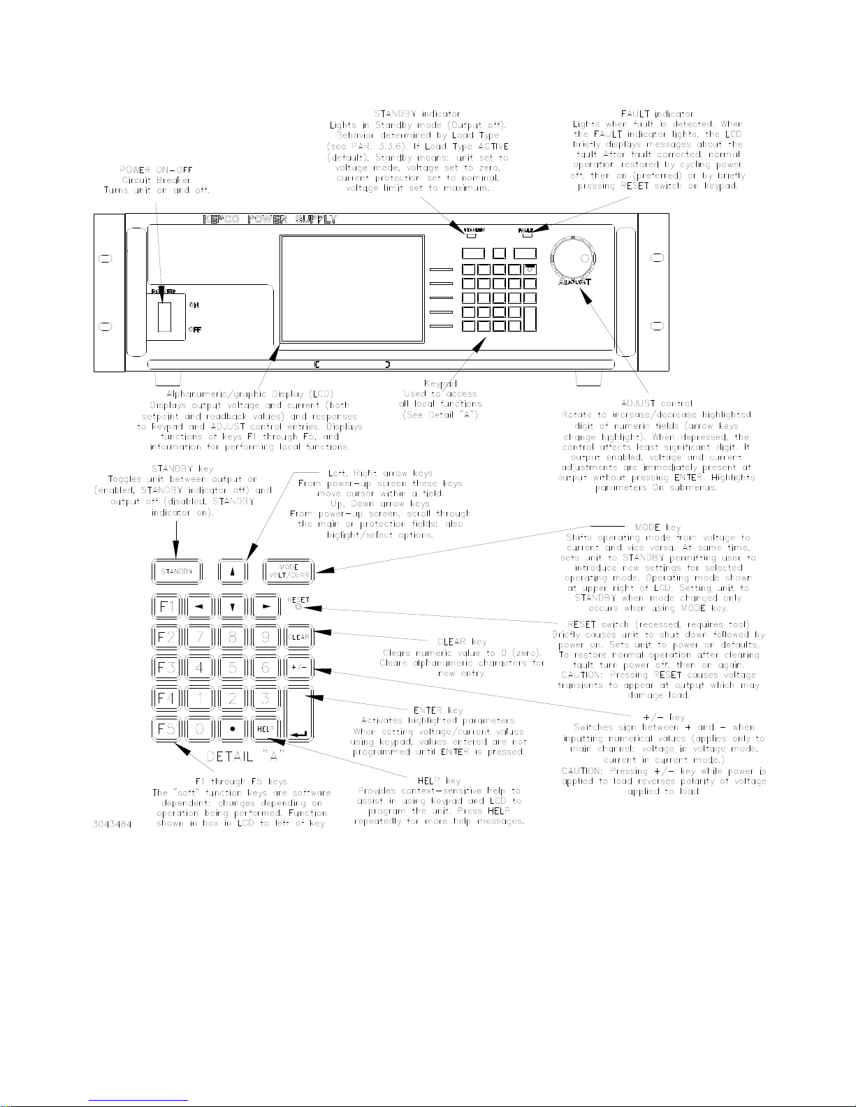
TURNING THE POWER SUPPLY ON.
CAUTION:
DO NOT repeatedly toggle the cir-
cuit breaker/switch as this may
damage the unit.
Set POWER ON/OFF circuit breaker/switch on front
panel to ON. If actuator does not lock when
released, wait a few seconds before trying again.
The circuit breaker is “trip-free” design; if overload
exists, contacts cannot be held closed by actuator.
• When the power supply is turned on, it per-
forms a brief self-test that includes testing the
three processors (analog, interface and dis-
play), then displays the power-up screen (see
Figure 5). If an error is detected, the FAULT
indicator will light, information about the error
will be briefly displayed on the LCD.
• If the unit powers up in REMOTE mode, press
!to set the unit to LOCAL mode.
• If the display is not viewable, press #twice.
The display will cycle through the range of
contrast settings. Press #again to lock in
the preferred contrast.
ACCESSING THE MENUS. From the power-up
screen, pressing the Function keys indicated on the
LCD opens the associated menu. The menu opened
may list submenus that may be opened either
directly by pressing the associated Function keys, or
by highlighting an item on the list and pressing the
View/Modify function key. Menus and submenus will
display a list of parameters, with the top one high-
lighted. The function key assignments can vary, but
generally offer the following choices:
•!allows the highlighted parameter to be
viewed or modified. After changing the param-
eter, the following choices are available: $-
SAVE or ENTER to save the change, %-
EXIT to abort the change and exit to the previ-
ous menu.
•@- RESTORE DEFAULT restores factory
defaults for the parameters displayed (except
for GPIB address). The factory defaults may
be saved as power-up defaults by pressing
$.
•#- The function varies, depending on the
menu. In most cases #is used to abort a
change without applying the modified setting.
From the power-up screen #is used to
adjust contrast. In the Revisions/TEST sub-
menu of the General Setup Menu, #is used
to execute a test.
•$- SAVE FOR POWER-UP Saves the con-
figuration shown as a power-up setting so the
changes will not be lost when the unit is
turned off.
•%- APPLY EXIT applies the current
(changed) setting without saving for power-up
and exits to the previous menu or to the
power-up screen, EXIT leaves the current
menu without saving or applying changes.
The menu structure is as follows (NOTE: BOLD =
Factory Default):
Power-up Screen (Power up menu)
•!- Save/Recall
• • Saved Setups: Recall one of 99 saved set-
ups.
• • • Saved Setup Details: Mode (voltage/
current/External), main channel refer-
ence (internal/external/external refer-
ence level) and setting, Protection Type
(internal/external/LesserLimit) and set-
ting(s), output status (on/off)
•@- Waveform
• • Saved Waveforms: Choose one of 16
saved waveforms.
• • • New Waveform Settings: Name (max.
10 characters), mode (voltage/current)
No. of cycles, +Protect, -Protect)
• • • • First segment: type (Square/ +ramp
/-ramp/triangle/sine/level),
Frequency, PtoP Amplitude, Offset
• • • Edit Waveform: Name, no. of cycles,
+protect, -protect, segment list, mode
• • • • Segment Details: Type ((Square/
+ramp/-ramp/triangle/sine/level/
slope/trigger), frequency or period,
amplitude, offset, start/stop angle
for sine and triangle, Repeat (initial/
repeat)
!

10 228-1692 REV 8 090418
KEPCO, INC. 131-38 SANFORD AVENUE FLUSHING, NY. 11355 U.S.A. TEL (718) 461-7000FAX (718) 767-1102
http://www.kepcopower.com email: hq@kepcopower.com
•#- Display
• • Display Settings:: Graphic Display
(meters/graphics, background (black/
white/monoblack/blue/green/lt.green/
lt.blue), Protect Entry (independent/bipo-
lar) Waveform Stop (outputOFF/User
Option), Key Press beep (On/Off/Error
only)
•$- Analog Remote Setup
• • Analog Remote Settings: Reference input
(internal/external/external reference
level), protect limit (Internal/External/Les-
serLimit), external mode (disable/enable)
•%- General Setup
• • Interface Settings:
• • • *RST set Output (on/off),
• • • GPIB Settings: Language (SCPI/CIIL),
GPIB address (default = 6), Device
clear (SCPI/MATE)
• • • Serial Settings: Baudrate (Off/9600/
19200/38400), Xon/Xoff (disable/
enable), prompt (disabled/echo/
enabled/enab+echo)
• • • LAN Settings: IP Address, IP MASK,
AUTO IP ON, DHCP ON, Name and
index (MDNS name)
• • Max/Min Settings: for voltage mode: +Volt-
age max, –Voltage min, ±CProtect max/
min; for current mode: +Current max,
–Current min, ±VProtect max/min
• • Load Type: Active/Resistive/Battery,
Remote On-off: (disabled/high is off/low is
off/high is on/low is on/LowPulseOff)
• • Standby Pin Operation: LowPulse, HighI-
sOn, LowIsOn, HighIsOff, LowIsOff, Dis-
abled
• • Revisions/Test: (Tests: display, keypad,
LAN, interface, serial, analog and output)
• • Calibration: Voltage, Current and External
and Controls calibration. Shows Firmware
versions for Display, Serial, GPIB, LAN
and analog.
• • Power-up Settings: Mode (Voltage/Cur-
rent/External), Main channel Reference
(Internal/External/ExtlRefLev), main set-
ting, Protection: Type (Internal/External/
LesserLimit), Voltage Limit (current mode),
Current Level (voltage mode), output ON/
OFF
• • Password
• • • Password Settings: Menu protection
(Interface/Max-Min/Load/Test/Calibra-
tion/Power-up/Keypad @ local/Key-
pad@power-up), Save Display Change
(Enable/Disable), Passwords (Unpro-
tected/Main/Admin1/Admin2)
• • Series/Parallel: Configuration (Standalone/
Parallel/Series/Master 2X2/Master 3X2);
for parallel or series: Unit Type (Stand-
alone/Master+1 to+4/Slave #1 to #4) and
Configuration: shows Series or Parallel).
FIGURE 5. POWER-UP SCREEN SHOWING GRAPHIC METERS
HOW TO MODIFY A PARAMETER.
First access the parameter by accessing the proper
menu as described above. To modify a parameter
listed in a menu or submenu, proceed as follows:
1. Highlight the parameter using the Yand Ukeys.
2. When the desired choice is highlighted, press !
to modify the active setting. The choices are dis-
played with the active setting highlighted. In the
case of numerals, the units digit is highlighted.
• To change a numeric setting, press the num-
ber keys, then press ENTER to program the
numbers entered. Use the CLEAR key to
clear numbers entered and start over. The
ADJUST control can also be used to incre-
ment or decrement the highlighted digit.

090418 228-1692 REV 8 11
KEPCO, INC. 131-38 SANFORD AVENUE FLUSHING, NY. 11355 U.S.A. TEL (718) 461-7000FAX (718) 767-1102
http://www.kepcopower.com email: hq@kepcopower.com
Pressing ADJUST while rotating adjusts the
least significant digit. If the output is on (unit
not in Standby) changes made using the
ADJUST control are immediately applied to
the output.
• For alphanumeric characters use multiple
presses of the number keys for letters or sym-
bols: 0(space), 1(+, –, /), 2(ABC), 3
(DEF), 4(GHI), 5(JKL), 6(MNO). 7
(PQRS), 8(TUV), 9(WXYZ). Use the T
key to highlight the next character. As an alter-
native, the Uor Ykeys or ADJUST control
will scroll through numbers, and letters and
symbols. Use the CLEAR key to clear the
entire alphanumeric field and start over
3. Press $to apply the change and return to the
menu (to change another parameter, repeat steps
1 and 2). To abort (return to the menu without
applying the change), press %.
NOTE:Press HELP key for more information,
press HELP again to see multiple
screens; press CLEAR key to exit the
help screen.
ADJUSTING LCD BRIGHTNESS, CON-
TRAST AND BACKGROUND From the power-
up screen, (Figure 5), press #twice to initiate con-
trast adjustment. The contrast gradually alternates
between light and dark. When the contrast is accept-
able, press #to apply the change and exit contrast
adjust. Use the Tand Rkeys for fine adjustment
of contrast. Contrast can also be adjusted from the
power-up screen by pressing #once, then press-
ing Tand Ras needed for fine adjustment.
To change the background, press #from the
power-up screen, Highlight Background, press !,
highlight Black or White, then $to save. Press $
exit and save for power-up or %to apply the
changes (without saving for power-up) and exit.
ENABLING/DISABLING AUDIBLE BEEPS
From the power-up screen, press #, then modify
the setting. Even though audible beeps are set to off,
the beeps will still sound upon power-up or detection
of a power supply fault.
SETTING VOLTAGE OR CURRENT MODE
The BOP uses two separate channels, one to set
output voltage or current and one to set the corre-
sponding protection limit. The main channel is deter-
mined by the MODE key (in local mode) which
alternately selects either Voltage mode or Current
mode or by SCPI command (in digital remote mode).
The protection channel is determined automatically
by the main channel selected. When Voltage mode
is selected, the current protection channel is active,
and when Current mode is selected, the Voltage pro-
tection channel is active.
PROGRAMMING VOLTAGE OR CURRENT
AND ASSOCIATED PROTECT LIMITS From
the power-up screen the settable voltage/current
parameters are displayed at the bottom of the LCD
above the HELP message. Use Yor Uto highlight
the main or protect channel.
1. To verify that the unit is configured for internal ref-
erences press $from the power-up screen and
verify that Reference Input and Protection Limit
are set to Internal, and External Mode is set to
Disable. If necessary to change a setting, use Y
or Uto highlight the parameter, and press !to
modify. Highlight the desired selection and press
$to save, then press $to save for power-up
or %to exit. If analog programming is desired,
refer to Operator’s Manual.
2. Verify that the load type has been configured
properly to ensure that the unit behaves as
expected when the output is off (see “Max/Min
Setting Menu” on page 13 6 for details).
3. Press MODE key to select the main channel
(VOLTAGE or CURRENT); the associated PRO-
TECT channel is automatically selected and dis-
played.
4. Set the output on or off as desired using the
STANDBY key. The output is off (disabled) when
the STANDBY indicator is lit, on (enabled) when
not lit.
5. Use Yor Uto highlight the main channel. There
are two ways to program the output in local mode.
These methods can be used either when the out-
put is disabled (STANDBY indicator lit) or
enabled. WARNING:
When the ADJUST control is
rotated, the active parameter is
immediately effective if the output
is enabled (on = STANDBY indica-
tor not lit). The voltage/current
applied to the load changes as the
ADJUST control is rotated.
• Use the ADJUST control to increase or
decrease the main channel setting (e.g., volt-

12 228-1692 REV 8 090418
KEPCO, INC. 131-38 SANFORD AVENUE FLUSHING, NY. 11355 U.S.A. TEL (718) 461-7000FAX (718) 767-1102
http://www.kepcopower.com email: hq@kepcopower.com
age when the unit is in voltage mode). Start
with the most significant digit of the desired
value, then use Tto highlight the next digit.
For fine adjustment press the ADJUST control
in while rotating the knob to modify the least
significant digit.
• Enter the desired value on the keypad using
the number keys. For example, to program the
BOP to 75.8V, press the following keys in
order 75.8 then press ENTER. For fine
adjustment use Y, and Uto modify the least
significant digit. To correct the entry before
activation press the CLEAR key to set the
value to zero and start over. When the desired
value is displayed, press ENTER. This causes
the new value to appear at the output and be
applied to the load if the output is enabled.
6. To program the corresponding Protect channel,
press Yor Uas necessary to highlight the Pro-
tect channel. Then set the value using either of
the two methods described above. If the Protect
Entry setting is set to Independent, separate
entries for the positive and negative protect chan-
nel are possible. Otherwise the value entered is
applied to both positive and negative protect
channels.
NOTE: The BOP can be configured to show
the protection limits as either a single
value that applies to both protection
channels or show individual settings
for positive and negative protection
limits. See Operator’s Manual for
details
SOFTWARE LIMITS. Software limits prevent
programming of the main channel or the Protect
channel beyond the software limit value. Refer to
Operator’s Manual for a full explanation of software
limits.
Changing Main Channel Software limit.
This procedure allows the user to determine the
maximum value of voltage or current that can be
programmed.
1. Press %from the power-up screen to enter the
General Setup menu, then highlight Max/Min Set-
tings.
2. Press !to enter the Max/Min Settings submenu
(Figure 6). (If a Password is required, see Opera-
tor’s Manual for instructions.)
3. Highlight the voltage or current max/min value
and press !to change it. Software limits are
absolute values (do not use minus sign for nega-
tive limits). Use number keys to change the set-
ting, then $to save.
4. When complete, press $to save for power-up,
#to abort, or %to apply the changes (without
saving for power-up) and exit.
5. Upon return to the power-up screen, the main
channel (voltage or current) is compared against
the main channel limits in effect. If the main chan-
nel exceeds the limit, it is set to zero.
6. Highlight the ±CPROTECT or ±VPROTECT max/
min value and press !to change it. Software
limits are absolute values (do not use minus sign
for negative limits). Use number keys to change
the setting. Press $to save, or %to abort.
7. When complete, press $to save for power-up,
or #to abort, or %to apply the changes (with-
out saving for power-up) and exit.
Upon return to the power-up screen, the new protec-
tion limit (voltage or current) is compared against the
protection limits in effect. If the new protection limit
setting is below the existing setting for the protection
limit, the protection channel (voltage or current) is
set to zero.
DETERMINING HOW THE UNIT RESPONDS
WHEN OUTPUT IS OFF (LOAD TYPE) The
BOP supports three Load Type selections (see Table
5) which determine how the power supply responds
when the output is off: ACTIVE, RESISTIVE and
BATTERY. The Load Type selection does not affect
the settings of the power supply for ON state; it only
affects the main internal reference level and the pro-
tection levels during the OFF state.
WARNING
For inductive loads, and especially
superconducting magnet type
loads, the inherent offset of the
BOP in the OFF state may generate
significant current in the circuit. A
properly rated switch in parallel
with a resistor must be connected
between the power supply and the
load. The switch must be open and
the BOP front panel LCD must read
0V, 0A before removing or installing
connections between BOP and
load.

090418 228-1692 REV 8 13
KEPCO, INC. 131-38 SANFORD AVENUE FLUSHING, NY. 11355 U.S.A. TEL (718) 461-7000FAX (718) 767-1102
http://www.kepcopower.com email: hq@kepcopower.com
Active. Active mode (default setting) is necessary
for the power supply to function properly and safely
with inductive loads and constant-current-type active
electronic loads. Active mode can also be used with
resistive loads. Table 5 indicates how the power sup-
ply responds to a command to go from Output ON to
OFF. When the output is disabled, the unit is set to
voltage mode, voltage is set to zero and both current
protect and voltage limit are set to maximum. When
the unit is enabled, the pre-existing settings for volt-
age, current protect and voltage limit are restored.
FIGURE 6. MAX/MIN SETTING MENU
WARNING
For both inductive loads and con-
stant-current-type active electronic
loads when the BOP output is set
to OFF, a path is provided for
absorbing either the energy accu-
mulated in the reactance of the load
during the ON state, or energy
delivered by an electronic load.
This prevents damage to the load
and power supply as well as pro-
viding safety for the user. However,
In addition to the built-in safety fea-
tures, constant-current-type active
electronic loads must be adjusted
to zero and the BOP front panel
LCD must read 0V, minimum cur-
rent, before handling the power
supply-to-load connections.
Resistive. This mode, as the name suggests, is
useful for resistive loads. Table 5 indicates how the
power supply responds to a command to go from
Output ON to OFF.
TABLE 5. POWER SUPPLY BEHAVIOR WHEN OUTPUT IS SET TO OFF
LOAD TYPE
SETTING If unit was in Voltage Mode when output OFF
command issued. If unit was in Current Mode when output OFF
command issued.
ACTIVE
• Unit remains in voltage mode.
• Voltage set to zero.
• Both ± Current Protect set to maximum.
• Both ± Voltage Limit remain at maximum.
• Unit set to voltage mode.
• Voltage set to zero.
• Both ± Current Protect remain at maximum.
• Both ± Voltage Limit set to maximum.
RESISTIVE
• Unit remains in voltage mode.
• Voltage set to zero.
• Both ± Current Protect set to minimum box values.
• Both ± Voltage Limit. remain at maximum.
• Unit remains in current mode.
• Current set to zero.
• Both ± Current Protect set to minimum box values.
• Both ± Voltage Limit set to maximum,
BATTERY
• Unit set to current mode.
• Current set to zero.
• Both ± Voltage Protect. remain at maximum.
• Both ± Current Limit set to maximum.
• Unit remains in current mode,
• Current set to zero.
• Both ± Voltage Protect set to maximum.
• Both ± Current Limit remain at maximum.
VOLTAGE
SOURCE
VOLTAGE CURRENT
0.0000 0.0000

14 228-1692 REV 8 090418
KEPCO, INC. 131-38 SANFORD AVENUE FLUSHING, NY. 11355 U.S.A. TEL (718) 461-7000FAX (718) 767-1102
http://www.kepcopower.com email: hq@kepcopower.com
WARNING
Accessing the BOP after the output
is disabled in BATTERY mode is
hazardous because (1) high current
arcing is possible and (2) either the
external battery voltage, or the volt-
age (±Voltage Protection max) on
the BOP output terminals may be
dangerous. Therefore, for battery
and constant-voltage-type active
electronic loads it is recommended
that two properly rated external
switches be installed for safety:
one in series with the battery, and
one across the BOP output. After
the unit is set to OFF, first open the
switch in series with the battery,
then close the switch across the
BOP output to ensure safety before
handling BOP connections. When
connecting the battery, the switch
across the output should be
opened after the connections are
complete and then the switch in
series with the battery should be
closed. If the constant-voltage-type
active electronic load is adjusted to
zero before handling the power
supply-to-load connections, only
the switch across the BOP output
is required.
Battery. This mode is necessary for the power sup-
ply to function properly and safely with either battery
or constant-voltage-type active electronic loads. This
mode prevents the battery from discharging during
the OFF state. When the output is disabled (set to
OFF), the BOP will go to current mode, current will
be set to zero, with voltage protect and current limit
set to maximum. In this way the battery will not be
discharged while the output is OFF. For constant-
voltage-type active electronic loads this mode stops
energy flow during the OFF state. Table 5 indicates
how the power supply responds to a command to go
from Output ON to OFF.
CONFIGURE LOAD TYPE. To configure, press
%from the power-up screen, then highlight Load
Type and press !to modify. (If a Password is
required, see Operator’s Manual for instructions.)
Highlight Active, Resistive or Battery (see explana-
tions and associated WARNINGS above) and press
$to save. Then press $to save for power-up,
#to abort, or %to apply the changes (without
saving for power-up) and exit. After configuring, the
new setting will be effective when the power supply
goes from output on to output off.
To restore factory default (Active), press %from the
power-up screen, highlight Load Type, press !,
then press @to restore default. Press $to save
for power-up or %to exit
ENABLING/DISABLING OUTPUT POWER.
The BOP output can be disabled (OFF) or enabled
(ON) by toggling the STANDBY key in local mode.
The behavior of the unit when disabled depends on
the Load Type setting (See “Max/Min Setting Menu”
on page 13. 6 and Table 5 for details).
IX — ADDITIONAL FEATURES.
The user is urged to refer to the Operator’s Manual
for full explanations all BOP 1KW features, includ-
ing:
• Passwords - three independent levels of
access
• Changing the Default Power up Settings
• Digital Remote Operation - using SCPI com-
mands via RS 232, GPIB or LAN ports; opera-
tion via web pages
• Analog Remote Operation - via Analog I/O
port
• Details about Protect Limits and Software-
controlled limits
• Storing/Recalling Power Supply Output Set-
tings
• Waveform Generation - Sine, Triangle,
±Ramp, Square and Level segments. Local
operation allows up to 16 waveforms, maxi-
mum 10 segments per waveform. Remote
operation allows 1 waveform, maximum of
126 segments, or using LIST commands.
• Operator Testing
• Calibration - via either local keypad or remote
SCPI commands
• Parallel/Series Configurations -increase cur-
rent capability, voltage capability, or both.

090418 228-1692 REV 8 15
KEPCO, INC. 131-38 SANFORD AVENUE FLUSHING, NY. 11355 U.S.A. TEL (718) 461-7000FAX (718) 767-1102
http://www.kepcopower.com email: hq@kepcopower.com
FIGURE 1. BOP 1KW OUTLINE DIMENSIONS (SHEET 1 OF 2)
20.000[508.00]
21.439[544.54]
22.800[579.11]
21.564[547.73]
22.000[558.79]
23.863[606.12]
18.235 [463.16]
18.985 [482.21]
1.470[37.34]
1.738[44.15]
5.218[132.54]
2.215[56.27]
OBROUND 0.25x0.453 (4 LOC.)
16.835 [427.60]
17.675 [448.93]
18.018 [457.64]
18.805 [477.63]

16 228-1692 REV 8 090418
KEPCO, INC. 131-38 SANFORD AVENUE FLUSHING, NY. 11355 U.S.A. TEL (718) 461-7000FAX (718) 767-1102
http://www.kepcopower.com email: hq@kepcopower.com
FIGURE 1. BOP 1KW OUTLINE DIMENSIONS (SHEET 2 OF 2)
SLIDES TRAVEL DISTANCE: 23.000 [584.2]
22.000 [558.79]
SEE NOTE 6.
REAR VIEW
REMOVE FEET FOR
RACK MOUNTING.
This manual suits for next models
8
Table of contents
Other KEPCO Power Supply manuals

KEPCO
KEPCO HSP Series User manual

KEPCO
KEPCO KLP SERIES User manual

KEPCO
KEPCO MSK 10-I0M User manual

KEPCO
KEPCO APH Series User manual

KEPCO
KEPCO BOP 10-100GL User manual

KEPCO
KEPCO FPD 50W-12V User manual

KEPCO
KEPCO BHK Series User manual

KEPCO
KEPCO HSF 5-20-1U User manual

KEPCO
KEPCO BOP-MG/ME 1KW User manual

KEPCO
KEPCO MSK 20-5M User manual

KEPCO
KEPCO 1KW-EL User manual

KEPCO
KEPCO PRR 48-22M User manual

KEPCO
KEPCO FAW 5-3K User manual

KEPCO
KEPCO KLP SERIES User manual

KEPCO
KEPCO RAX 3.3-10K User manual

KEPCO
KEPCO MAT Series User manual

KEPCO
KEPCO HSF 24-50A User manual

KEPCO
KEPCO ATE 1/4 RACK User manual

KEPCO
KEPCO KLP 600-4-1.2K User manual

KEPCO
KEPCO FPD 5-48W User manual