manuals.online logo
Brands
  1. Home
  2. •
  3. Brands
  4. •
  5. KEPCO
  6. •
  7. Power Supply
  8. •
  9. KEPCO HSF 5-10-1U User manual

KEPCO HSF 5-10-1U User manual

INSTRUCTION MANUAL
KEPCO
KEPCO, INC. " 131-38 SANFORD AVENUE " FLUSHING, NY. 11352 U.S.A. " TEL (718) 461-7000 " FAX (718) 767-1102
http://www.kepcopower.com " email: hq@kepcopower.com
An ISO 9001 Company.
©2006, KEPCO, INC 1
Data subject to change without notice 228-1453 REV 3
HSF-1U
50W
KEPCO SINGLE OUTPUT, 1U, 50 WATT
HOT SWAP PLUG-IN POWER SUPPLIES
I — INTRODUCTION
The Kepco HSF-1U 50 Watt Series hot swappable, high frequency switching, plug-in power supplies employ forward conversion
and are designed to operate in a fault tolerant power system with either a-c or d-c input. A thermistor soft-start circuit limits
start-up surge. A built-in forced current share circuit and OR-ing diodes allow configuration for hot-swap and parallel-redundant
N+1 operation.
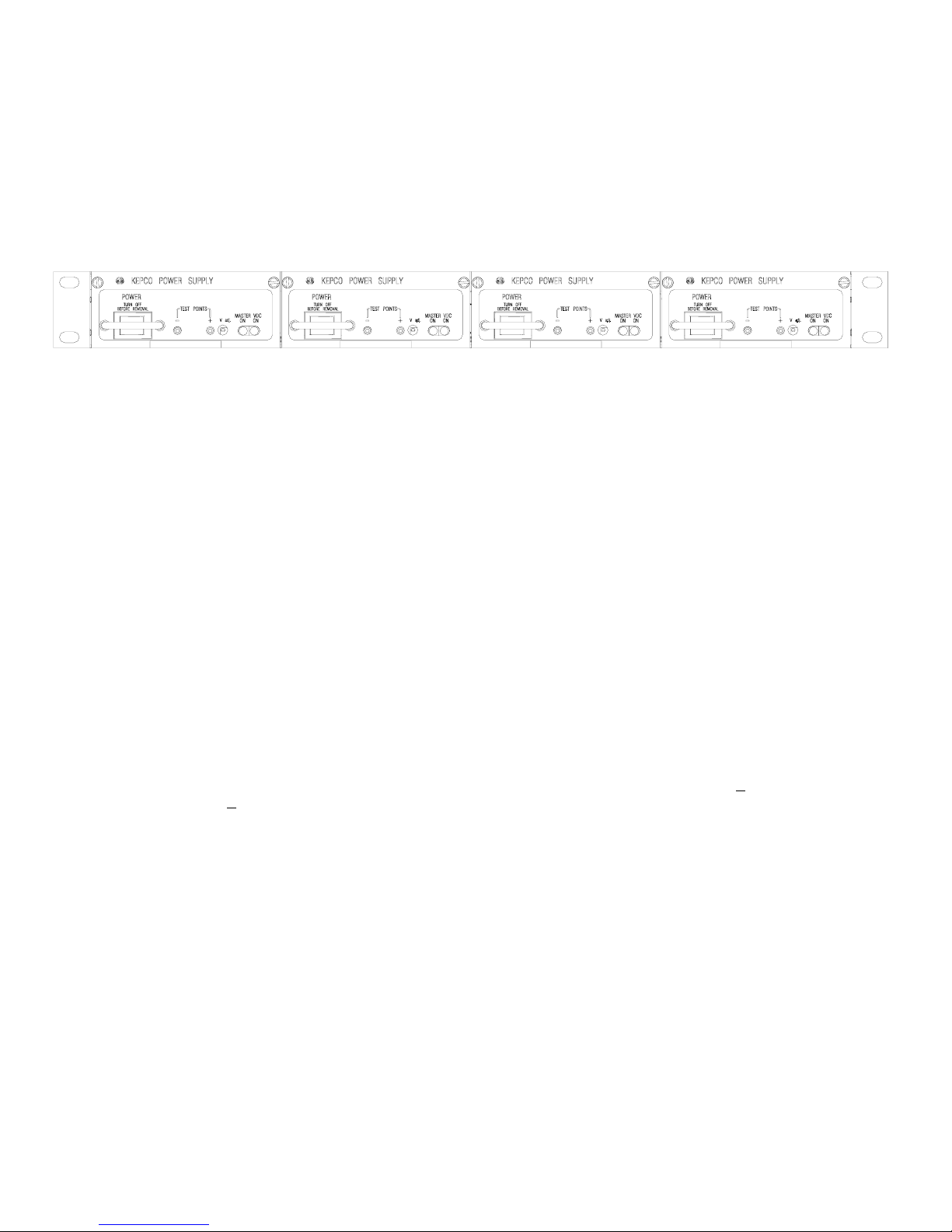
These power supplies are designed to be used with Kepco’s Series RA 19-1U rack adapters. The RA 19-1U rack adapter
accepts up to four 50 Watt or 100 Watt units (see Figure 1). All input/output connections are through a 24-pin connector that
plugs in to the rack adapter. All external connections are made through the rack adapter. Surface mount technology permits effi-
cient component layout for minimum mounting space.
Five models may be selected for outputs of 5, 12, 15, 24, or 48V (see Table 1).
When the input is cut off, the output is maintained for 15 milliseconds minimum. If the power supply shuts down due to an output
overvoltage condition, it is then necessary to wait 60 seconds minimum before turning the unit on again. EMI filtering is
designed to meet FCC Class B rating and VDE 0871 Class B rating. This page contains specifications for each model of the
HSF-1U 50 Watt Series. Environmental specifications for each model are the same.
II — FEATURES
FRONT PANEL ACCESS. The front panel provides a power ON/OFF switch controlling input power and a “VDC ON” light
which indicates when the unit is operating. NOTE: The ON/OFF switch must be set to OFF before removing unit from rack
adapter. The front panel “MASTER ON” LED lights when 1) the unit operates independently, or 2) the unit is used in parallel
redundant configurations while a) the output is less than 10% of nominal or b) the output is within 10% to 100% of nominal and
the unit is functioning as a master. In parallel redundant configurations, the module with the highest voltage functions as the
master. The other units are slaves, and track the output voltage of the master. Refer to Current Share Bus (CSB) on page 3 for
details. The front panel Vadj trimmer provides adjustment of the output voltage within the limits specified in Table 1; test points
connected to the +S and –S lines are available at the front panel for measuring the output.
FORCED CURRENT SHARE CIRCUIT. When units are configured for N+1 parallel redundant operation, it is desirable for cur-
rent to be divided equally among the paralleled supplies. When the CSB (Current Share Bus) lines of paralleled HSF-1U units are
connected together, the load current is forced to divide equally between all paralleled units. If one unit fails, the remaining units
will continue to supply the load, and the load current will be divided equally among the remaining operating units. The failed unit
is automatically isolated from the circuit by a built-in isolation diode. Refer to Current Share Bus (CSB) on page 3 for details.
TABLE 1. OUTPUT RATINGS AND SPECIFICATIONS, HSF-1U 50W SERIES
MODEL HSF 5-10-1U HSF 12-4.2-1U HSF 15-3.4-1U HSF 24-2.1-1U HSF 48-1-1U
OUTPUT VOLTS, d-c (NOMINAL) 5.0V 12.0V 15.0V 24.0V 48.0
ADJUSTMENT RANGE 4.5 - 5.5V 11.4 - 12.6V 13.5 - 16.5V 22.5 - 25.5V 45 - 51V
OUTPUT CURRENT (NOMINAL)(1)
(1) Derates same as Ouptut Power.
10.0A 4.2A 3.4A 2.1A 1.0A
OUTPUT POWER (NOMINAL)(2)
(2) See power derating curve, Figure 4.
50.0W 50.4W 51.0W 50.4W 48W
RIPPLE
AND
NOISE
(mV p-p)
0-40°C
10-100% LOAD
source (typ) 10 15 15 25 30
source (max) 20 30 30 30 60
switching (typ) 30 35 45 50 60
switching (max) 60 70 90 100 150
spike noise (d-c—50MHz) 120 190 220 310 350
OVERVOLTAGE SETTING 25°C, NOM. INPUT 6.5 - 7.5V 13.7 - 15.7V 17.0 - 19.0V 27.0 - 30.5V 53.5 - 60.0
OVERCURRENT SETTING 25°C, NOM. INPUT
Rectangular type characteristic 10.5 - 12.0A 4.4 - 5.1A 3.6 - 4.1A 2.2 - 2.6A 1.1 - 1.3A
KEPCO, INC. " 131-38 SANFORD AVENUE " FLUSHING, NY. 11352 U.S.A. " TEL (718) 461-7000 " FAX (718) 767-1102
http://www.kepcopower.com " email: hq@kepcopower.com
2228-1453 REV 3 082306
ALARM CIRCUIT. The HSF-1U includes an isolated internal relay offering normally closed and normally open contacts ref-
erenced to an isolated common. These contacts may be used to configure “close on failure” or “open on failure” alarm cir-
cuits. (Refer to the RA 19-1U Manual for alarm configurations for multiple HSF-1U power supplies.)
KEYING. Keying of the HSF-1U is established at the factory (see Figure 2). The output voltage determines which key pins
are installed. When the proper holes in the rack adapter are blocked by keying screws installed by the user, only a power
supply of the correct voltage can be inserted in the rack adapter slot. (Refer to the RA 19-1U Manual for rack adapter keying
instructions.)
FIGURE 1. HSF-1U 50 WATT POWER SUPPLIES (4) INSTALLED IN RA 19-1U RACK ADAPTER
III — SPECIFICATIONS
The following specifications apply to HSF-1U 50 Watt Series models (also refer to Table 1). Other models are also available;
consult your Kepco representative for their specifications.
INPUT:
Voltage: 120V a-c/240V a-c nominal; Range 95-264V a-c; 125-370V d-c. (polarity insensitive; consult factory)
Frequency: Nominal 50-60 Hz; Range 47-440Hz (at 440Hz leakage current exceeds UL/VDE safety spec.limit).
Current (nominal output at rated load): @120V a-c rms: 1.0A a-c typ., 1.2A a-c max;
@240V a-c rms: 0.5A a-c typ., 0.7A a-c max.
Initial Turn-on Surge: (one-half of first input cycle): @120V a-c rms, 45A max., @240V a-c rms, 90A max.
Brownout Voltage: 85V a-c, 110V d-c
Switching Frequency: 120KHz typical, nominal load
STABILIZATION:
Source Effect: Range 95-132V a-c or 190-264V a-c, 1.0% typ.; 2.0% max.
Load Effect: Range 10%-100% load, 1.0% typ.; 2.0% max.
Temperature Effect: Range 0oto 40oC, 1.0% typ.; 2.0% max.
Combined Effect: 2.0% typ.; 4.0% max. (includes source, load, and temperature effects).
Time Effect: 0.1% typ.; 0.5% max. (1/2 hr-8 hr at 25oC).
RECOVERY CHARACTERISTICS: A step load change from 50% to 100% produces less than +4% output excursion.
Recovery occurs to within +1% of the original setting in <2 ms (load change tr or tfequal to or greater than 50µsec).
START-UP TIME: 500 ms. maximum.
HOLDUP TIME: 20 ms. typ. (120V a-c), 15 ms. min (100V a-c).
DIELECTRIC STRENGTH:
Between input and output: 2KV a-c for one minute.
Between input and output with Y-capacitor removed: 3.75KV a-c for one minute.
Between input and case (ground): 2KV a-c for one minute.
INSULATION RESISTANCE: Between input and ground, output and ground, input and output;
100 Megohms min. (500V d-c).
LEAKAGE CURRENT
(UL method, 120V a-c): 0.5 mA maximum.
(VDE method, 240V a-c): 0.75 mA maximum.
SAFETY: Designed to meet UL 1950; CSA 22.2 No. 234 (M90) Level 3, EN 60950 Units are CE marked per the Low Volt-
age Directive (LVD), 73/23/EEC and 93/68/EEC. [The standards do not apply with DC input operation]
3042496
PS1 PS2 PS3 PS4
082306 228-1453 REV 3 3
KEPCO, INC. " 131-38 SANFORD AVENUE " FLUSHING, NY. 11352 U.S.A. " TEL (718) 461-7000 " FAX (718) 767-1102
http://www.kepcopower.com " email: hq@kepcopower.com
I/O CONNECTOR: The 24-pin I/O connector (Figure 2) is designed to mate with the corresponding connector in the
RA 19-1U Rack Adapter.
(+) SENSE, (–) SENSE: These lines are provided to compensate for voltage drops in the load connecting wires. The Sense
lines must be connected to their respective (+) and (–) output terminals, either at the load or at the rack adapter (see Rack
Adapter Manual). The connection ensures the most accurate error tracking. Error compensation in the connecting wires is up
to 0.25 Volts per lead for all models.
NOTE:
The Sense lines must be connected for the HSF-1U Power supply to work properly!
OUTPUT (+), OUTPUT (–): HSF-1U power supply d-c output.
CURRENT SHARE BUS (CSB): Connecting the CSB lines of HSF-1U power supplies operating in a parallel configuration
causes output current to be shared equally. (See Rack Adapter Manual for additional information on parallel configurations.).
For current sharing to work properly the outputs of all paralleled units must be within 250 mV (max) of each other and each unit
must be operating at between 10% to 100% of rated output. If current to the load goes below 10% for each unit in current
share mode, all MASTER ON lights may go on (see load effect specifications); this indicates that forced current share is no
longer working, units are simply in current share mode. (If forced current sharing at less than 10% nominal current per supply
is needed, contact Kepco application engineering.) Remote sensing is recommended. For master/slave operation to work
properly each unit should be adjusted to 40 mV (optimum) less than the next paralleled unit (unit 1 is adjusted to VOUT, unit 2
to VOUT – 40mV, and unit 3 to VOUT – 80mV, etc. If the master fails, the unit 2 will become the new master). The 40 mV dif-
ference can be reduced to a minimum of 25 mV as needed to parallel many units and still keep all units within 250 mV of each
other. Adjust the outputs using Vadj trimmer on front panel.
• Optimum difference among output voltages of paralleled units: 40mV
• Maximum difference among output voltages of paralleled units: 250 mV
• Minimum difference among output voltages of paralleled units: 25 mV
ALARM: The Alarm NC (normally closed) - Open on Failure and Alarm NO (normally open) - Close on Failure lines are relay
contacts referenced to Alarm Common. If the unit fails, the path between Alarm NC - Open on Failure and Alarm Common
opens, the path between Alarm NO - Close on Fail and Alarm Common is a short circuit. Figure 3 illustrates typical Close on
Fail and Open on Fail circuits to give a failure indication if any one of a number of power supplies fail.
INPUT POWER: Line (either a-c or d-c source power) , Neutral and Ground (chassis)
FIGURE 2. REAR CONNECTOR PIN ASSIGNMENTS FIGURE 3. TYPICAL ALARM CIRCUIT DIAGRAMS
4228-1453 REV 3 082306
KEPCO, INC. " 131-38 SANFORD AVENUE " FLUSHING, NY. 11352 U.S.A. " TEL (718) 461-7000 " FAX (718) 767-1102
http://www.kepcopower.com " email: hq@kepcopower.com
EMI: Designed to meet FCC Class B (100-120V a-c) and VDE 0871
Class B (220-240V a-c).
VIBRATION: (non-operating, one hour on each one of the three
axes):
5-10 Hz, 10 mm amplitude.
10-55 Hz, 2g acceleration.
SHOCK: (non-operating, one-half sinusoidal pulse, three shocks to
each axis):
Acceleration: 20g
Duration: 11ms +5ms
OPERATING TEMPERATURE: See Figure 4.
STORAGE TEMPERATURE: -40oC to +75oC.
OPERATING AND STORAGE RELATIVE HUMIDITY: up to 95%
(wet bulb temp. <35oC non-condensing).
FUSE: Quick acting 3.0A, 250V; (5.2 x 20mm), San-O P/N MT4 3A;
Kepco P/N 541-0110.
DIMENSIONS: See Figure 5.
WARRANTY: 5 years.
FIGURE 4. % OUTPUT POWER RATING VS.
AMBIENT TEMPERATURE
FIGURE 5. HSF-1U POWER SUPPLY OUTLINE DRAWING
13.050 [331.5]
1.732 [44.0] 0.228 [5.8]
1.088 [27.6]
0.282 [7.2]
0.503 [12.8]
0.190 [4.8]
0.191 [4.9]
0.125 [3.2]
0.507 [12.9]
0.140 [3.6]
0.140 [3.6]
0.250 [6.4]
0.507 [12.9]
0.156 [4.0]
0.391 [9.9]
4.295 [109.1]
1.732 [44.0]
0.140 [3.6]
0.140 [3.6]
0.250 [6.4]
0.125 [3.2]
0.133 [3.4]
3.960 [100.6]
0.076 [1.9]
0.066 [1.7]
0.780 [19.8]
0.437 [11.1]
1.108 [28.2]
0.010 [0.3]
1.131 [28.7]
0.471 [12.0]
0.690 [17.5]
0.303 [7.7]
0.750 [19.1]
3.755 [95.4]
4.275 [108.6]
1.474 [37.4]
0.591 [15.0]
1.125 [28.6]
3. MODULE IS KEYED AS SHOWN IN DETAIL
B) PCB 0.063" THK FR-4
1. MATERIAL:
A) BACKPLATE 0.064" THK. ALUM. 5052-H32
C) FRONT PANEL 0.090 THK. ALUM. 6061-T6
2. FINISH:
NOTES:
FRONT PANEL -KEPCO DUAL TONE GRAY
0.996 [25.3]
MAX MOUNTING
TORQUE:
2 IN.-LBS (0.23 N x m)
1.406 [35.7]
0.260 [6.6]
4. DIMENSIONS ARE IN INCHES, [DIMENSIONS IN BRACKETS
ARE IN MILLIMETERS].
5. TOLERANCES (UNLESS OTHERWISE SPECIFIED):
3 PLACES: ±0.005, 2 PLACES: ±0.01, FRACTIONS: ±1/64"
3
010248
12VOLTS
3.3VOLTS
5VOLTS
15VOLTS
24VOLTS
28VOLTS
KEYPINLOCATION
48VOLTS
=PINMISSING
=PINPRESENT

This manual suits for next models

9

Other KEPCO Power Supply manuals

KEPCO HSF-1UR Series User manual

KEPCO

KEPCO HSF-1UR Series User manual

KEPCO HSP Series User manual

KEPCO

KEPCO HSP Series User manual

KEPCO RTW 100W Series User manual

KEPCO

KEPCO RTW 100W Series User manual

KEPCO BOP 3/4 RACK User manual

KEPCO

KEPCO BOP 3/4 RACK User manual

KEPCO JQE 6-90 User manual

KEPCO

KEPCO JQE 6-90 User manual

KEPCO HSF 3.3-20PFC User manual

KEPCO

KEPCO HSF 3.3-20PFC User manual

KEPCO HSF-1UR 50W Series User manual

KEPCO

KEPCO HSF-1UR 50W Series User manual

KEPCO BOP 500DM User manual

KEPCO

KEPCO BOP 500DM User manual

KEPCO KLP SERIES User manual

KEPCO

KEPCO KLP SERIES User manual

KEPCO KLR SERIES Instruction Manual

KEPCO

KEPCO KLR SERIES Instruction Manual

KEPCO JBW 5-20K User manual

KEPCO

KEPCO JBW 5-20K User manual

KEPCO ATE 6-25 User manual

KEPCO

KEPCO ATE 6-25 User manual

KEPCO RAX 3.3-20K User manual

KEPCO

KEPCO RAX 3.3-20K User manual

KEPCO FPD 50W-24V User manual

KEPCO

KEPCO FPD 50W-24V User manual

KEPCO PAT 15-1 User manual

KEPCO

KEPCO PAT 15-1 User manual

KEPCO RKE 1500W SERIES User manual

KEPCO

KEPCO RKE 1500W SERIES User manual

KEPCO FAW 5-20K User manual

KEPCO

KEPCO FAW 5-20K User manual

KEPCO BOP 10-100MEL User manual

KEPCO

KEPCO BOP 10-100MEL User manual

KEPCO KLN Series User manual

KEPCO

KEPCO KLN Series User manual

KEPCO KLP 10-150-(2) User manual

KEPCO

KEPCO KLP 10-150-(2) User manual

KEPCO FPD 5-10-12 User manual

KEPCO

KEPCO FPD 5-10-12 User manual

KEPCO CC Series User manual

KEPCO

KEPCO CC Series User manual

KEPCO FAW 5-3K User manual

KEPCO

KEPCO FAW 5-3K User manual

KEPCO BOP 10-100GL User manual

KEPCO

KEPCO BOP 10-100GL User manual

Popular Power Supply manuals by other brands

Pulsar RUPS848T quick start guide

Pulsar

Pulsar RUPS848T quick start guide

CEA EA3000-3072Wh-1BK Product instruction manual

CEA

CEA EA3000-3072Wh-1BK Product instruction manual

Bosch FPP-RNAC-8A-4C Operation and installation guide

Bosch

Bosch FPP-RNAC-8A-4C Operation and installation guide

Aerocool Strike-X series datasheet

Aerocool

Aerocool Strike-X series datasheet

Intepro systems PSI 9040-170 3U operating guide

Intepro systems

Intepro systems PSI 9040-170 3U operating guide

Texas Instruments UCD3138 Technical reference manual

Texas Instruments

Texas Instruments UCD3138 Technical reference manual

Sonics FC instruction manual

Sonics

Sonics FC instruction manual

Omron E3G-L1 instruction sheet

Omron

Omron E3G-L1 instruction sheet

D-Link mydlink DSP-W215 user manual

D-Link

D-Link mydlink DSP-W215 user manual

First Choice PSEL-3000-2 troubleshooting guide

First Choice

First Choice PSEL-3000-2 troubleshooting guide

Door Controls PS17-TD2 installation instructions

Door Controls

Door Controls PS17-TD2 installation instructions

BE QUIET! PURE POWER L8-CM-430W user manual

BE QUIET!

BE QUIET! PURE POWER L8-CM-430W user manual

SATA AE5723 user manual

SATA

SATA AE5723 user manual

Keithley 2230G-30-3 quick start guide

Keithley

Keithley 2230G-30-3 quick start guide

GAMDIAS KRATOS M1-600B Quick installation guide

GAMDIAS

GAMDIAS KRATOS M1-600B Quick installation guide

SEW-Eurodrive MOVITRANS THM20C operating instructions

SEW-Eurodrive

SEW-Eurodrive MOVITRANS THM20C operating instructions

Aktakom APS-3103L user manual

Aktakom

Aktakom APS-3103L user manual

Schlage PS906 installation instructions

Schlage

Schlage PS906 installation instructions

manuals.online logo
manuals.online logoBrands
  • About & Mission
  • Contact us
  • Privacy Policy
  • Terms and Conditions

Copyright 2025 Manuals.Online. All Rights Reserved.