KEPCO HSP Series User manual

©2020, KEPCO, INC 1
Data subject to change without notice 228-1706 REV 2
KEPCO, INC. 131-38 SANFORD AVENUE FLUSHING, NY. 11355 U.S.A. TEL (718) 461-7000FAX (718) 767-1102
www.kepcopower.com email: hq@kepcopower.com
QUICK START GUIDE
KEPCO An ISO 9001 Company. HSP
1000W/1500W
SINGLE OUTPUT
PROGAMMABLE POWER SUPPLIES
I — INTRODUCTION
SCOPE OF MANUAL This Quick Start Guide covers
the installation and operation of the Kepco HSP Series of
voltage and current stabilized d-c power supplies. Full
specifications are listed in the applicable Operator’s Man-
ual that can be downloaded from the Kepco web site at
www.kepcopower.com/support/opmanls.htm/#hsp
FACTORY DEFAULTS This guide covers only units as
shipped from the factory with the three DIP switches set to
default configuration (see Figure 1). For other configura-
tions, refer to HSP Operator Manual.
DESCRIPTION The HSP power supply (Figure 1-1) is
basically a voltage and current stabilized d-c source with a
relatively sharp crossover between voltage and current
mode operation.
HSP power supplies are nominally rated at either 1000 or
1500 Watts of output power, and include active power fac-
tor correction (PFC). HSP 1000W power supplies are
designed to operate over the universal a-c power mains
voltage range of 90-277V (47-63Hz), with operation from
125-420V d-c also available. HSP 1500W products provide
full power over the a-c mains range of range of 180-277V
a-c, and 1000W output power from 90-132V a-c; contact
Kepco for information on operation over other source volt-
age ranges. Cooling is provided via an internal d-c fan.
HSP permits adjustment of both output voltage (VO) and
current limit (IMAX), either by internal (front panel pot) or
external (resistance or voltage) methods, selected via DIP
switches accessed through the top of the unit. Protection
against overvoltage, overcurrent and overtemperature fail-
ures is provided.
FIGURE 1. DIP SWITCH FACTORY DEFAULTS
The HSP power supply is specifically designed for use with
Kepco RA 60 or similar plug-in rack adapters as a hot
replaceable module in a redundant power system. Bench
top operation is also supported. Forced current sharing and
output blocking diodes enhance power system reliability.
Mechanical keying eliminates the risk of incorrect module
insertion. Tool-operated latches on the front panel guard
against casual removal of an operating module.
OPTIONS M models include a digital meter which dis-
plays either voltage or current as determined by a front
panel switch. Another switch allows display of either
actual HSP Output or the setpoint. B models are intended
for battery charging applications, and include a Float/
Equalize switch to preset two different voltage values
using two separate front panel adjustment pots.
TABLE 1. HSP SERIES MODELS
MODELS (1) 3.3V 5V 12V 15V 24V 28V 48V 125V
1000W HSP 3.3-230R HSP 5-200R HSP 12-84R HSP 15-66R HSP 24-42R HSP 28-36R HSP 48-21R HSP 125-8R (2)
1500W N/A N/A N/A N/A HSP 24-60R HSP 28-53R HSP 48-30R HSP 125-12R (2)
(1) Options include suffix M or B: M for meter; B for battery charger
(2) CE Marked, Not UL listed.

2228-1706 REV 2 071520
KEPCO, INC. 131-38 SANFORD AVENUE FLUSHING, NY. 11355 U.S.A. TEL (718) 461-7000FAX (718) 767-1102
www.kepcopower.com email: hq@kepcopower.com
II — INSTALLATION
KEYING. The units are keyed by voltage at the factory.
Refer to the Operator Manual for details.
MOUNTING THE POWER SUPPLY To insert in a
Kepco Rack Adapter, release the two cap head screw
retaining latches (see Figure 4) by loosening the cap-head
screw approximately 1/2 turn CCW (use 5/32" hex key)
and slide to open (up) position. Insert power supply in the
slot, then retighten the cap-head screws CW until snug.
DO NOT OVERTIGHTEN! To release, follow the same
procedure, except lift the latch to the top of the slot. Be
sure to move the latch completely up or down to ensure
full engagement/disengagement of the latching mecha-
nism. When HSP is not installed in rack adapter, secure
latch in open (up) position to prevent damage.
To use as a fixed, rack-mounted unit, see Operator man-
ual for details and accessories.
For all installations, provide adequate clearance around
air inlet and exhaust locations.
CONNECTIONS: Figure 2 shows proper connection
of one or more loads using either remote or local sensing.
If local or remote sensing is not configured, the unit
will not work properly. Observe polarities: negative
sensing wire must be connected to negative load wire,
and positive sensing wire to positive load wire. When used
with plug-in rack adapters, local sense wires must be con-
nected from the I/O connector to the ± studs of the rack
adapter.
Load connections to the HSP power supply are via bus
bars protruding from the rear panel (see Figure 2) or via
the rack adapter output studs.
Load cable or bus bar attachment should use either the
clearance hole of the HSP bus bar, using a 5/16" UNC
nut, bolt and lockwasher, or the rack adapter studs using
hardware supplied with the rack adapter. The proper hard-
ware is critical to maintaining intimate contact between the
load conductor and output bus bar.
FIGURE 2. LOAD CONNECTIONS
PRELIMINARY ELECTRICAL CHECK A simple
operational check after unpacking and before equipment
installation is advisable to ascertain whether the power
supply has suffered damage resulting from shipping.
1. Power supply will not operate unless remote
sense lines are properly connected to output ter-
minals! Connect remote sense terminals to output
bus bars using mating I/O Connector (Kepco P/N 142-
0422) or other means as shown in Figure 2.
2. Connect power supply to source power. Connection
can be made using either a North American linecord
set (Kepco P/N 118-0776) or using a custom linecord
terminated at one end with an IEC 320/C19 plug
(Kepco P/N 142-0381).
3. Connect a static load, R, across output terminals.
Load value is determined by HSP nominal output volt-
age and must be capable of handling 2% of power
supply output rating (20 watts minimum). R is calcu-
lated as approximately equal to output voltage2/20
(R = E2/P). For example, for the HSP 48-21, R = 482/
20 = 115.2; use load of 120 ohms, 20W.
4. CAUTION: DO NOT repeatedly toggle circuit
breaker as this may damage unit. Set Power ON/
OFF circuit breaker on front panel to ON. If actuator
REMOTE ERROR SENSING
LOCAL ERROR SENSING

KEPCO, INC. 131-38 SANFORD AVENUE FLUSHING, NY. 11355 U.S.A. TEL (718) 461-7000FAX (718) 767-1102
071520 228-1706 REV 2 3
does not lock when released, wait a few seconds
before trying again. The circuit breaker is “trip-free”
design; if overload exists, contacts cannot be held
closed by actuator. Verify that POWER indicator is lit,
and that all other front panel indicators are not lit.
5. Using a DVM, measure voltage across output bus
bars; this voltage is factory set to value shown in Table
1. If necessary, adjust output voltage using VOtrim pot
accessed through front panel.
6. Using DVM, measure voltage across test points VO
and COM; it should read 1/10 of output voltage mea-
sured in step 5 above, ±1%.
7. Using DVM, measure voltage across test points IMAX
and COM. This voltage is factory adjusted to 10.0V,
and corresponds to 100% of maximum current. Refer
to Operator manual for adjustment.
8. Verify that front panel indicators still appear as in step 4
above.
9. Disconnect sense lines with power supply still operat-
ing (remove mating I/O connector or open sense line
connected to pin 37. Verify that HSP output turns off,
and DC FAIL indicator is now lit along with POWER
indicator. (NOTE: At no load the output voltage will
drop slowly.) Turn circuit breaker off and wait until DC
FAIL indicator blinks. Reconnect sense lines, then turn
circuit breaker back on. Verify that output voltage
returns to value measured in step 5 above, and that
indicator LEDs appear as in step 4 above.
10. Turn off front panel circuit breaker and remove source
power connection.
III — OPERATION
CAUTION: DO NOT repeatedly toggle the circuit
breaker/switch as this may damage the unit. Set Power
ON/OFF circuit breaker to ON. When output voltage is
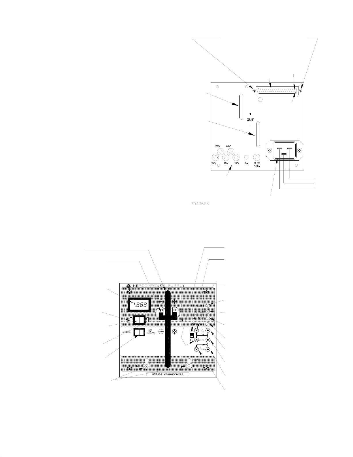
available, the green POWER LED is on (see Figure 4).
OUTPUT VOLTAGE PROGRAMMING Monitor out-
put voltage setpoint across VO and COM jacks while
adjusting VOpot on front panel. Voltage across VO and
COM represents 1/10 of the programmed output voltage.
As an example, VOof 4.63V corresponds to a programmed
output voltage of 46.3V ±1%. This relationship is constant,
regardless of the programming range selected.
Default programming resolution is set to high range: output
can be adjusted to 110% of nominal VOfor 3.3V through
28V models, 125% of nominal VOfor 48V models. For low
range (which offers increased resolution, while limiting out-
put to VO), or for external voltage programming using either
resistance or voltage refer to Operator manual.
For metered (M option) units, if the V/A switch is set to V,
actual output voltage is displayed on the meter in Volts.
While the ACTUAL/SETPOINTS switch is held in, the pro-
grammed output voltage setpoint is displayed in Volts.
CURRENT LIMIT PROGRAMMING Monitor current
limit setpoint across IMAX and COM jacks while adjusting
IMAX pot on front panel. Voltage across IMAX and COM rep-
resents the percentage of available power supply current
as a percentage of rated current, with 10V corresponding
to 100%. Available current is defined as the maximum cur-
rent limit available based on the programming range. This
voltage is always based on a 0-10V scale, regardless of
the range selected. For example, IMAX = 6.2V corresponds
to 62% of the maximum programmable current. For the low
programming range, this corresponds to 62% of the rated
module current, but for the high programming range the
number is 62% of 110%, or 68.2% of rated module current.
Current setpoint monitor accuracy is ±5%.
Minimum programmable current limit is 50-60% of nominal.
Default programming resolution is set to high range: cur-
rent limit can be adjusted to 110% of nominal IO. For low
range (which offers increased resolution, while limiting out-
put to IO), or for external programming using voltage
source refer to Operator manual.
For metered (M option) units, if the V/A switch is set to A,
actual output current is displayed on the meter in Amperes.
While the ACTUAL/SETPOINTS switch is held in, the pro-
grammed current limit is displayed in Amperes.
OVERVOLTAGE PROTECTION The overvoltage pro-
tection (OVP) circuitry latches the output regulator off if out-
put voltage rises above a predetermined level. To reset,
remove source power for a minimum of 30 seconds (refer
to Operator manual to enable remote reset). The trip level
is preset at the factory for 130% of the nominal output volt-
age. The trip point can be adjusted from 100% to 140% of
the nominal output (except Model HSP 48-21, which can
be adjusted from 100% to 160% of the nominal output). To
alter the preset OVP trip point, refer to the Operator man-
ual.
CURRENT LIMIT CHARACTERISTIC The factory
default setting is Continuous Limiting: When the output cur-
rent of the power supply reaches the programmed current
limit, the output regulator switches to current mode opera-
tion and maintains the output current by modulating output
voltage. Current mode is maintained indefinitely, and recov-

4228-1706 REV 2 071520
KEPCO, INC. 131-38 SANFORD AVENUE FLUSHING, NY. 11355 U.S.A. TEL (718) 461-7000FAX (718) 767-1102
www.kepcopower.com email: hq@kepcopower.com
ery to voltage regulation mode is automatic upon reduc-
tion of output current below the current limit point.
Current Limit can also be set to Undervoltage Lockout: if
current mode is maintained for more than 15 seconds, the
output is turned off, and source power must be recycled to
restart the unit. Refer to Operator manual for details.
OTHER FEATURES The following features of the HSP
power supplies are covered in detail in the Operator man-
ual:
• Parallel Operation, including load sharing require-
ments.
• Remote Inhibit, Remote Reset
• Remote Voltage and Current Limit adjustment
• Protection Circuits
• Status Flags and Indicators
• Load Monitor (Current)
• Current “Walk-In” for battery charging applications
• Load monitor
• Auxiliary supply
•Keying
• I/O Connector pin functions
• Options
FIGURE 3. HSP SERIES REAR PANEL CONNECTIONS
FIGURE 4. COMPONENT LOCATIONS
Output
Bus Bar
(+)
For Standalone operation, replace
connector mounting screws using
instructions and components supplied
in Standalone accessory KIT 219-0240
or KIT 219-0249.
Output
Bus Bar
(-)
Keyways and Plugs for module
keying (for use with Kepco
plug-in Rack Adapters)
Pin 1
Pin 20
I/O
Connector
Power Inlet
Connector
Line (Hot)
Ground
Neutral
EQ Adjust pot (B suffix only) Used to adjust
Equalize voltage while monitoring Vo and COM.
IMAX Adjust pot Used to adjust current limit from
front panel.
COM jack Provides return for Vo and IMAX
setpoint monitor jacks.
IMAX Setpoint monitor jack Used with COM jack to
monitor current limit setpoint.
Vo Setpoint monitor jack Used with COM jack to
monitor voltage setpoint.
OVERTEMP indicator Lights amber to indicate
overtemperature detected.
POWER Indicator Lights green when unit
is operating. Off when fault detected.
ACTUAL/SETPOINTS momentary switch
(M Suffix only) Meter normally shows actual
output voltage or current. Meter shows
setpoints while switch is pressed.
Power ON/OFF circuit breaker Applies
power to the unit. CAUTION: Power must
be OFF before unit is removed from the
rack adapter.
Voltage/Current Meter (M Suffix only)
Monitors output voltage or current per
Meter Mode switch. Remote sensing required
for voltmeter to display voltage at the load.
DC FAIL Indicator Normally off. Lights red to
indicate failure.
FAN FAIL indicator Lights red to indicate fan
failure.
Insertion/Extraction Handle
Vo Adjust pot Used to adjust output voltage
setpoint. Used to adjust Float voltage on
B suffix models.
FL/EQ Select switch (B suffix only) Allows
either Float or Equalize voltage to be monitored
across Vo and COM jacks. CAUTION: Adjust
only the pot selected by FL/EQ switch.
Retaining Latches (2) Prevents inadvertent
removal of unit from rack adapter.
3043522
Meter Mode switch (M Suffix only)
Set to V to show output voltage on meter,
set to A to show output current.
V (Voltage) indicator (M Suffix only)
Lights green when meter shows Volts.
A (Amperes) indicator (M Suffix only)
Lights amber when meter shows Amperes.
Other manuals for HSP Series
1
This manual suits for next models
12
Other KEPCO Power Supply manuals

KEPCO
KEPCO BOP-1KW User manual

KEPCO
KEPCO KFD 6-25-60W User manual

KEPCO
KEPCO FPD 50W-24V User manual

KEPCO
KEPCO HSP-A Series User manual

KEPCO
KEPCO HSF 12-53 User manual

KEPCO
KEPCO KLP SERIES User manual

KEPCO
KEPCO HSF A User manual

KEPCO
KEPCO MAT FULL RACK 6V User manual

KEPCO
KEPCO BOP 400W User manual

KEPCO
KEPCO PAT 72-0. User manual

KEPCO
KEPCO BOP 6-125MG/ME User manual

KEPCO
KEPCO HSF-A User manual

KEPCO
KEPCO 3.3-70K User manual

KEPCO
KEPCO HSF 5-60 User manual

KEPCO
KEPCO ATE 6-25 User manual

KEPCO
KEPCO 1KW-EL User manual

KEPCO
KEPCO BOP 5-20DL User manual

KEPCO
KEPCO FAW 5-3K User manual

KEPCO
KEPCO FDP 5-20-48 User manual

KEPCO
KEPCO APH Series User manual