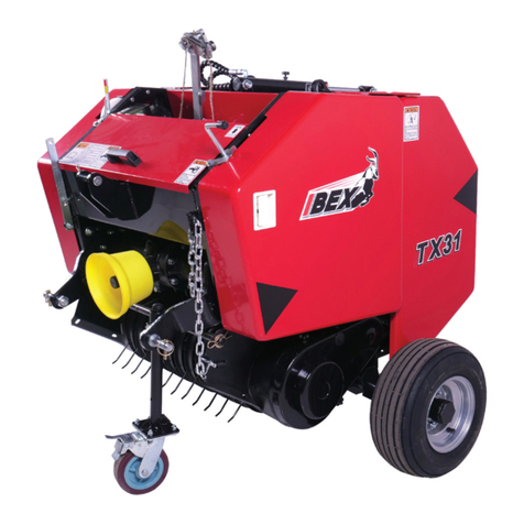
IBEX TX51 2 Wheel Rake User manual

WHEEL RAKE
INSTRUCTION MANUAL


SPECIFICATIONS
Model
TX51 2 Wheel
Rake
TS130 4
Wheel V-Rake
TM150 4
Wheel Rake
Approximate Weight (Lbs.) 188 260 400
Number of Wheels 2 4 4
Number of Tines per Wheel 40 40 40
Wheel Diameter 55” 55” 55”
Tooth Diameter 7mm 7mm 7mm
Working Width 4’3” 10’10” 9’6”
Operating Speed Up to 14 MPH Up to 14 MPH Up to 14 MPH
SAFETY INSTRUCTIONS
When ordering parts, please specify the part
number and the name of the part as shown in
the parts section. Please give the serial num-
ber of the machine in all correspondence.
Record the serial number and purchase date
here for future reference.
Serial No:
Model:
Purchase Date:
Read through this manual completely,
watching especially for safety symbols
which alert you to possible hazards in as-
sembly and operation. The word “NOTE” will
alert you to special informa
tion such as
specification, techniques, reference infor-
mation and other supplementary infor-
mation. The word “IMPORTANT” is used to
point out a no
te which is of an immediate
and urgent nature
It is the user’s responsibility to read the oper-
ator’s manual and comply with all instructions
pertaining to operation and maintenance. It is
also the user’s responsibility to inspect the
machine at regular intervals and repair or re-
place worn or damaged parts when continued
use would cause damage or excessive wear
to other parts. Delivery of the machine to the
manufacturer’s dealer for repairs under the
warranty is also the user’s responsibility.
Always drive the tractor at safe speeds, espe-
cially over rough ground and sloping ground
and when making a turn.
Never attempt to clean, adjust or lubricate the
machine while the machine is in motion.
REMEMBER: A CAREFUL OPERATOR IS THE
BEST INSURANCE AGAINST AN ACCIDENT.
CAUTION: ALWAYS FOLLOW
ALL STATE, FEDERAL AND
LOCAL LAWS WHEN
TRASPORTING. MAKE SURE
SMV SYMBOL AND LIGHTS
ARE IN PLACE BEFORE
TRANSPORTING WHERE
REQUIRED DO NOT EXCEED 15
MPH DURING TRANPORTING.

CAUTION: This machine should
never be operated by anyone who
is not
familiar with the product
and has note read the instruction
manual. Do not operate the rake
where people or animals are in the
immediate area.
IMPORTANT: When this machine is traded or
sold, make sure this manual accompanies the
machine so future operators will have complete
operating instructions and safety warnings avail-
able to them.
NOTE: All reference number used in the assem-
bly instructions correspond to the item numbers
used in the parts breakdown section of this man-
ual. When left or right-hand position are men-
tioned, they refer to the position as viewed from
the rear of the machine while facing the tractor.
ASSEMBLY
Note: The assembly steps below are for the in-
line four (4) wheel model. Assembly of the two
(2) wheel and four (4) wheel v-rake models is
similar. The wheel arms and wheels attach in the
same way. Note the wheel orientation in the pic-
ture on p.4.
1. Install the Pivot Support (8) on the 3-Point
Base (1). Insert the 3-Point Cap (17) and se-
cure in place with a cap screw and locknut
through the cap and base. Lock the support
plate in position on the 3-pont base with a 3-
Point Pin (10) secured with a Hairpin Cotter
(9). See illustration 1.
2. Install the Stand (3) on the 3-pont linkage and
secure with a spring clip. See Illustration 2.
3. With the assembly laying on the ground so the
sector plate’s lower socket
is facing up, insert
the Floating Arm (26) into the socket and secure
with a Sector Support Pin (15), two flat washers
(32) and two Cotter Pins (14). Lock the floating
arm in position by installing the Lock Plate (27)
on the bottom
of the arm and secure with a
Hairpin Cotter (4). See Illustration 2.
4.
Install the two Extension Springs (21) in the
plate near the top of the pivot support and then
connect the oth
er ends of the springs to the
Lower Spring Mount (23). Secure the lower
spring mount to the floating arm using a cap
screw and nut. Use the center hole for the time
being. After final assembly, move
the lower
mount necessary to allow the rake to “float” in
operation. See Illustration 2.
5. Insert the Main Frame (33) into the Floating Arm
(26). Lock the arm in place by installing the
Lever Plate (16) on the floating arm and secure
with a pin and retaining rings. Insert a Snapper
Safety Pin (19) to lock the stop plate and secure
with a hairpin cotter. See Illustration 3.
6. Install the Wheel Arms (34) in the main frame
and secure the Lever Plates (16) with a pin and
retaining rings and a snapper safety pin. See Il-
lustration 4.
CAUTION: Make sure the machine is
supported as the main frame and
wheel arms are installed to prevent
the machine from falling.

Illustration 3
Illustration 4
7. Using on overhead hoist of forklift, carefully tip
the assembly over and support the assembly
in the approximate position it will be in when
installed on the tractor and high enough off the
ground to install the wheels. Install the wheels
on the hubs using the cap screws and nuts.
Use medium strength thread locker to secure
nuts to bolts. The position of the teeth is de-
termined by the direction of operation (See Il-
lustration 5 Below as well as the image on p.
4).
Left Rake Right Rake
Rake wheels as viewed
from the rear
Illustration 5
When assembled, the rakes should be configured
as shown in Illustration 6 below.
Illustration 6

STANDARD WHEEL ORIENTATION (4 WHEEL, RIGHT HAND SHOWN)

Illustration 6 (Continued)
CONNECTING THE RAKE TO THE TRACTOR
With the rake supported by the wheel tines
and the stand, back the tractor to the rake and
connect the tractor to the 3-pont linkage. After
connecting to the tractor, r
aise the machine
and remove the stand from the 3-point linkage.
Raise the rake using the tractor hydraulics un-
til the tines
are off of the ground. Slide the
Lock Plate (27) to the rear “B” to allow the
rake to “float” during operation (See Illustration
7). This will allow the rake to adapt to irregular
ground and reduce wheel damage.
IMPORTANT: The lock plate must be in the
forward position “A” whenever the rake is be-
ing transported or not in operation.
Illustration 7
OPERATION
The 3-Point Pin (10) is used to adjust the op-
erating position of the rake. Position “A” (See
Illustration 8) is used for raking position to the
right. Position “B” is used for raking to the left.
Illustration 8
By using adjustment holes 1 through 6 in the
right or left position minor adjustments can be
made when raking, spreading and turning the
crop. When transporting the rake, the stop pin
must be installed in position 7 (See Illustration
9).
Illustration 9

WORKING POSITIONS
Pull the pin in the pivot support and turn the
main frame to the right and rotate the arms so
the wheels are positioned as shown below (See
Illustration 10). During operation, the wide slots
in the frame and arm flanges allow the arms to
oscillate slightly to prevent damage to tines by
rough ground surfaces. The narrow slots used in
the transport positioning hold the arms in a rigid
position.
RIGH-HAND RAKE OPERATING POSITIONS
TURNING SPREADING RAKING
Rotate the main frame to the
right and the arms to the left.
Lock in place with pins.
Rotate the main frame and arms
to the left. Lock in place with
pins.
Rotate the main frame and arms
to the left. Lock in place with
pins.
Illustration 10
TRANSPORTING
To reduce the width of the rake for transporting
between fields, perform the following steps:
1. Raise the rake to the highest position.
2. Unlock the main frame at the Floating Arm
(26) and rotate the frame so the forward
wheel is at the top. Rotate the arms to the
horizontal position. Center the rake behind
the tractor.
3. Move the floating arm stop to the forward
position to lock the frame in position during
transporting.
Illustration 11

TROUBLESHOOTING
PROBLEM PROBABLE CAUSE SOLUTION
Hay carrying over on the
wheel.
1.
Wheel tines are new; paint is grip-
ping material.
1.
Operate rake on a rough surface,
such as gravel, for a short dis-
tance.
2.
Mud collected on tine ends.
2.
Dew on hay, wait until dry.
Do not run in soft, wet ground.
Tine breakage.
1.
Backing with tines in contact with
ground.
1.
Avoid backing with tines on
ground.
2. Too much weight on wheels. 2. Raise the 3-point hitch slightly.
3.
Corrosion in storage.
3.
Coat teeth with grease or oil dur-
ing storage.
Rake missing hay.
1. Wheels running too flat. 1. Adjust angle at sector plate.
2.
Wheels not pitched back enough.
2.
Pitch wheels back by adjusting 3-
point top link.
3.
Teeth missing or worn.
3.
Replace teeth. It is best to replace
all teeth at same time to maintain
uniform tine height.
Rake wheels bounce exces-
sively. 1.
Wheels have too little ground
weight. 1. Lower 3-point hitch.
Bent tines.
1. Backing with wheels down. 1. Avoid doing so.
2. Excessive speed on rough terrain 2. Reduce speed.
3.
Narrow or deep ditches or furrows,
rocky ground.
3.
Avoid or cross slowly.
4. Too much weight on wheels. 4. Raise 3-point slightly.
MAINTENANCE
This Wheel Rake requires no tools for operation and no lubrication is required except for occa-
sional repacking of the hub bearings on the wheels with grease. A light coating of grease ap-
plied periodically to the frame and arm pivots and flanges will allow smoother operation and re-
tard rusting which will hinder operation.
This manual suits for next models
2
Table of contents
Other IBEX Farm Equipment manuals
Popular Farm Equipment manuals by other brands

AGROFROST
AGROFROST Frostbuster F501 Operating & maintenance instructions

GREAT PLAINS
GREAT PLAINS Terra Max HT1110-6.0M Operator's manual

Worldwide Construction And Forestry Division
Worldwide Construction And Forestry Division 410J Technical manual

paladin
paladin FFC LAF5647 Operator and parts manual

Tatu Marchesan
Tatu Marchesan GCRO 7010 instruction manual

Rabe
Rabe Raven Avant Series Operating instruction