K-Line SPEEDTILLER 2900 Series User manual

OPERATING MANUAL
SPEEDTILLER®
2900 3 Point Linkage
Folding Wing, Non-Folding Wing
Universal Model
Serial No.
2918U- Shown
2918U

K-Line Ag ©
__________________________________________________

K-Line Ag ©
__________________________________________________
Table of Contents
K-Line Ag has produced this manual as a guide for the operation of your machine.
While every care and precaution has been taken in compiling this booklet, K-Line Ag carries no responsibility for
errors and omissions.
This production is made available as is, without warranty of any kind expressed or implied.
K-Line Ag assumes no responsibility for damages resulting from the use of information contained herein.
This booklet is compiled to comply with the present state of the machine at the time of publication, and K-
Line Ag reserves the right to improve and revise their products at any time
Introduction
1
First Start-up
19
Identifying the machine
2
What do you need your Speedtiller®to do?
19
Tractor requirements
2
Problem Solving
20
Definitions used in this manual
2
Daily Maintenance
21
Safety Alert
3
To convert from Trailing mode to 3PL mode
22
Safety Alert Symbol
3
To convert from 3PL mode to Trailing mode
22
Signal words
3
Performing maintenance
23
Your Safety & the Safety of other Persons is
Important
4
Priming Hydraulic System
24
Safety sign locations
5
Lubrication of rear Roller bearings
24
Safety Decals
6
Tire Safety and Pressures
24
Safety sign care
8
Attaching jump arm to machine
25
To order Safety Decals
8
Standard Rear Roller bearing assembly
26
How to Install Safety Decals
8
Exploded view of disc arm bearing
27
Safe Operation
8
Exploded view of side coulter
28
Hitching and Un-hitching
9
Magna-Lite Wiring Harness Schematic
29
Hydraulic Hose hook-up
10
Bolt torque table Imperial
30
Electrical connection hook-up
10
Bolt torque table metric
31
Wheel transport safety locks
11
Speedtiller®Specifications
32
Transporting/Roading
11
Risk Management
34
Power lines can arc and electrocute
12
K-Line Agriculture risk assessment
36
Hydraulic System Failure
13
Warranty
37
Machine Operation
14
Warranty registration form
39
Setting & Adjustments
14
Warranty Request form
41
Speed Range
14
Depth control
15
Fore and Aft level (tilt) & correct tracking
15
Front disc gang lateral positioning sideways
adjustment
17
Side coulter adjustment
18

K-Line Ag ©
__________________________________________________

K-Line Ag ©
__________________________________________________
Page | 1
Dear Customer
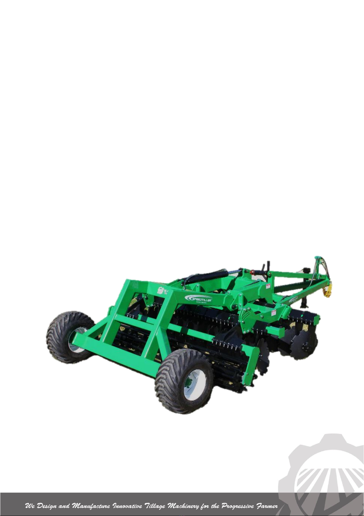
Thank you for purchasing a 2900 Three Point Linkage Universal Speedtiller®. We would
like to assure you that you have made a good choice, and will be able to rely on this
high quality piece of equipment. We ask you to follow the user’s instructions closely, as
this will ensure that you experience the benefits of using the machine without
experiencing the unnecessary down time caused by misuse.
When you receive the machine, make sure that it has not been damaged during
transportation and that no parts are missing. Contact your dealer immediately if any
parts are missing. Ensure that all components are correctly adjusted.
The return of the Warranty Registration Form (Page 41) will enable a prompt and
efficient identification of your 2900 Three Point Linkage Universal Speedtiller®and
attention to any concern you may have.
Before operating PLEASE TAKE THE TIME TO LEARN the process of operation. Do
not take the unit for granted; ease into becoming familiar with your new equipment. The
operator should be a responsible adult familiar with farm machinery and trained for this
purpose. Do NOT allow persons to operate or assemble the unit until they have read
this manual and understand how to use this machine, and observe the safety
precautions.
Never exceed the limits of this machine. If its ability to do a job, or to do so safely, is in
question - DO NOT TRY IT.
DO NOT attempt to operate this equipment under the influence of drugs or alcohol.
Remember - Your best assurance against accidents is a careful and responsible
operator.
If you have any questions not answered in this manual or require additional copies or
the manual is damaged, please contact your dealer or be free to Phone us on our Free
call Number: USA - 1800 445 6882 AUS - 1800 194 131
The team here at K-Line Agriculture trust you enjoy a good season and prove the
benefits of owning and operating a quality machine that is built to perform.
Signed:
James Larsen
General Manager

K-Line Ag ©
__________________________________________________
Page | 2
IDENTIFYING THE MACHINE FOR REQUESTING SPARE PARTS
The machine is identified by the serial number on the metal plate on the machine. When
requesting spare parts or maintenance service, please indicate the model and number
of your equipment to ensure prompt and efficient attention.
AVAILABILITY OF GENUINE PARTS
K-Line spare parts and accessories have been specifically designed and developed for
the machines produced. We would call your attention to the fact that non-genuine parts
and accessories are not recommended by K-Line. The use of such replacement parts
frees K-Line from all liability and makes the warranty void. The installation and/or use of
non-genuine parts may, because of technical characteristics of construction, may modify
or influence the performance of the machine negatively.
AFTER DELIVERY
When you receive the machine, make sure that it has not been damaged during
transportation and that no parts are missing. Only by giving us immediate advice can the
necessary replacement parts be obtained. Ensure that all components are correctly
adjusted.
TRACTOR REQUIREMENTS
10-14 Horsepower x width of machine in feet
25-35 kilowatt x meter width of machine in meters
Check the tractor manufacturer specifications for weight and suitability of rear
mounted implements
1 x double spool
Hydraulic operating pressure 2800 PSI / 19000 KPA
DEFINITIONS USED IN THIS MANUAL
Left
Right
Hand
Side
Hand
Side

K-Line Ag ©
___________________________________________________________________
Page | 3
Safety Alert!!
Safety…You Can Live With It
SAFETY ALERT SYMBOL
When you see this symbol, you must be
alert to the possibility of injury or death.
SIGNAL WORDS
The use of signal words DANGER, WARNING and CAUTION relating to the safety
messages. The appropriate Signal Word is selected using the following guidelines.
DANGER: indicates an imminently
hazardous situation that, if not avoided,
WILL result in serious injury or death if
proper safety measures are not taken.
WARNING: Indicates a potentially
hazardous situation that, if not avoided
COULD result in serious injury or death if
proper safety measures are not taken.
CAUTION: Indicates a potentially
hazardous situation that, if not avoided
MAY result in serious injury or death if
proper safety measures are not taken.
IT IS THE RESPONSIBILITY OF THE USER TO MAINTAIN IN AS NEW CONDITION
ALL SAFETY SIGNS AND DEVICES USED ON THIS MACHINE. FAILURE TO
OBSERVE THE INSTRUCTIONS OF THIS BOOKLET COULD RESULT IN SERIOUS
INJURY OR DEATH.
Be Familiar with Safety Decals
Read and thoroughly understand all
the ‘Safety Decals” on (Pages 8 &
9) and throughout this manual.
Safety Alert

K-Line Ag ©
___________________________________________________________________
Page | 4
Your safety and the safety of
other persons is important!
BE PREPARED
Wear suitable clothing –loose clothing is dangerous
Use hearing protection –loud noises can cause deafness
Use gloves and eye protection –high pressure fluids are dangerous. Release
pressure from hydraulic lines before disconnecting
BE SAFE
Attach safety chains to towing unit
Only operate machine from tractor seat
No riders on machine
Keep body well clear –machine components can suddenly move or fall
Shut down tractor while making adjustments
Do not exceed speed limit 20 mph (32 km/h) –UNBRAKED MACHINE
For road travel conform with All federal, state and local authority requirements
BE AWARE
Pay full attention to your task –distractions while operating machinery are
extremely dangerous
Check for overhead power lines
Keep clear of escaping high pressure fluid which can penetrate the eyes and skin
BE SEEN
Use approved safety signs and lighting
Safety Alert

K-Line Ag ©
___________________________________________________________________
Page | 5
Safety Sign Locations
Familiarise yourself with the safety sign location and type of warning for safety
awareness!
IMPORTANT
If safety signs have been damaged, removed, become illegible or parts replaced without
decals, new decals must be applied. New decals are available from your authorised
dealer or direct from factory.
Figure 1
Safety Alert
H
A
J
K
C
G

K-Line Ag ©
___________________________________________________________________
Page | 6
SAFETY DECALS
TO REORDER FREE CALL AUS- 1800 194 131
USA- 1800 556 6882
(Re-order according to part numbers shown below)
*Affixed on every wheel
A.
B.
C.
E.
G.
D.
F.
Safety Alert

K-Line Ag ©
___________________________________________________________________
Page | 7
Decal
Part Number
A.
9WD-W022
B.
9WD-C023
C.
9WD-W05
D.
9WD-D04
E.
9WD-D01V
F.
9WD-D01H
G.
9WD-W021
H.
9WD-C04
I.
9WD-I01
J.
9WDW-T5
K.
9WDD-T3
L.
9WD-W024
M.
9WD-W10
N.
9WD-W01
H.
….
J.
I.
J
K.
J
L.
J
M.
J
Safety Alert
N.

K-Line Ag ©
___________________________________________________________________
Page | 8
Safety Sign Care
Keep safety signs clean and legible at all times
Replace safety signs that are missing or have become illegible
Replaced parts that displayed a safety sign should also display the current sign.
To order Safety Decals contact:
USA: K-Line Agriculture
PO Box 567
700 Division Avenue S
Cavalier ND 58220
Email: [email protected]
Freecall: 1800 445 6882
How to Install Safety Signs:
Be sure that the installation area is clean and dry.
Decide on the exact position before you remove the backing paper.
Remove the smallest portion of the split backing paper.
Align the decal over the specified area and carefully press the small portion with the
exposed sticky backing in place.
Slowly peel back the remaining paper and carefully smooth the remaining portion of
the decal in place.
Safe Operation In field and
Transport/Roading
Read and understand your manual
Take time to familiarize yourself with the operation of
this machine, particularly the safety signs and
devices fitted to this machine.
Hydraulic fluid escaping under pressure can have sufficient
force to cause injury. Keep all hoses and connections in
good serviceable condition. Failure to heed may result in serious personal injury or
death. Escaping hydraulic fluid under pressure can penetrate the skin causing serious
injury. Avoid the hazard by relieving the pressure before disconnecting lines or
performing work on the system. Make sure hydraulic fluid connections are tight and all
hydraulic hoses and lines are in good condition before applying pressure to the system.
Use a piece of paper or cardboard, NOT BODY PARTS, to check for suspected leaks.
Wear protective gloves and safety glasses or goggles when working with hydraulic
systems. DO NOT DELAY! If an accident occurs, see a doctor familiar with this type of
injury immediately. Any fluid injected into the skin or eyes must be treated within a few
hours or gangrene may result.
Figure 2
Safety Alert
Australia: K-Line Agriculture
PO Box 340
74 Young Rd
Cowra NSW 2794
Freecall: 1800 194 131

K-Line Ag ©
___________________________________________________________________
Page | 9
Hitching and Un-hitching (3PL) Mode
1. Keep well clear when backing up to machine. (see
figure 3)
2. Shut down tractor.
3. Secure all 3 Point Linkage safety locks & lock
drawbar pin in place.
4. Lock up 3 Point Linkage anti sway stabiliser system
on tractor.
5. Both Linkage arms must be set level
6. Plug in electrical lead to tractor connection (if
provided)
Hydraulic models
1. Clean all hydraulic couplings.
2. Hoses are coded according to function. (Page 10)
3. Beware of high pressure fluid. (see figure 4)
4. Release pressure from system before disconnecting.
5. Plug in hoses to respective remote ports.
6. Check hydraulic cylinders are fully primed to avoid
serious injury or death. (Page 10) for priming hydraulic
system
Hitching and Un-hitching (Trailing Mode)
1. Keep well clear when backing up to machine. (see
figure 3)
2. Shut down tractor.
3. Secure & lock drawbar pin in place.
4. Install safety chain by crossing the chains under the
tongue and secure to the drawbar hitch frame of the
tractor.
5. Clean all hydraulic couplings.
OIL under high pressure COULD result in
serious injury or death
Figure 4
Figure 3
Safe Operation

K-Line Ag ©
___________________________________________________________________
Page | 10
Extend
Retract
6. Hoses are coded according to function. (Page 10)
7. Check tire pressure and wheel tension
8. Beware of high pressure fluid. (see figure 6)
9. Release pressure from system before
disconnecting.
10. Plug in hoses to respective remote ports.
11. Plug in electrical lead to tractor connection
12. Release implement jack & store
13. Jack must be securely locked in place when
disconnecting.
If implement jack is damaged DO NOT USE, replace
immediately, or severe bodily harm may result. See Figure
7.
14. Check hydraulic cylinders are fully primed to avoid
serious injury or death. (Page 24) for priming
hydraulic system
Hydraulic Hose Hook up (Accessory)
For ease of hook up, hose grip handles
are color coded.
The same color is used for both hoses on
each circuit
To distinguish between EXTEND and
RETRACT grips are marked according
to Figure 8
Electrical Connection Hook up
(Accessory)
Ensure tractor and machine electrical connections are compatible
Plug lead into tractor terminal
Test lighting prior to road travel (power not required for field work)
Hose Grip color codes
Color
Function
Red
Wheel lift
Figure 8
Figure 7
Figure 6
Figure 5
Safe Operation
Figure 9

K-Line Ag ©
___________________________________________________________________
Page | 11
Wheel Lift safety locks
Lift cylinder lock channel type. (See figure 10)
Fully extend lift cylinder/s
Remove from storage point
Secure lock channel on cylinder/s shaft, with
lynch pins provided.
To release lock channel from cylinder/s, lift
hydraulics
When not in use always place lock channel
in storage point provided.
Transporting/Roading 3PL Mode
1. Check the tractor manufacturer specifications
for weight and suitability of rear mounted
implements
2. lock up 3 Point Linkage anti sway stabiliser
system on tractor
3. Ensure tractor tires are correctly inflated
4. Ensure safety locks and pins are engaged.
5. Keep brake pedals latched together at all times
6. Plan your route to avoid heavy traffic
7. Observe bridge load ratings
Transporting/Roading Trailing Mode
8. Ensure towing unit weight is the same as or greater
than the towed unit.
9. Lockout tractor drawbar swing mechanism
10. Ensure tires are inflated to see page 25
11. Check wheel nut tension see page 25
*NB(see page 25 for wheel nut re-tensioning
sequence).
12.Ensure safety locks are engaged
13. Ensure safety chains are attached to towing unit.
Figure 11
Sway Hazard:
Lock out draw bar swing mechanism.
FAILURE TO COMPLY COULD RESULT
IN DEATH OR SERIOUS INJURY.
Figure 10
Lift cylinder
safety lock
channel
Safe Operation
Figure 12

K-Line Ag ©
___________________________________________________________________
Page | 12
14.Drawbar must be in fixed position, not swinging.
(figure 13)
15. Keep brake pedals latched together at all times
16. Plan your route to avoid heavy traffic
17. Observe bridge load ratings
TIP OVER HAZARD this is an unbraked implement. Use
extreme caution when turning and on steep terrain.
Maximum towing speed is 20mph (32km/hr).
DO NOT EXCEED AT ANY TIME.
(figure 13)
Never transport machine on public roads
without complying with Federal and State laws
and local regulations governing the safe
movement of farm machinery.
Comply with state law warning light regulations.
POWER LINES CAN ARC AND ELECTROCUTE WITHOUT
COMING IN DIRECT CONTACT!!!
Consult electricity authorities and all relevant energy
companies to determine safe working distances from
overhead power lines etc. BEFORE operation of this
machine.
Ensure all operators are familiar with this manual
and all safety devices and features of the
machine.
Take every reasonable precaution as is
commonly expected in this industry and in the
operation of the machine.
Maintain the machine at all times in a condition
that is safe to operate, and ensure it complies
with any relevant safety acts of parliament,
government authorities and regulations.
Figure 14
Figure 13
Safe Operation

K-Line Ag ©
___________________________________________________________________
Page | 13
In the event of hydraulic system failure or hydraulic hose rupture,
you must follow the steps set out below.
Escaping Hydraulic fluid is dangerous and can cause serious injury or death.
Step 1: Prepare for shutdown.
Immediately return hydraulic leaver to neutral position.
Stop operating machine.
Step 2: Shutdown the equipment.
Use hydraulic leaver to lower machine to ground (if in raised position).
Step 3: Isolate the equipment.
Freely operate remote levers to release residual pressure from system.
If tractor so equipped place levers in float position.
Shut down tractor
Step 4: Apply the lockout / tagout device.
Disconnect all hydraulic hoses from tractor remotes.
Place lockout or out of service tags on all hoses.
Step 5: Control the stored energy.
Ensure no hydraulic pressure remains in system, slowly release bleed tap (if
equipped), or slightly loosen one hydraulic connection on each circuit to allow
any remaining fluid under pressure to be released.
Step 6: Verify isolation of equipment.
Double check the steps and verify that the equipment has been shut down and has
the lock and tag labels evident. Have repairs carried out and defective parts
replaced. Do not re-connect to tractor or other hydraulic power source, until system
has been fully tested.
Safe Operation

K-Line Ag ©
___________________________________________________________________
Page | 14
MACHINE OPERATION
The Speedtiller®is a high performer in a wide range of conditions, but you will need to
know how to set up your new machine to gain the full benefits.
Depth Control
Regulates depth via rear roller
Fore & Aft Tilt
Controls Tracking in line and
affects ground disturbance.
Front Disc Gang
Lateral positioning
Controls ground disturbance.
Side Coulter
adjustment
Controls furrow filling and levelling.
Adjustments
Tables
First Start-Up –
What do you need your Speedtiller® to do? -
Problem Solving-
SETTINGS & ADJUSTMENTS
Before adjusting in the field YOU MUST:
Support machine on suitable jack stands or,
Lower machine to ground level.
Shut down engine.
Speed range
5-9 mph (8-15 km/hr).
Speed variable to suit conditions.
Greater activity occurs at higher speeds.
Four Main Adjustments
Machine Adjustments

K-Line Ag ©
___________________________________________________________________
Page | 15
Depth Control
Rear roller controls depth,
To work deeper adjust roller upwards.
To work shallower adjust roller downwards.
For initial depth setting start shallow.
Operate machine for short distance and stop.
Adjust depth control in small increments to
achieve required depth.
Ensure both wing modules operate at same
depth. (folding wing models)
Fore and Aft, Tilt & tracking in line
IMPORTANT
Fore and Aft or tilt level affects how machine
tracks, straight tracking in line gives superior
ground disturbance, better trash flow and more even
disc wear.
In general, start with front row of discs working ¾”
(20mm) higher than back row of discs.
To adjust Fore and Aft Tilt (Trailing mode)
See Page 16 to adjust for correct tracking in line
After initial setting run machine at normal operating
speed and stop.
Stand behind machine to check if machine is tracking
correctly. If adjustment is needed see figure 16
To adjust Fore and Aft Tilt (Trailing mode)
Rotate tilt adjustment to suit and lock See figure….
After initial setting run machine at normal operating
speed and stop.
Stand behind machine to check if machine is tracking
correctly. If adjustment is needed follow figures 17 &
18 on following page
To adjust Fore and Aft Tilt (Linkage mode)
Turn top link to adjust
Insert pin in
hole
according to
depth
requirement
Manual System
Figure 15
Machine Adjustments
Fore and Aft
tilt adjuster
Figure 16

K-Line Ag ©
___________________________________________________________________
Page | 16
*NB for tracking in line both wing modules must be
set at the same depth (folding wing models)
Tracking to the left
Lower front of module or machine
Tracking to the Right
Lift front of module or machine
Figure 18
Figure 17
*NB Ensure both wing modules are the same depth
Rear module tilt has greater effect on the tracking
in line
Right
Hand Side
Left
Hand Side
Left
Right
Hand Side
Hand Side
Left
Right
Hand Side
Hand Side
Machine Adjustments
This manual suits for next models
6
Table of contents
Other K-Line Farm Equipment manuals