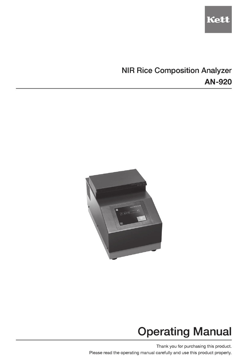
Kett FD-800 User manual

Infrared Moisture Analyzer
FD-800
Operating Manual
Thank you for purchasing this product.
Please read the operating manual carefully and use this product properly.


Safety Notes
Improper use of the infrared moisture tester in violation of the following safety notes may result in death, injury or damage to
property due to re, etc. Furthermore, the infrared moisture tester has high temperature components which can cause burns
if proper safety guidelines are not followed.
n Observe all safety guidelines
Carefully read and observe all safety notes included in this user’s manual.
n Do not use the unit if it appears to be malfunctioning
If you suspect a problem or malfunction in the unit, discontinue use and immediately have the unit inspected by certied Kett
service personnel.
n Meanings of Warning Indicators and Symbols
The following symbols are used in this operating manual and product to prevent accidents from occurring as a result of
improper usage or handling. The meaning of each symbol is as described below.
Warning Failure to observe these items may lead to death or injury to the user.
Caution Failure to observe these items may lead to injury to the user or damage to property.
Note Items which the user should be aware of in order to use the unit safely.
Caution Symbols Stop Symbols Symbols Requiring User Action
Fire Hazard Burn Hazard Electric Shock Prohibited Do Not Do not Expose Required Disconnect Plug
Hazard Disassemble to Water Action from Electrical Outlet
l Do not attempt to measure samples which may undergo dangerous chemical reactions when heated, as doing so
may result in an explosion or release of toxic gas.
l Do not place ammable materials near the infrared moisture tester.
Some parts of the infrared moisture tester become extremely hot during operation and could lead to a re if
ammable materials are placed nearby.
l Never use with any power source for which the product was not designed.
Application of excessively high voltage may result in overheating, malfunction, or re.
l Do not attempt to disassemble, modify or rebuild the infrared moisture tester.
Doing so may result in accident, electric shock, etc. If you believe the unit may be malfunctioning, take it to an
authorized Kett service center for service.
l Do not allow the unit to come in contact with water.
The infrared moisture tester is not waterproof. Do not allow water or other liquids to get into the unit’s enclosure as
this may lead to electric shock or malfunction.
l Do not touch the heat-dispersing component of the heater cover or sample dish with your bare hands, as doing so
might result in burns.
This infrared moisture tester is at high temperature during and immediately after making measurements. When
touching the unit, only use the specied control knobs and accessories.
Warning
Fire Hazard Electric Shock Hazard
Caution
Burn Hazard Electric Shock Hazard

Contents
1. Precautions to be observed when taking measurements .....................6
2. Description of Features and Principles of Operation.............................8
■ Principles of Operation ..............................................................................................8
■ Features .....................................................................................................................8
■ Applications (i.e., materials which can be measured) ...............................................8
3. Specications ............................................................................................9
4. Names of Individual Parts and Components ..........................................10
4-1 Names of Parts of Main Unit ......................................................................................10
4-2 Parts and Accessories ...............................................................................................11
5. Display and Control Panel ........................................................................12
5-1 Display .......................................................................................................................12
5-2 Control Panel Operations ..........................................................................................13
6. Assembly and Installation of Main Unit...................................................14
7. Tips on how to ensure accurate measurements ....................................17
8. How to Conduct Measurements ...............................................................19
9. Specifying Measuring Conditions............................................................23
9-1 Types of Settings .......................................................................................................23
9-2 Descriptions of Individual Measuring Condition Settings ..........................................23
9-2-1 Selecting the CONDITIONS (Measuring conditions storage area) ...............24
9-2-2 Selecting the MODE (Measuring mode) ........................................................25
9-2-3 TEMP (Drying temperature) ..........................................................................34
9-2-4 Bias ................................................................................................................35
10. Menu Settings ............................................................................................36
10-1 Types of Menu Settings .............................................................................................36
10-2 Descriptions of Individual Menu Items .......................................................................36
10-2-1 Selecting units (measurement standard and minimum display units) ...........37
10-2-2 Specifying the type and format of output.......................................................38
10-2-3 Specifying sample codes ..............................................................................41
10-2-4 Specifying an ID (device ID) ..........................................................................42
10-2-5 Setting the date and time ..............................................................................43
10-2-6 CAL (Scale calibration) ..................................................................................44
10-2-7 Specifying a password ..................................................................................46
10-2-8 Specifying the power settings .......................................................................48

11. Error Messages..........................................................................................49
12. Concerning the radiation thermometer ...................................................51
12-1 Radiation thermometer ..............................................................................................51
12-2 Emissivity ...................................................................................................................51
12-3 Radiation thermometer temperature measurement spot ...........................................53
12-4 Relationship of T1 and T2 ..........................................................................................53
12-5 Radiation Thermometer Calibration Kit .....................................................................54
13. Predictive Measurements .........................................................................55
13-1 A Description of Predictive Measuring .......................................................................55
13-2 Procedure for Obtaining Predicted Measurements ...................................................57
13-2-1
Calculating the bias to be specied when operating in predictive measurement mode
....57
13-2-2 Evaluating predicted measurements .............................................................59
13-2-3 Obtaining predicted measurements ..............................................................60
14. Printing Output to a Printer (Option)........................................................61
14-1 Sample Printer Output ...............................................................................................61
14-2 Outputting Past Measurement Data ..........................................................................64
15. Computer Interface....................................................................................65
15-1 RS-232C Interface Specications .............................................................................65
15-2 Setting Up and Transmitting Data ..............................................................................66
15-2-1 Connecting the RS-232C cable .....................................................................66
15-2-2 FD-800 settings .............................................................................................66
15-2-3 Starting up the computer ...............................................................................66
15-3 Computer Output Format ...........................................................................................67
16. Maintenance ...............................................................................................69
16-1 Performing Maintenance ...........................................................................................69
16-2 Replacing Fuses ........................................................................................................70

6
Be sure to follow proper procedures during operation
l
When opening or closing the lid to the heater, always be sure to use the handle.
l
Be sure to put the wind shield, sample dish tray, handler, and sample dishes properly into place. (See “6.
Assembly and Installation of Main Unit” on p. 14 for instructions.)
l
Always be sure to use the provided handler to remove sample dishes.
l
When removing a sample dish, do not allow your hands to come into contact with the heater or any of the
metal (aluminum) parts around the heater, as doing so could result in burns.
l
The sample dish and area around the sample dish will be very hot immediately after performing a mea-
surement. Be sure to place the sample dish in an appropriate place to allow it to cool.
Heater
Never perform measurements using hazardous materials
l
Heating materials which would present a risk of explosion or combustion, or materials which could give off
noxious fumes when heated, is extremely dangerous and this instrument should never be used with any
such materials. The same also applies to the use of any materials which might cause hazardous chemical
reactions to take place when heated.
l
When heating materials that would rst dry along the surface, and then allow the internal pressure to rise
excessively, there is a danger that heating such materials could cause them to rupture. Such materials
should never be measured, as doing so could be dangerous.
l
If any materials being measured ignite, immediately remove the power plug from its socket and take ap-
propriate measures extinguish the re.
Areas to touch and areas subject to high temperatures
l
While a measurement is being performed or immediately after a measurement has been performed, the
areas marked in the accompanying diagrams as HOT will heat up to high temperatures. When handling
the unit, always be sure to allow your hands to come into contact only with the designated areas.
Handle
Handle for holding heater lid
HOT
Place to grasp handler
HOT
HOT
Handler
Sample
dish
1. Precautions to be observed when taking measurements

7
Neverplaceanyeasilyammableobjectsneartheproduct
l
The components of the infrared moisture tester can become very hot when measurements are
being taken or immediately after measurements have been taken. The heat could cause objects
or materials to catch re if they were to come into contact with the unit, an d no easily amma-
ble objects or materials should be kept near the product.
l
Never place any objects which might easily be damaged by heat near the unit, as doing so
might result in deformation or damage to the objects in question.
l
No objects should ever be placed upon the heater.
l
If you see re coming from the unit or notice smoke, an odd smell, or any other sign of abnor-
mal functioning, remove the power plug from its socket, or take whatever other steps would be
appropriate to deal with the problem.
Notes on using the control keys
l
Never turn on the power to the unit while holding down any of the control keys.
l
Never press any keys other than those directed or press two or more keys together at the same
time unless directed to do so.
l
When there is any danger that the unit might be damaged by lightning, remove the power plug
from its socket.
Stopping operation
l
The key can be pressed at any time during operation to halt operation. If you suspect
for any reason that the product is not operating properly or that there is any sort of danger, im-
mediately press the key to halt operation.
Setup and storage
l
Avoid using or storing the unit in a location where it would be exposed to excessively high or low
temperatures, high levels of humidity, direct sunlight, electromagnetic interference, corrosive
gases, or large amounts of dust.
l
Place the unit on a at and stable surface where it will not be subjected to signicant vibration
during use.
l
When moving the unit, never tilt it any more than necessary.
l
Take care never to drop or bump the unit or otherwise allow it to be subjected to strong shocks
or the application of excessive force.
l
When removing the power cord or RS-232C interface cable, never pull on the cord or cable and
instead hold the plug or cable connector when removing.
l
When the unit is not to be used over an extended period of time, remove the power plug from its
socket.

8
■PrinciplesofOperation
This unit determines the moisture and solid contents of samples by heating them using infrared
illumination and measuring changes in mass due to evaporation. This is referred to as the loss on
drying method and is the simplest method for determining moisture content and thus mandated by
many public regulations related to measurement standards.
■Features
lEquipped with a radiation thermometer
In addition to temperature measurement by a conventional thermistor (T1 measurement), it is equipped with a radiation
thermometer that can directly measure the surface temperature of a sample. (T2 measurement*1) This radiation
thermometer permits drying of a sample in a short time with good reproducibility without burning the sample.
lEquipped with a ten-key pad
The ten-key pad is used to enter numbers and letters simplifying entry.
lUniBloc sensor
The core of the scale is formed by a single-unit aluminum UniBloc*2 weight sensor which provides excellent
responsiveness, temperature characteristics, and shock resistance. This UniBloc*1 sensor ensures excellent reliability
in moisture content measurements even over extended use.
lNew Auto Taring mechanism
The FD-800 comes with an internal Auto Taring mechanism which makes it possible to perform reset correction while
performing measurements, thus eliminating drift of the scale even when performing measurements over long periods
of time and making it possible to obtain extremely reliable measurements.
lMid-infrared quartz heating lamp
The FD-800 uses a mid-infrared quartz heating lamp (with a central wavelength of 2.6 μm). This heater provides
excellent drying efciency over a wide range of different types of sample, makes it difcult for differences to occur as
a result of the colors of different samples, and eliminates the overheating of sample surfaces, thus making it possible
to obtain ideal drying conditions.
What‘s more, this heating lamp also provides a long service life 5~10 times greater (20,000 to 30,000 hours*3) than
older infrared or halogen lamps.
lA wide selection of measuring modes
The FD-800 provides a wide selection of measuring modes (automatic halting mode, timed halting mode, high-speed
drying mode, low-speed drying mode, stepped drying mode, and predictive measuring mode) which makes it possible
to perform measurements under the drying conditions most appropriate to the drying characteristics of the sample
being measured.
lThe ability to store measuring conditions
The FD-800 provides 100 measuring conditions storage areas which may be used to store sets of measuring condi-
tions to be used for different types of materials, thus reducing the amount of time involved in specifying settings before
performing measurements.
lData memory
The FD-800 is able to store up to 100 sets of measurement data in memory, thus making it possible to output large
batches of data all at one time.
lScale (and the radiation thermometer) can be calibrated
Scales (and the radiation thermometer) can be calibrated. During calibration, output can be printed in response to the
demand for GLP, GMP, ISO.
*1 Patent pending.
*2 UniBlock is a product name of the Shimadzu Corporation.
*3 Indicates average life of heater but does not guarantee actual life time.
■Applications(i.e.,materialswhichcanbemeasured)
l Materials for which water is the only main component which evaporates as a result of heating
l Materials for which no dangerous chemical reactions or other changes occur as a result of heating
* Measurements can be performed using virtually any material meeting these conditions.
2. Description of Features and Principles of Operation

9
*1 When using standard sample and measuring condition as determined by Kett Electric Laboratory.
*2 If the T1 temperature exceeds 180°C during measurement, it may not reach the set temperature.
*3 It is used for radiation thermometer calibration. For details see the Users Manual that comes with the Radiation Ther-
mometer Calibration Kit.
3.Specications
Measurement format :Evaporation weight loss method (Heat drying and weight loss method)
Sample weight :0.5~120 g using selective weight sampling method
Minimum displayable units :Moisture content (solids): 0.1% or 0.01% (selectable), Weight: 0.001 g
Measurable quantities :Moisture content (wet base & dry base), weight, solid content
Measurement range :0-100% (wet base, solids)
0-500% (dry base)
Reproducibility
(Standard deviation)*1
:Samples with a weight of 5 g or higher: 0.05%
Samples with a weight of 10 g or higher: 0.02%
*1
When using standard samples and measuring conditions as determined by Kett Electric Laboratory.
Measurement modes : Automatic halting mode
Timed halting mode (with measurement times of 1~240 minutes or continuous
measurement mode, with a maximum measurement time of 12 hours)
High-speed drying mode (may be used with either automatic or timed halting mode)
Low-speed drying mode (may be used with either automatic or timed halting mode)
Stepped drying mode (performs drying in 5 steps)
Predictive (comparative) measuring mode
Temperature range :30~180°C in 1-degree increments when using a thermistor (T1)
30~250°C in 1-degree increments when using a radiation thermometer (T2) *2
Display :Backlit LCD display (137 x 43 mm)
External output :RS-232C interface
Communications :FD-800 Data Logger software FDL-02 (option)
Storage of measurement
conditions
:100 sets of measurement conditions
Data memory :100 sets of data
Environmental conditions :Pollution degree 2, Altitude up to 2000 m
Temperature/
humidity operating range
:5~40°C, maximum of 85% RH
Heat source :Medium frequency infrared heater (200W x 2)
Temperature sensor :Thermistor
Power supply,
Power consumption
:AC 100V~120V (50/60 Hz) 900W
AC 220V~240V (50/60 Hz) 900W
Dimensions and weight : 220 (W) x 415 (D) x 220 (H) mm, 5.4 kg
Sample dish :SUS sample dish (Diameter: 130 mm; Depth 13 mm)
Accessories :2 sample dishes, 2 sample dish handlers, wind shield, sample dish tray, spoon &
spatula set, 2 spare (T8A 250V) fuses, 2 packages of aluminum foil sheets (10 per
package), Glass ber sheets (10 sheets), operating manual
Options :Printer set (includes a VZ-330 printer, a printer interface cable (VZC14), printer
paper, and an AC adapter), printer paper (10 rolls), package of aluminum foil
sheets (500 sheets), GF-200 radiation thermometer calibration kit (with a digital
thermometer, heating standard sample) *3, FD-800 Data Logger software FDL-
02 (RS-232C interface cable, USB-RS232C conversion cable), TQ-100 sample
crusher, Deodorizing/windproof case (FW-100), Glass ber sheets (100 sheets)

10
4-1 Names of Parts of Main Unit
Heater lid
Heater
Handle
Observation window
Temperature sensor
(T1 Thermistor)
Display
Level
Wind shield
Sample dish
Sample dish handler
Control panel
Power switch
Power inlet
Fuse holder
Power conversion switch
RS-232C port
Height adjustment legs
Temperature sensor
(T2 Radiation thermometer)
4. Names of Individual Parts and Components

11
4-2 Parts and Accessories
Sample dishes (2) Sample dish handler (2) Wind shield
Sample dish tray Spoon & spatula set Spare (T8A 250V) fuses (2)
(Power cord) (Three-prong plug adapter)
Glass ber sheets Operating manual
(10 per package) (1)
Packages of
aluminum foil sheets
(10 per package) (2)
Note: The shape of the power plug varies in different countries.
The actual accessory may be different from the one in this
illustration.

12
5-1 Display
*Itemsmarkedwithanasteriskdisplayasashingitems.
Display as it appears with the power on. (All display items shown.)
1234&*(!0
5
8
7
6
)
q
=
@
#
$
%
-
^
9
5. Display and Control Panel
Item Name Description
1
Stability indicator This indicator lights up when the internal scale is stable.
2
Measuring complete indicator This indicator lights up when measuring has been completed.
3
Heater on indicator This indicator ashes whenever the heater is turned on.
4
Thermometer selection mark The temperature now indicated is either that provided by the thermistor (T1) or the radiation
thermometer (T2).
5
Predictive measuring indicator This indicator lights up when performing predictive measurements.
6
Predictive measuring indicator
(Lights when performing comparative
measurement)
This indicator lights up when measuring has been completed after performing a comparative
predictive measurement.
7
Shift mark If the key is pressed during alphabetic input, it is displayed (or not displayed). Alphabetic
information can be entered with this mark illuminated.
8
Menu display Used to display individual menu items in sequence each time the key is pressed after pressing
the key.
9
Measuring conditions display Flashes to display individual items in sequence each time the key is pressed after pressing the
key. Values may be specied for a given item when it is ashing.
0
Measuring conditions storage area
display*
Used to display the number of the currently selected measuring conditions storage area.
!
Measuring mode display* Used to display the currently selected measuring mode.
@
Predictive measurement
convergence conditions display*
Used to display the conditions for convergence of measured values when operating in predictive
or comparative mode. When operating in high-speed drying mode, used to display the conditions
required in order to maintain a high-speed drying temperature.
#
Halt conditions display*
Used to display the currently selected halt conditions. When the value is displayed as a percentage,
it indicates that measuring will halt automatically, and when value is displayed in minutes, it indicates
that measuring will halt when the specied amount of time is reached.
$
Drying temperature display* Used to display the currently selected drying temperature.
%
Bias display* Used to display the moisture (or solid) bias.
^
Temperature control switch indicator Indicates whether the temperature control is performed by the thermistor (T1) or the radiation
thermometer (T2).
&
Moisture/Solid/Weight display
When measuring weight (i.e., when in idling mode), used to display the weight in grams. When
performing measurements, used to display the moisture content and solids content as percentages.
When measuring weight, this display is also used to display ‘oL’ (i.e., overload) when the weight
exceeds the maximum measurable weight and to display ‘–oL’ (i.e., no overload) when the weight does
not exceed the maximum measurable weight.
*
Temperature display Used to display the temperature under the heater lid.
(
Measuring time display Used to display the amount of elapsed time or remaining time during measuring.
)
Change in moisture (solid) content
display
Used to display the change (ΔM) in moisture (or solid) content at 30-second intervals during
measurement.
-
Change in moisture (solid) content
scale display
Used to display the change (ΔM) in moisture (or solid) content in scalar format. The scale may display
a maximum change of 2 percent/30 seconds.
=
Heater on LED When the heater is on. it is red.
q
Temperature indicator LED When the temperature is 39°C or less, it is yellow-green, and when it is 40°C or more, it is orange.

13
5-2 Control Panel Operations
The control panel keys are used to perform the following operations.
Name Operation
START/STOP key
Used to start measuring or to abort a measuring operation.
Also used to turn off the alarm which sounds to indicate that a measuring operation has been
completed.
TARE/RESET key
Used to deduct the tare weight.
Also used to perform a reset after an error has occurred.
Also used to return to display of weight after completion of measurement.
ENTER key
Used to conrm currently selected settings.
When further settings must be specied, pressing the ENTER key causes the next specied
item to be displayed; when there are no further settings to be selected, the specied setting is
conrmed and takes effect.
And to enter numerals or letters, use it as an advance key.
SELECT key
Used to select different settings or setting values.
CONDITION key
Used to begin or end the specication of measuring conditions.
MENU key
Used to begin or end the specication of menu settings.
Ten-key/Shift key
The keys are used to enter numerals and letters.
The key is used to switch between numerals and letters.
And it is used to switch between temperature indication (thermistor (T1) and radiation
thermometer (T2)).

14
1Opening the package
Open the package and check to make sure all listed
items are included.
Scale stopper
Sample dish panel
2Installing the main unit
• Place the main unit on a at, stable surface where it
will not be subject to vibrations or exposed to drafts
or breezes.
• Install the main unit so that it is at least 10cm from
the wall both to the front and back and to the left
and right. Make sure there is a space at least 30cm
above the top of the heater cover.
• Do not use it in a closed installation environment.
Depending on the sample, heating may produce
hazardous substances. Install it in a location that
can be adequately ventilated.
4Checking the power settings
Check the power conversion switch located on the
rear of the main unit to make sure that it is currently
set to the proper voltage setting for your power
source.
* Note that an error will occur if this switch is not set to a
position matching the power source being used.
3Removing the stopper from the sample dish panel
When using the unit for the rst time after purchase,
remove the scale stopper attached below the sample
dish panel as indicated in the accompanying diagram.
Power conversion
switch
−
−
100V 220V
120V 240V
6. Assembly and Installation of Main Unit

15
▲Level is located to the left of the control panel.
Knobs
Round
holes
Stays
Sample dish panel
Grooves
Stay
8Attaching the sample dish handler
Next, attach the sample dish handler, being sure
when you do so that the grooves of the handler t
smoothly over the projection located at the rear of the
wind shield.
* While the sample dish handler is shown with the
handle being placed to the right in the diagram shown
here,thehandlemaybeplacedeithertotheleftor
right,andyoushouldaccordinglyplacethehandlein
thepositionyoundeasiesttouse.
7Attaching the sample dish tray
Place the sample dish tray gently into the sample dish
panel at the center of the main unit, being sure when
you do so that the round hole of the sample dish tray
t smoothly over the stay on the sample dish panel.
6Installing the wind shield
Open the lid of the heater, hold the wind shield by the
knobs on the top, and place it on top of the sample
dish panel so that the two round holes in the wind
shield t over the stays of the sample dish panel.
* Placethewindshieldrmlyintopositionsothatitdoes
not come into contact with the black projection located
at the center of the main unit (sample dish panel).
5Ensuring that the unit is level
Turn the two height adjustment legs located at both
sides of the lower rear of the unit to adjust until the
level bubble falls within the red circle.
* The level is located to the left of the control panel.
The tester is perfectly level if the bubble appears in
the center of the red circle when viewed from directly
above.
Not level Level
lBubble
⇒
Height
adjustment
legs
Sample dish
panel
Round hole
Stays

16
9Placing the sample dish into the tester
Please the sample dish gently down onto the sample
dish tray.
0Close the heater lid
!Connecting the power cord
Insert the female end of the power cord into the
power inlet located at the rear of he unit. Then insert
the power plug into the power outlet. Connect the
plug to a power outlet in an easily accessed location
so that it can be pulled out immediately if there are
any problems with the infrared moisture tester. And
be sure to always ground the main unit. If there is
no grounding terminal on the power outlet, use a
grounding adapter. The shape of the power plug
varies in different countries. Use a power cord set
suited to the shape of the plug that you actually use.
@Connecting the printer (sold separately)
If you are using a printer, connect the printer using
the provided printer interface cable. For instructions
on how to use the printer, see the separately provided
VZ-330 Printer User’s Manual.
Assembly is now complete.
* Somepartsmustbeorientedinaxeddirection
for assembly. Note that placing parts in the wrong
direction may result in errors in operation or in
erroneousreadingsbeingobtained,andthatyou
should take care that all parts are put into place in their
proper positions.

17
lPoints to remember when conducting multiple measurements in succession
1. Placing a sample onto a sample dish which is already warm may cause moisture from the sample to
evaporate before measuring is begun and cause errors to occur in measurement. Always be sure to
use a cool sample dish when performing a second or subsequent measurements.
You should also take care to allow an even amount of time to elapse between measurements, as
errors in measurement may occur if the temperature of the internal scale of the unit does not remain at
a constant level.
* Two sample dishes and two sample dish handlers are included.
2. Keep the measurement interval as regular as possible. if the temperature inside the measurement
device is not constant, measurement errors may occur. When the temperature indicator LED changes
from orange to yellow-green, set the criterion for starting a re-measurement as (39°C or less).
* The indicated temperature at this time must be preset as the T1 display. Switching between T1 and T2 is
done by pressing the key.
3. At the rst measurement of the day or when the unit cools during an interval between measurements,
discard the rst measured value and use the second and subsequent measurements.
lUse of sample dishes and aluminum foil sheets
It is impossible to obtain accurate measurements if residue from the sample last measured remains
on the sample dish. To avoid such problems, either wipe the sample dish clean of any dirt or soil (see
“16. Maintenance” on p. 69 for further instructions) or use disposable aluminum foil sheets to protect
against residues, soil, or dirt.
* Twenty disposable aluminum foil sheets are included with the unit.
lQuantityandplacementofpowdered,particulateandviscoussamplematerials
The easier it is to heat the surface of a sample material, the easier it is for projecting portions of the
material or for material at the top of a mound of material to become burnt. If the material is placed in a
mound on the dish or if the material is not at and evenly laid out, this is likely to happen, thus making
it impossible to obtain accurate measurements.
Note that while the precision of measurement improves the more atly and evenly samples are placed
and the higher the amount of sample material used, the quantity of sample material used is too great if
the surface becomes burned before lower layers are fully dried.
Always be sure to lay out samples atly and evenly as indicated in the diagram below.
To make a measurement by radiation thermometer control (T2), be sure to do so with the specimen
in the center of the (thermometer side) spot (specimen is embedded horizontally). Because the
temperature of the sample tray (SUS) may be detected when part of the sample tray can be seen in
the spot, a measurement error may occur.
* AnSUStrayhasalowemissivity,soitsdetectiontemperatureisalsolow.
When because of the state or shape of the sample, part of the sample tray is unavoidably visible
inside the spot, (dry noodles, or brous materials, etc.), lay down the attached glass ber sheet so
that the sample tray cannot be seen to make the measurement. (see “12-3 Radiation thermometer
temperature measurement spot” on p. 53 for further instructions)
Proper placement Incorrect placement
7. Tips on how to ensure accurate measurements

18
lMeasuring liquid samples
Virtually all liquid materials will coagulate after being dried, and when working with such materials
they should be placed on the provided sheets of aluminum foil. Note that these aluminum foil sheets
are water-permeable, thus making it possible to obtain wide and even placement and making them
effective for use in shortening measuring times and obtaining accurate measurements.
Depending on the sample in question, the use of the attached glass ber sheet or of sand to speed up
drying (Silica sand or ocean sand with a mesh of 20 or so) may be even more effective.
lCrushing samples consisting of large particles before measuring
If samples consisting of large particles are measured in their original
condition it not only takes longer for drying to completed to the center, but
also may result in problems such as the surface of the sample becoming
burned, thus making it impossible to obtain accurate measurements.
For this reason you should always crush samples to an appropriate size.
The TQ-100 Sample Crusher (option) is excellent for this purpose.
lRemove sample residue and other dirt.
Depending on the sample, oil and volatile substances may stick to
the temperature sensor and in the inside of the heater base when the
sample is being dried. If the sample is in the form of a powder, under
certain circumstances, the powder may accumulate on the upper side
of the heater lid or in the space between the heater and lid. Such sub-
stances and powder can change the temperature around the sample
and the air ow in the dryer section of the machine, resulting in an
error in measured moisture.
A substantial error can especially arise if the upper side of the heater
lid gets clogged with deposited material.
Frequently clean the apical end of the sensor, the inside of the heat-
er base, the upper side of the heater lid, and the space between the
heater and lid, and remove any dirt or sample residue.
l
Wipe off the dirt with a dry, soft cloth.
l
If dirt remains, wipe with a cloth wringed well after being soaked
in water mixed with a little amount of neutral detergent. Then, dry
after rinsing the cloth in running water, wringing it well, and wiping
off the detergent.
lDeodorizing windproof case
If the impact of exterior wind (from air-conditioners etc.) on the body is
unavoidable or if the sample gives a bad odor during moisture content
measurement, it is possible to lower these impacts by placing the device
inside the deodorizing windproof case FW-100 (option).
TQ-100 Sample Crusher
FW-100 Deodorizing
Windproof Case
Upper side of the heater lid
Inside of the heater base
Space of the heater base
Apical end of the
Temperature sensor

19
Before beginning a measurement, check to make sure that there is nothing remaining in the sample
dish. Also be sure that all parts of the main unit are rmly xed in place and be sure that the heater
lid has been closed rmly before starting to perform measurements.
Also be sure to check on a regular basis that the main unit is level and readjust the height
adjustment legs if necessary. (See “6. Assembly and Installation of Main Unit” on p. 14 for
instructions on how to do so.)
8. How to Conduct Measurements
Operating instructions Display
1Turn on the power switch
Turn on the power switch located at the rear of the unit.
When you turn on the power for the rst time after purchasing your tester,
a tone will sound, the display will light up with all items lit and then change
to display rst ‘CHE5’ and then a string of dashes (i.e., ‘- - - - -’).
At the bottom left of the display will be displayed the power settings
specied (as described in step 4 of “6. Assembly and Installation of Main
Unit” on p. 14) with the display reading ‘100V’ when the power settings
have been set to 100~120V and reading ‘220V’ when they have been set
to 220~240V.
If using the tester in a country that does not use 100V power, then this
is the time when you should specify the power settings to be used. (See
step 3 of “10-2-8 Specifying the power settings” on p. 47 for instruction
on how to do so.)
* WhenusingthetesterinJapan,thesettingsshouldbeleftunchanged.Check
to make sure that the display reads ‘100V’ and then press the key.
Asthepowersettingcontinuestobedisplayedinthelowerleftofthedisplay,
thecenterofthedisplaywillchangetodisplay‘CHE4’,‘CHE3’,...,‘CHE0’and
a tone will sound and the display will change to weight reading display mode.
* Whenthepoweristurnedonforthesecondorsubsequenttimes,atone
willsound,thedisplaywilllightupwithallitemslit,thedisplaywillchange
todisplay‘CHE5’,‘CHE4’,...,‘CHE0’whilethecurrentlyspeciedpower
settingisdisplayed,andthenatonewillsoundagainandthedisplaywill
change to weight reading display mode.
* Note that it is recommended that you always turn on the tester about half an
hour before use in order to obtain consistent measurements.
.
.
.
* Display will show default settings at
thetimeofshipment.(Seep.24,“9-2-1
Selecting the CONDITIONS (Measuring
conditions storage area)”.)
2Specifying settings
When performing measurements for the rst time, or when you wish to
change current settings before measuring, then you should specify the
settings required for measuring here. (See “9. Specifying Measuring
Conditions” on p. 23 and “10. Menu settings” on p. 36 for instructions on
how to do so.)
3Placing the sample dish in the tester
Open the heater lid, place the sample dish on the handler, and place the
handler into the tester, being sure when you do so that the grooves of the
handler t smoothly over the projection located at the rear of the wind
shield.
* Ifyouhavealreadyplacedthesampledishandhandler(asdescribedin“6.
AssemblyandInstallationofMainUnit”)thenproceeddirectlytothenextstep.
* Whenusinganaluminumfoilsheet,glassberorotherwrappingbecause
ofthenatureofthesamplebeingmeasured,placethewrappingontopof
the sample tray.
Grooves
Stays

20
Operating instructions Display
4Performing a tare
Shut the heater lid, check to make sure that the steady-state mark ( ) is
displayed, and press the key. A series of hyphens and the word
‘TARE’ will be displayed, the sample dish will move vertically and a tare
will be performed. A sharp tone will then sound and the word ‘TARE’ will
disappear from the display, a weight of ‘0.000 g’ will be displayed and the
tare will then be complete.
* Always be sure that the heater lid is closed when performing a tare. Also
makesurethatthetesterisnotexposedtodraftsorbreezes,orsubjectedto
any vibrations when a tare is being performed.
5Placing a sample in the tester
Open the lid to the heater and place the sample inside.
Be sure to place the sample as atly as possible into the tester so that
heat is applied evenly to the sample during measurement. (See “7. Tips on
how to ensure accurate measurements” on p. 17 for further information.)
6Beginning measurement
Close the lid of the heater, check to make sure that the stability indicator
() is being displayed, and then press the key. The display will
switch from a display of the weight (i.e., grams) to a percentage display
and the measuring time will be displayed.
The heating indicator LED will light up red and the heater mark ( ) will
ash on the indicator, and drying will start.
* There may be times when the stability indicator ( ) is not displayed because
ofexternalvibrationsordraftsorbreezes.Whileitispossibletoperform
measurementsatsuchtimes,theremaybecaseswhenitisimpossibleto
obtain accurate measurements at such times. You should always be sure
toconductmeasurementsinalocationasfreeaspossibleofvibrations,
drafts,breezes,oranyotherharmfulinuences.
Table of contents
Other Kett Measuring Instrument manuals
Popular Measuring Instrument manuals by other brands

attension
attension Theta user manual

Dwyer Instruments
Dwyer Instruments 477-000-FM Installation and operating instructions

EDT
EDT RE357TX instruction manual

PCE Instruments
PCE Instruments PCE-DOM Series user manual

PCB Piezotronics
PCB Piezotronics ICP J356A44 Installation and operating manual

Extech Instruments
Extech Instruments HD300 user guide