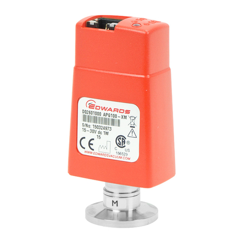
Edwards AIM-S-NW25 User manual

D145-45-885
Issue H
Instruction Manual / Betriebsanleitung / Mode d'emploi
Active Inverted Magnetron Gauge
Aktiv-Penning-Meßröhren
Jauge active Magnétron inverse
Description
Beschreibung
Description
Item Number
Bestellnummer
Numéro de Référence
AIM-S-NW25 D145-45-000
AIM-SL-NW25 D145-48-000

This product
has been manufactured under a quality system registered to ISO9001
Declaration of Conformity
We, Edwards,
Manor Royal,
Crawley,
West Sussex, RH10 9LW, UK
declare under our sole responsibility, as manufacturer and person within the EU authorised to assemble the technical file, that the product(s)
Active Inverted Magnetron Gauge:
AIM-S-NW25 D145-45-000
AIM-SL-NW25 D145-48-000
to which this declaration relates is in conformity with the following standard(s) or other normative document(s)
EN61010-1: 2001 Safety Requirements for Electrical Equipment for Measurement, Control and Laboratory Use. General Requirements
EN 61326-1: 2006 Electrical equipment for measurement, control and laboratory Use. EMC requirements. General requirements.
and fulfils all the relevant provisions of
2004/108/EC Electromagnetic Compatibility (EMC) Directive
Note: This declaration covers all product serial numbers from the date this Declaration was signed onwards.
P200-02-580 Issue B
Date and Place
Sia Abbaszadeh, Chief Technical Office
r
9 December 2009

Dieses Produkt wurde gemäß einem nach
ISO9001
zertifizierten Qualitätsmanagementsystem gefertigt.
Konformitätserklärung
Wir, Edwards,
Manor Royal,
Crawley,
West Sussex, RH10 9LW, UK
erklären in alleiniger Verantwortung als Hersteller und Person, die innerhalb der EU zur Zusammenstellung der technischen Unterlagen befugt ist,
dass das Produkt bzw. die Produkte
Aktiv-Penning-Meßröhren:
AIM-S-NW25 D145-45-000
AIM-SL-NW25 D145-48-000
auf das bzw. auf die sich die vorliegende Erklärung bezieht, im Einklang steht bzw. stehen mit der (den) folgenden Norm(en) oder (einem)
anderen normativen Dokument(en):
EN 61010-1: 2001 Sicherheitsbestimmungen für elektrische Mess-, Steuer-, Regel- und Laborgeräte. Allgemeine Anforderungen
EN 61326-1: 2006 Elektrische Mess-, Steuer- und Laborgeräte. EMV-Anforderungen. Allgemeine Anforderungen
und alle einschlägigen Vorschriften erfüllt aus
2004/108/EG Richtlinie zur elektromagnetischen Verträglichkeit (EMV-Richtlinie)
Hinweis: Diese Erklärung gilt für alle Produktseriennummern ab dem Unterzeichnungsdatum dieser Erklärung.
Sia Abbaszadeh, Chief Technical Officer Datum und Ort
P200-02-582 Issue B
16 December 2009

Ce produit a été réalisé en respectant un système de qualité homologué conformément à la norme ISO9001
Déclaration de conformité
Nous, la société Edwards,
Manor Royal,
Crawley,
West Sussex, RH10 9LW, R.U.
déclarons sous notre entière responsabilité, en tant que fabricant et personne établie dans l'UE et autorisée à constituer le dossier technique, que
le ou les produit(s) suivant(s)
Jauge active magnétron inverse :
AIM-S-NW25 D145-45-000
AIM-SL-NW25 D145-48-000
au(x)quel(s) cette déclaration se réfère est ou sont conforme(s) à la ou aux norme(s) suivante(s) ou à un ou plusieurs autre(s) document(s)
normatif(s)
EN61010-1: 2001 Règles de sécurité pour appareils électriques de mesurage, de régulation et de laboratoire. Prescriptions générales.
EN 61326-1: 2006 Matériels électriques de mesure, de commande et de laboratoire. Prescriptions relatives à la CEM. Prescriptions
générales.
et est ou sont conforme(s) aux clauses pertinentes de
2004/108/CE Directive sur la compatibilité électromagnétique (CEM)
Remarque : la présente déclaration couvre tous les numéros de série à partir de la date de sa signature.
P200-02-583 Issue B
Date et lieu
Sia Abbaszadeh, responsable technique principal
9 December 2009

Diese Seite bleibt absichtlich frei.

Cette page est délibérément laissée vierge.

© Edwards Limited 2012. All rights reserved. i
Edwards and the Edwards logo are trademarks of Edwards Limited.
D145-45-885 Issue H
Contents / Inhalt / Table des matières
Contents
Section Page
1 Introduction ..........................1
1.1 Scope and definitions ........................ 1
1.2 Description ..................................... 2
1.3 Gas dependency ............................... 5
2 Technical data .......................7
2.1 Mechanical data ............................... 7
2.2 Performance, operating and storage
conditions ...................................... 7
2.3 Electrical data ................................. 8
2.4 Materials exposed to vacuum ............... 9
3 Installation .......................... 11
3.1 Unpack and inspect ..........................11
3.2 Fit the AIM Gauge to the
vacuum system ...............................11
3.3 Electrical connections .......................12
3.3.1 Connect to Edwards controllers or
AGD display ...................................13
3.3.2 Connect to your own supply and
control equipment ...........................13
4 Operation ........................... 17
4.1 Safety ..........................................17
4.2 Enable and disable the AIM Gauge ........18
4.3 Pressure measurement ......................18
4.4 Error output signal ...........................19
gea/0202/04/12
Inhalt
Abschnitt Seite
1 Einleitung .............................1
1.1 Ziel und Definitionen .........................1
1.2 Beschreibung ...................................2
1.3 Gasart-Abhängigkeit ..........................5
2 Technische Daten ....................7
2.1 Mechanische Daten ............................7
2.2 Leistungs-, Betriebs- und
Lagerbedingungen .............................7
2.3 Elektrische Daten ..............................8
2.4 Werkstoffe im Vakuum .......................9
3 Installation .......................... 11
3.1 Auspacken und Kontrollieren .............. 11
3.2 Montage der AIM-Meßröhre in das
Vakuumsystem ............................... 11
3.3 Elektrische Anschlüsse ...................... 12
3.3.1 Anschluß an Edwards-Controller
oder AGD-Anzeigegerät ..................... 13
3.3.2 Anschluß an eigene Netzversorgung
und eigene Steuerung ....................... 13
4 Betrieb ............................... 17
4.1 Sicherheit ..................................... 17
4.2 Zulässiger Betriebsbereich
der AIM-Meßröhre ........................... 18
4.3 Druckmessung ................................ 18
4.4 Fehlerausgangssignal ........................ 19
Table des matières
Section Page
1 Introduction ..........................1
1.1 Portée et définition ...........................1
1.2 Description .....................................2
1.3 Dépendance par rapport au gaz .............5
2 Caractéristiques techniques .......7
2.1 Caractéristiques mécaniques ................7
2.2 Performances et conditions de
fonctionnement et de stockage .............7
2.3 Caractéristiques électriques .................8
2.4 Matériaux exposé au vide ....................9
3 Installation ..........................11
3.1 Déballage et vérification ................... 11
3.2 Montage de la jauge AIM
sur le système à vide ........................ 11
3.3 Raccordements électriques ................ 12
3.3.1 Raccordement à des contrôleurs
Edwards ou à un coffret
d’affichage AGD ............................. 13
3.3.2 Raccordement à votre propre
matériel et équipement de contrôle ..... 13
4 Fonctionnement ....................17
4.1 Sécurité ....................................... 17
4.2 Activation et désactivation
de la jauge AIM .............................. 18
4.3 Mesures de pression ......................... 18
4.4 Signal de sortie d’erreur ................... 19

ii © Edwards Limited 2012. All rights reserved.
Edwards and the Edwards logo are trademarks of Edwards Limited.
D145-45-885 Issue H
Contents / Inhalt / Table des matières
5 Maintenance ........................ 21
5.1 Introduction ..................................21
5.2 Replace the body tube ......................22
5.2.1 Remove the AIM Gauge from the
vacuum system ...............................22
5.2.2 Fit the new body tube ......................22
5.2.3 Refit the AIM Gauge to the
vacuum system ...............................24
5.3 Replace the electrode assembly ...........24
5.4 Replace the electronics
and magnet housing .........................25
5.5 Clean the internal components ............26
5.6 Fault finding ..................................27
6 Storage and disposal .............. 29
6.1 Storage ........................................29
6.2 Disposal ........................................29
7 Spares and accessories ............ 31
7.1 Introduction ..................................31
7.2 Spares ..........................................32
7.3 Accessories ....................................33
For return of equipment, complete the HS Forms at the
end of this manual.
5 Wartung ............................. 21
5.1 Einleitung ..................................... 21
5.2 Austausch des Meßröhrenkörpers ......... 22
5.2.1 Ausbau der AIM-Meßröhre aus dem
Vakuumsystem ............................... 22
5.2.2 Einbau des neuen Meßröhrenkörpers ..... 22
5.2.3 Einbau der AIM-Meßröhre ins
Vakuumsystem ............................... 24
5.3 Austausch der Elektrodengruppe .......... 24
5.4 Ausbau der Meßelektronik und des
Magnetgehäuses ............................. 25
5.5 Reinigung der internen Komponenten .... 26
5.6 Fehlersuche .................................. 27
6 Lagerung und Entsorgung ......... 29
6.1 Lagerung ...................................... 29
6.2 Entsorgung .................................... 29
7 Ersatzteile und Zubehör .......... 31
7.1 Einleitung ..................................... 31
7.2 Ersatzteile .................................... 32
7.3 Zubehör ....................................... 33
Bitte die HS-Formulare im Anhang dieses Handbuchs
ausfüllen und Ihrer Rücksendung beilegen.
5 Entretien .............................21
5.1 Introduction .................................. 21
5.2 Remplacement du tube ..................... 22
5.2.1 Dépose de la jauge AIM du
système à vide ............................... 22
5.2.2 Mise en place d’un tube neuf .............. 22
5.2.3 Remontage de la jauge AIM sur le
système à vide ............................... 24
5.3 Remplacement de
l’ensemble électrode ....................... 24
5.4 Remplacement de l’électronique et du
logement de l’aimant ....................... 25
5.5 Nettoyage des composants internes ...... 26
5.6 Recherche des causes de panne ........... 27
6 Stockage et mise au rebut ........29
6.1 Stockage ...................................... 29
6.2 Mise au rebut ................................. 29
7 Pièces détachées et accessoires .31
7.1 Introduction .................................. 31
7.2 Pièces détachées ............................ 32
7.3 Accessoires ................................... 33
Pour le retour d'équipements, complétez les
formulaires HS à la fin de ce manuel.

© Edwards Limited 2012. All rights reserved. iii
Edwards and the Edwards logo are trademarks of Edwards Limited.
D145-45-885 Issue H
Contents / Inhalt / Table des matières
Illustrations
Figure Page
1 General view of the AIM Gauge
(showing the NW25 flange) .................. 4
2 Dimensions (mm) ............................ 10
3 Schematic diagram of typical electrical
connections ...................................14
4 Exploded view of the AIM Gauge ..........23
Tables
Table Page
1 Pins on the AIM Gauge electrical
connector socket .............................15
2 Pressure and voltage characteristics
for nitrogen and dry air .....................20
Abbildungen
Abbildung Seite
1 Allgemeine Ansicht der AIM-Meßröhre
(mit Flansch NW25) ...........................4
2 Abmaße (mm) ................................ 10
3 Schaltschema der typischen
elektrischen Anschlüsse .................... 14
4 Explosionsdarstellung der
AIM-Meßröhre ................................ 23
Tabellen
Tabelle Seite
1 Pinbelegung an der Anschlußbuchse
für die AIM-Meßröhre ....................... 15
2 Druck- und Spannungswerte für
Stickstoff und trockene Luft ............... 20
Illustrations
Illustration Page
1 Vue générale de la jauge AIM
(avec la bride NW25) ..........................4
2 Dimensions (mm) ............................ 10
3 Schéma des raccordements électriques
types ........................................... 14
4 Vue éclatée de la jauge AIM ............... 23
Tableaux
Tableau Page
1 Identification des broches de la prise
de raccordement électrique
de la jauge AIM .............................. 15
2 Caractéristiques de pression et de
tension pour l’air sec et pour l’azote .... 20

iv © Edwards Limited 2012. All rights reserved.
Edwards and the Edwards logo are trademarks of Edwards Limited.
D145-45-885 Issue H
This page has been intentionally left blank. Diese Seite bleibt absichtlich frei. Cette page est délibérément laissée vierge.

Introduction / Einleitung / Introduction
© Edwards Limited 2012. All rights reserved. 1
Edwards and the Edwards logo are trademarks of Edwards Limited.
D145-45-885 Issue H
1Introduction
1.1 Scope and definitions
This manual provides installation, operation and
maintenance instructions for the Edwards AIM Gauge
(Active Inverted Magnetron Gauge). You must use the
AIM Gauge as specified in this manual.
Read this manual before you install and operate the AIM
Gauge. Important safety information is highlighted as
WARNING and CAUTION instructions; you must obey
these instructions. The useof WARNINGS and CAUTIONS
is defined below.
CAUTION
Cautions are given where failure to observe the
instruction could result in damage to the equipment,
associated equipment or process.
The units used throughout this manual conform to theSI
international system of units of measurement.
WARNING
Warnings are given where failure to
observe the instruction could result in
injury or death to people.
1 Einleitung
1.1 Ziel und Definitionen
Diese Betriebsanleitung enthält Installations-, Betriebs-
und Wartungsanleitungen für die Edwards-Aktiv-
Penning-Meßröhren AIM. Verwenden Sie bitte die AIM
entsprechend den Anleitungen dieser
Betriebsanleitung.
Lesen Sie diese Betriebsanleitung vor Installation und
BetriebderAIM-Meßröhre.WichtigeSicherheitsangaben
sind durch WARNUNGS- und VORSICHTS-Anweisungen
hervorgehoben. Bitte befolgen Sie diese Anweisungen.
Die Verwendung von WARNUNGS- und VORSICHTS-
Anweisungen ist nachfolgend definiert.
VORSICHT
Mit Vorsicht werden Anweisungen gekennzeichnet,
die unbedingt befolgt werden müssen, um Schäden
an Ausrüstungen, angeschlossenen Ausrüstungen
oder Fehler im Gesamtprozeß zu vermeiden.
Die in diesem Handbuch durchgehend verwendeten
Maßeinheiten entsprechen dem internationalen
Maßeinheitensystem SI.
WARNUNG
Mit Warnung werden Anweisungen
gekennzeichnet, die unbedingt befolgt
werden müssen, um Verletzungen oder
Tod von Personen zu vermeiden.
1Introduction
1.1 Portée et définition
Ce manuel présente les consignes de montage,
d’exploitation et d’entretien de la jauge AIM Edwards
(jauge active Magnétron inverse). Vous devez utiliser la
jauge AIM comme il est indiqué dans ce manuel.
Lisezce manuel avantd’installeretde faire fonctionner
la jauge AIM. Les informations de sécurité importantes
sont mises en valeur par des paragraphes encadrés
intitulés AVERTISSEMENT et ATTENTION. Vous devez en
respecter les consignes. L’utilisation de ces messages
AVERTISSEMENT et ATTENTION est définie ci-dessous.
ATTENTION
Un message Attention est prévu chaque fois que le
non respect d’une consigne risque d’endommager
l’équipement, le matériel associé ou le procédé.
Les unités utilisées tout au long de ce manuel sont
conformes au système international SI d’unités de
mesure.
AVERTISSEMENT
Un message Avertissement est prévu
chaque fois que le non respect d’une
consigne risque d’entraîner mort ou
blessure.

Introduction / Einleitung / Introduction
2© Edwards Limited 2012. All rights reserved.
Edwards and the Edwards logo are trademarks of Edwards Limited.
D145-45-885 Issue H
In accordance with the recommendations of EN61010,
the following warning symbol also appears on the
product:
1.2 Description
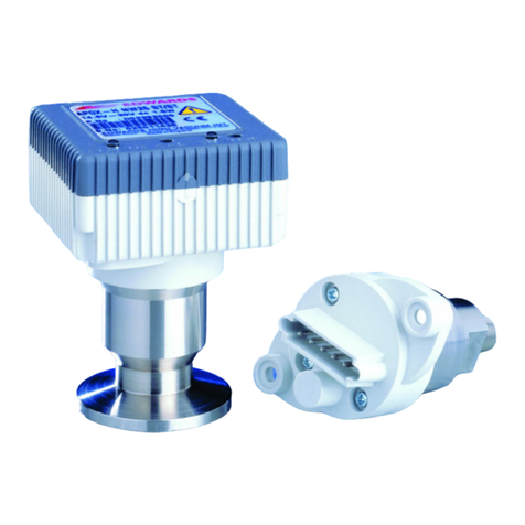
The AIM Gauge, shown in Figure 1, is an inverted
magnetron gauge head and gauge controller in a single
compact unit. The gauge operates as a cold cathode
ionisation gauge, in which the pressure is measured
indirectly as a function of the current which flows in a
Townsend discharge maintained in the body tube.
Two versions of AIM Gauge are available; the ‘S’ gauge
and the ‘SL’ gauge. The ‘SL’ gauge has a very low
external magnetic field and is suitable for use with
sensitive analytical instrumentation.
The measurement range of the AIM Gauge is 1 x 10⁻⁸ to
1 x 10⁻² mbar. The AIM Gauge vacuum connection is an
NW25 flange.
The AIM Gauge requires a 13.5 to 36 V d.c. power
supply: it has a 2 to 10 V d.c. analogue output which is
related to pressure. The AIM Gauge is compatible with
all of the Edwards AGCs (Active Gauge Controllers) and
with the appropriate versions of the Edwards AGDs
(Active Gauge Displays). Alternatively, you can use an
independent power supply for the AIM Gauge and you
From August 2005, Edwards will offer
European customers a recycling service.
Gemäß den EN61010-Empfehlungen ist an dem Produkt
das folgende Warnsymbol angebracht:
1.2 Beschreibung
Die in Abbildung 1 dargestellte AIM Meßröhre ist ein
invertierter Magnetronmeßkopf und integrierte
Meßelektronik in einem einzigen kompakten Gerät. Sie
arbeitet als Kaltkathoden-Ionisierungsmeßgerät mit
indirekter Druckmessung als Funktion des Stromes, der
in einer im Röhrenkörper aufrechterhaltenen Townsend
Entladung fließt.
Die AIM Meßröhre ist in zwei Ausführungen erhältlich:
den Modellen "S" und "SL". Die "SL" Meßröhre hat ein sehr
niedriges externes Magnetfeld und eignet sich für den
Einsatz mit empfindlichen Analyseinstrumenten.
Der Meßbereich der AIM-Meßröhre beträgt 1x10⁻⁸ bis
1x10⁻² mbar. Die Meßröhre hat einen NW25
Anschlußflansch.
Die AIM-Meßröhre erfordert eine Gleichspannungs-
versorgung von 13,5 bis 36 V; die Meßröhre hat einen
druckabhängigenGleichspannungs-Analogausgangvon2
bis 10 V. Die AIM-Meßröhre ist mit allen Edwards-AGC
(Aktiv-Controller) Geräten und den entsprechenden
Versionen der Edwards-AGD (Anzeigegeräte für Aktiv-
Meßröhren) kompatibel. Es ist jedoch auch möglich,
Ab August 2005 bietet Edwards seinen
europäischen Kunden einen
Wiederaufbereitungsservice an.
Conformément aux recommandations de la norme
EN61010, le symbole d'avertissement suivant figure
également sur le produit :
1.2 Description
La jauge AIM qui est illustrée à la Figure 1 est une tête
de jauge Magnétron inversée associée à un contrôleur
de jauge, et le tout est implanté dans un groupe
compact. Cette jauge fonctionne suivant le principe de
l’ionisation cathodique à froid, c’est-à-dire que la
pression est mesurée indirectement, en fonction du
courant qui circule dans une décharge Townsend
maintenue à l’intérieur du tube du corps.
Il existe deux versions de cette jauge AIM : la jauge "S"
et la jauge "SL". La jauge "SL" a un champ magnétique
externe très faible et convient parfaitement à une
utilisation avec des instruments analytiques très
sensibles.
La gamme de mesure de la jauge AIM va de 1 x 10⁻⁸ à
1 x 10⁻² mbar. La jauge AIM a un raccordement de vide
à bride NW25.
La jauge AIM requiert une alimentation de 13,5 à 36 V
CC. Elle comporte une sortie analogique de 2 à 10 V CC,
liée à la pression. La jauge AIM est compatible avec tous
les AGC Edwards (Contrôleurs pour jauges actives) et
A partir d'août 2005, Edwards proposera
un service de recyclage à ses clients
européens.

Introduction / Einleitung / Introduction
© Edwards Limited 2012. All rights reserved. 3
Edwards and the Edwards logo are trademarks of Edwards Limited.
D145-45-885 Issue H
can read the AIM Gauge output signal with a voltmeter
or an analogue-to-digital converter.
We recommend that you do not operate the AIM
Gauge unless the pressure in the vacuum system is
1 x 10⁻² mbar or lower. A gauge enable signal is used to
control the operation of the AIM Gauge; refer to
Section 4.2 for more information.
An 8-way electrical connector socket on the AIM Gauge
(Figure 1, item 6) is used to connect the AIM Gauge to
your AGC, AGD or electrical supply and voltmeter.
Electrical cables fitted with suitable connector plugs
are available as accessories.
A gauge identification signal is available on the
electrical connector: this signal is used by Edwards
AGCs to identify which type of Active Gauge is
connected.
The AIM Gauge has self-monitoring fault detection
circuits. When these circuits detect that the AIM Gauge
is not operating correctly, an error signal is set; this
error signal is available on the electrical connector. The
device which sets the error signal is an FET transistor
which acts like a switch. When no error is detected, the
output of the transistor is on (closed or low impedance).
When the fault detection circuits detect an error, the
transistor output changes to off (open or high
impedance). Note that, if you use a Edwards AGC
controller or AGD display, the AIM Gauge error signal is
not used.
eine unabhängige Stromversorgung für die Meßröhre zu
verwenden und das AIM-Ausgangssignal mit einem
Voltmeter oder über einen Analog-Digital-Wandler
abzulesen.
Wir empfehlen, daß Sie die AIM-Meßröhre nur dann
einsetzen, wenn der Druck im Vakuumsystem
1 x 10⁻² mbar ist. Der Betrieb der AIM-Meßröhre wird
über ein Freigabesignal gesteuert; siehe Abschnitt 4.2
für weitere Informationen.
Eine 8-polige Anschlußbuchse (Abbildung 1, Pos. 6) an
der AIM-Meßröhre wird für den Anschluß an Ihre Aktiv-
Controller, Anzeigegeräte für Aktiv-Meßröhren oder
elektrische Versorgung und Voltmeter verwendet. Mit
passenden SteckernverseheneKabel stehenalsZubehör
zur Verfügung.
Auf dem elektrischen Stecker ist ein Signal zur
Identifizierung von Meßröhren verfügbar. Mit Hilfe
dieses Signals stellt der Edwards AGC den
angeschlossenen Meßröhrentyp fest.
Die AIM-Meßröhre hat selbstüberwachende
Fehlerschaltkreise. Wenn diese Schaltungen melden,
daß die Meßröhre nicht korrekt arbeitet, wird ein
Fehlersignal gesetzt; dieses Fehlersignal liegt am
Stecker an. Gesetzt wird das Fehlersignal durch einen
FETTransistor,der wieeinSchalter arbeitet.Wennkein
Fehler anliegt, ist der Ausgang des Transistors
eingeschaltet (geschlossen oder niederohmig). Bei
Erkennung und Meldung eines Fehlers wird der
Transistorausgang ausgeschaltet (offen oder
hochohmig). Es ist zu beachten, daß bei Verwendung
eines Edwards-AGC-Controllers oder -AGD-
Anzeigegeräts das Fehlersignal der AIM-Meßröhre nicht
verwendet wird.
avec la version correspondante des AGD de Edwards
(Coffrets d’affichage pour jauges actives). Vous pouvez
également utiliser une alimentation indépendante pour
la jauge AIM, et vous pouvez lire le signal de sortie de
la jauge AIM avec un voltmètre ou un convertisseur
analogique-numérique.
Nous vous recommandons de ne pas faire fonctionner la
jauge AIM tant que la pression du système à vide n’est
pas inférieure ou égale à 1 x 10⁻² mbar. Un signal de
validation de la jauge permet d’en contrôler le
fonctionnement. Pour de plus amples renseignements,
consultez la Section 4.2.
Une prise de raccordement électrique 8 voies sur la
jauge AIM (Figure 1, repère 6) permet de raccorder la
jauge AIM à votre AGC, à votre AGD ou à l’alimentation
et au voltmètre. Des câbles électriques munis de
connecteurs appropriés sont disponibles en accessoires.
Le connecteur dispose d’un signal d’identification de
jauge ; ce signal est utilisé par l’AGC Edwards pour
identifier le type de jauge active raccordée.
La jauge AIM dispose de circuits de détection de pannes
bénéficiant d’une auto-surveillance. Lorsque ces
circuits détectent que la jauge AIM ne fonctionne pas
correctement, un signal d’erreur est envoyé. Ce signal
aboutit au connecteur. Le dispositif qui envoie ce signal
est un transistor à effet de champ qui agit comme un
rupteur. Lorsqu’aucune erreur n’est détectée, la sortie
de ce transistor se positionne sur marche (fermé ou
basse impédance). Lorsque les circuits de détection de
pannes détectent une erreur, la sortie du transistor se
positionne sur arrêt (ouvert ou impédance élevée).
Notez que, si vous utilisez un contrôleur Edwards AGC
ou un affichage AGD, le signal d’erreur de la jauge AIM
n’est pas utilisé.

Introduction / Einleitung / Introduction
4© Edwards Limited 2012. All rights reserved.
Edwards and the Edwards logo are trademarks of Edwards Limited.
D145-45-885 Issue H
Figure 1 - General view of the AIM Gauge (showing the NW25 flange)1. End-cap
2. Vacuum flange
3. Body tube
4. Magnet housing
5. Cable connector plug
6. AIM Gauge connector socket
Abbildung 1 – Allgemeine Ansicht der AIM-Meßröhre (mit Flansch NW25)
1. Außenmantel
2. Vakuumflansch
3. Meßröhrenkörper
4. Magnetgehäuse
5. Kabelstecker
6. AIM-Anschlußbuchse
Figure 1 – Vue générale de la jauge AIM (avec la bride NW25)
1. Anneau de protection
2. Bride de connexion au vide
3. Tube
4. Logement de l’aimant
5. Prise de raccordement du câble
6. Prise de raccordement de la jauge AIM

Introduction / Einleitung / Introduction
© Edwards Limited 2012. All rights reserved. 5
Edwards and the Edwards logo are trademarks of Edwards Limited.
D145-45-885 Issue H
1.3 Gas dependency
The ionisation of the gas in the vacuum system is
dependent on both the pressure and the physical
properties of the gas. Therefore, the output signal of
the AIM Gauge is gas dependent.
The output signal voltage to pressure conversions in
Table 2 apply for nitrogen and dry air.
Calibration graphs for use with argon, neon, krypton,
helium and carbon dioxide are available on request;
contact your supplier or Edwards.
1.3 Gasart-Abhängigkeit
Die Ionisierung des Gases im Vakuumsystem richtet sich
sowohl nach dem Gasdruck als auch nach den
physikalischen Eigenschaften des Gases. Deshalb ist
auch das Ausgangssignal der AIM-Meßröhre
gasartabhängig.
Die Umrechnung der Ausgangssignalspannung in Druck
(in Tabelle 2) gilt für Stickstoff und trockene Luft.
Kalibrierungskurven zur Verwendung mit Argon, Neon,
Krypton, Helium und Kohlendioxid stehen auf Wunsch
zur Verfügung; bitte setzen Sie sich mit Ihrem Händler
oder Edwards direkt in Verbindung.
1.3 Dépendance par rapport
au gaz
L’ionisation du gaz dans le système à vide dépend de la
pression et des caractéristiques physiques du gaz. Le
signal de sortie de la jauge AIM est donc lui aussi
dépendant du gaz.
Le Tableau 2 de conversion tension/pression du signal
de sortie s’applique à l’azote et à l’air sec.
Des courbes d’étalonnage sont disponibles sur
demande, pour utilisation avec l’argon, le néon, le
krypton, l’hélium et le gaz carbonique ; veuillez
contacter votre fournisseur ou la société Edwards.

This page has been intentionally left blank.
6© Edwards Limited 2012. All rights reserved.
Edwards and the Edwards logo are trademarks of Edwards Limited.
D145-45-885 Issue H
Diese Seite bleibt absichtlich frei. Cette page est délibérément laissée vierge.

Technical data / Technische Daten / Caractéristiques techniques
© Edwards Limited 2012. All rights reserved. 7
Edwards and the Edwards logo are trademarks of Edwards Limited.
D145-45-885 Issue H
2Technicaldata
2.1 Mechanical data
2.2 Performance, operating
and storage conditions
Dimensions See Figure 2
Mass
AIM-S-NW25 810 g
AIM-SL-NW25 860 g
Volume of gauge tube 26 cm3
Enclosure rating IP40 (BS5490) and
IP403 (IEC529)
Ambient temperature
operation 5 to 60 °C
storage 0 to 70 °C
Ambient humidity
(operation) 10 to 90%
(non-condensing)
Maximum operating
altitude 2000 m
2 Technische
Daten
2.1 Mechanische Daten
2.2 Leistungs-, Betriebs- und
Lagerbedingungen
Abmaße Siehe Abbildung 2
Gewicht
AIM-S-NW25 810 g
AIM-SL-NW25 860 g
Innenvolumen 26 cm3
Gehäuseschutzart IP40 (BS5490) und
IP403 (IEC529)
Umgebungstemperatur
Betrieb 5 bis 60 °C
Lagerung 0 bis 70 °C
Umgebungsluft-
feuchtigkeit (Betrieb) 10 bis 90 %
(nicht-kondensierend)
Max. Höhe über
Meeresspiegel für Betrieb 2000 m
2 Caractéristiques
techniques
2.1 Caractéristiques
mécaniques
2.2 Performances et condi-
tions de fonctionnement
et de stockage
Dimensions Voir Figure 2
Masse
AIM-S-NW25 810 g
AIM-SL-NW25 860 g
Volume du tube de la
jauge 26 cm3
Classe de protection IP40 (BS5490) et
IP403 (IEC529)
Température ambiante
Fonctionnement 5 à 60 °C
Stockage 0 à 70 °C
Humidité ambiante
(en fonctionnement) 10 à 90%
(hors condensation)
Altitude maximum de
fonctionnement 2 000 m

Technical data / Technische Daten / Caractéristiques techniques
8© Edwards Limited 2012. All rights reserved.
Edwards and the Edwards logo are trademarks of Edwards Limited.
D145-45-885 Issue H
2.3 Electrical data
Maximum internal
pressure 10 bar absolute
(9 bar gauge)
Pressure measurement
range 1 x 10⁻⁸ to 1 x 10⁻² mbar
Pollution category IEC1010 Category 2
Electrical supply
Voltage +13.5 to +36 V d.c.
Max voltage ripple 1 V peak to peak
Max source resistance 50 Ω
Maximum power
consumption 3.5 W
Electrical connector FCC68/RJ45 type, 8-way
Pressure output signal
Range 2 ≤output ≤10 V d.c.
Error range output < 2 V d.c. or
output > 10 V d.c.
Impedance 0.1 Ω
Min load impedance 10 kΩ
Max current source 1 μA
2.3 Elektrische Daten
Max. Innendruck 10 Bar abs.
(9 Bar Überdruck)
Druckmeßbereich 1x10⁻⁸ bis 1x10⁻² mbar
Verschmutzungskategorie IEC 1010, Kategorie 2
Elektrische Versorgung
Spannung +13,5 bis +36 V Gs
Max. Brummspannung 1 V Spitze/Spitze
Maximaler
Quellwiderstand 50 Ω
Max. Stromaufnahme 3,5 W
Anschlußstecker Typ FCC68/RJ45, 8-polig
Druckausgangssignal
Bereich 2 ≤Ausgang ≤10 V Gs
Fehlerbereich Ausgang < 2 V Gs oder
Ausgang > 10 V Gs
Impedanz 0,1
Ω
Min. Lastimpedanz 10 kΩ
Max. Stromquelle 1 μA
2.3 Caractéristiques
électriques
Pression interne
maximum 10 bars absolus
(jauge 9 bars)
Gamme de mesure de
pression 1 x 10⁻⁸ à 1 x 10⁻² mbar
Catégorie de pollution CEI1010 catégorie 2
Alimentation
Tension +13,5 à +36 V CC
Ondulation de tension
maximum 1 V crête à crête
Résistance de source
maxi 50 Ω
Consommation maximum
de courant 3,5 W
Connecteur électrique Type FCC68/RJ45, 8 voies
Sortie mesure de pression
Gamme du signal 2 ≤sorties ≤10 V CC
Gamme d’erreur Sortie < 2 V CC ou
Sortie > 10 V CC
Impédance 0,1 Ω
Impédance de charge
minimum 10 kΩ
Source de courant
maximum 1 μA

Technical data / Technische Daten / Caractéristiques techniques
© Edwards Limited 2012. All rights reserved. 9
Edwards and the Edwards logo are trademarks of Edwards Limited.
D145-45-885 Issue H
2.4 Materials exposed to
vacuum
Stainless steel (AISI 304 and 306), fluoroelastomer, soda
lime glass.
Gauge enable
Control sense Active low
Active level < 1.3 V
Control impedance 12 kΩpull-up to positive
supply
Error output
External load rating 40 V d.c., 100 mA max
Back EMF suppression
diode*
Min. surge rating 1 A
Min. reverse voltage
rating 100 V
Gauge identification
resistance 100 kΩ±2%
*Required when you use an external d.c. Relay
connected to the error output.
2.4 Werkstoffe im Vakuum
Rostfreier Stahl (AISI 304 and 306), Fluoroelastomer,
Kalknatronglas.
Freigabe Meßröhre
Regelung Aktiv niedrig
Aktivpegel < 1,3 V
Regelimpedanz 12 kΩhochziehend zur
positiven Versorgung
Fehlerausgang
Externe Nennlast 40 V Gs, 100 mA max.
EMK-Freilaufdiode*
Min. Stoßspannung 1 A
Min. Gegenspannung 100 V
Identifikationscode 100 kΩ±2%
*Bei Benutzung eines an den Fehlerausgang
angeschlossenen externen Gleichstromrelais.
2.4 Matériaux exposé au vide
Acier inoxydable (AISI 304 and 306), fluoroélastomère,
verre de chaux sodique.
Activation de jauge
Détection de
commande Niveau actif faible
Niveau actif < 1,3 V
Impédance de
commande Montée de 12 kΩ
l’alimentation positive
Sortie d’erreur
Charge nominale
externe 40 V CC, 100 mA maxi
Diode de suppression de
contre FEM*
Surchage minimum 1 A
Tension indirecte
minimum 100 V
Résistance
d’identification de la
jauge 100 kΩ±2%
*Nécessaire si vous utilisez un relais externe CC
raccordé à la sortie d’erreur.

Technical data / Technische Daten / Caractéristiques techniques
10 © Edwards Limited 2012. All rights reserved.
Edwards and the Edwards logo are trademarks of Edwards Limited.
D145-45-885 Issue H
Figure 2 - Dimensions (mm)1. Clearance required for electrical cable Abbildung 2 – Abmaße (mm)
1. Freiraum für elektrisches Kabel
Figure 2 – Dimensions (mm)
1. Espace requis pour le passage du câble électrique
Other manuals for AIM-S-NW25
3
This manual suits for next models
3
Table of contents
Other Edwards Measuring Instrument manuals

Edwards
Edwards PRG20K User manual

Edwards
Edwards FSRZI-A Assembly instructions

Edwards
Edwards AIM-S-NW25 User manual

Edwards
Edwards OLM100 User manual

Edwards
Edwards IG40 BA User manual

Edwards
Edwards AIM-S-NW25 User manual

Edwards
Edwards APG100 User manual

Edwards
Edwards GXS 0-60 SLM User manual

Edwards
Edwards M528-09-160 User manual

Edwards
Edwards TruWave User manual