Key 7 SA850-A20 User manual

sa850_a20_inst_eng_40.doc
Daily use
Daily use is very simple:
E
nter the code
and open door
.
Configure / Change User Codes
P [b or s [yy [z [e P or
b=programcode, s=systemcode (8 digits)
yy = address
z = user code (def. in ‘Code length’)
e = max usage (if none entered there are no limits)
Finishing:
P: Code is configured as an A-code (Access but only if by-passed)
: Code is configured as an AB-code (Access and By-pass)
If further codes must be configured the procedure can continue with yy.
If configuration is done terminate with P or
.
Delete user codes
P [b or s [yy P
x = program code
yy = address
Delete
all
user codes
P [b or s P 12 0000 P
System
–
and program code are not affected. Only user code are deleted.
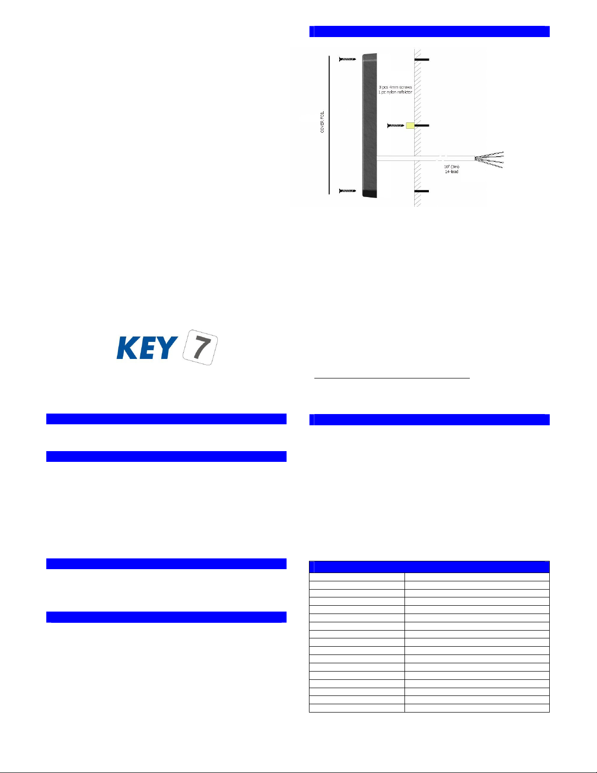
Mounting
SA850 mounts with only 2 screws on flat building surface
DON’T FO GET DIODE ON INDUCTIVE LOADS!!!!
eset to factory settings
Reset to factory settings following below steps:
SA850 is now reset to factory settings and all codes are cleared.
Specifications
Power supply
8V to 24V DC
Current consumption
typical 40mA
Access output
open collector, max 1A,
24V
By
-
pass output
isolated, max100mA, 25 ohm, 50V
Bell output
open collector, max 1A, 24V
Thread alarm output
open collector, max 1A, 24V
Sabotage loop
isolated, max100mA, 25 ohm, 50V
Serial output
RS232, RS485, Wiegand, ABA, KeyLink+
User code memory
100 key codes
By
-
pass time
on/off or 1 to 999 seconds
Access time
on/off or 1 to 999 seconds
Thread alarm time
3 seconds
Wire
10’ (3 m), 14-lead
Dimensions (H-W-D)
0.59in-1.93in-0.59in (150mm-49mm-15mm)
Weight
10.2oz (286g)
Operating temperatures
-30°F to 150°F (-35°C to 65°C)
Operating humidity
0%-100%
All specs are subject to change without prior notice. Latest information is available on www.keyseven.com.
1
Mark the 4 drilling holes with the
drill guide and drill the holes
according to the wall material.
2
Fasten the nylon reflector.
3
Guide the cable trough the hole in
the wall and fasten screws loosely.
SA850
is delivered with 3 meters of flexible
14-core wire:
Red
8
-
24V DC
Back
Ground. 0V
Yellow
Access output. Open collector
-
"Makes a ground" when output is activated.
Green/White
By
-
pass output, wire 1. Isolated output.
Green/Brown
By-pass output, wire 2. Isolated output.
Blue
Sabotage loop, wire 1. Isolated output.
Blue/Red
Sabotage loop, wire 2. Isolated output.
Green
Bell output. Open collector
-
"Makes a ground" when output is activated.
Violet
Thread alarm output. Open collector - "Makes a ground" when output is activated.
Grey/Pink
RS485 data, A
Grey
RS485 data, B
White
Status indicator input. Connects to a central unit that signals its (by
-
pass) state.
Pink
Buzzer. Can be used to externally control the buzzer.
Brown
-
4
Co
nnect SA850 wires appropriate and test tamper circuit with function 42 (
Sabotage
test)
. Tighten screws.
5
Clean key surface. Remove adhesive protection from front cover foil and place it
carefully on the SA850.
1:
Disconnect power supply and network wires
2:
Connect Pink wire (buzzer) to Black wire (ground)
3:
Re-connect power and wait 5 sec until red LED lights up
4:
Release Pink wire (buzzer) from Black wire (ground) within 5
sec.
SA850-A20
INSTALLATIONS MANUAL
Rev. 4.0
•ACCESS CONT OL
•BY-PASS
•STAND ALONE + NETWO K
•SILENT ALA M
•SKAFO cl. 3 approved
SA850-A20 is both access control and by-pass switch with individual outputs.
SA850-A20 isolated by-pass output and 1A open collector access output
SA850-A20 has up to 100 user codes.
SA850-A20 mounts easily on any building surface.
SA850-A20 tools make it easy to configure the unit.
SA850-A20 networks with other SA850’s and PC (supervision/control).
SA850-A20 can be programmed from the keypad or from a PC.
SA850-A20 ‘clickable’ keys, 3 bright LED’s and multi-tone buzzer.
SA850-A20 buzzer and LED’s are externally controllable.
SA850-A20 has a separate output for thread alarm (secret code).
SA850-A20 has a bell button with dedicated output.
SA850-A20 has input for EXIT-button.
SA850-A20 outputs are programmable to work as timer or toggle.
SA850-A20 can be connected to PC or printer for log function.
SA850-A20 has optical sensor for sabotage sensing.
SA850-A20 uses latest FLASH-technology
SA850-A20 is also available with prox reader (SA850-A30).

D ILL GUIDE
5mm
7mm
5mm
5mm
Configuration
SA850 configuration is divided into 16 configurations codes.
Configuration is done by entering below sequence:
P [b or s [yy [z P
P: P-button
b=programcode, s=systemcode (8 digits)
yy: function code
z: configuration data
Configuration codes (yy):
Default values
10: Program code
12345678
30: System code 09876543
31: Code length 4
32: Access profile 111
33: Access time
3
34: By
-
pass function
0
35: By-pass time 30
36: LED/Buzzer function 031313031101
37: Pulse time (LED/Buzzer) 5
38: Lockout time
30
39: Network ID
0
40: Network protocol 0
41: Ext. control signal 0
42: Sabotage test -
43: Alarm function
0
44: Thread alarm code none
Note:
1. Program code can only be used for configuration code 10.
2. Length of z can be 1 to 16 digits
System code must be entered
within 60 minutes
after applying power.
On the following sections the 16 configuration codes are explained …
Try also:
SA850-A30 with built-in proximity reader
easy configuration with our free PC
KeyLink+ PC program
network functions
Having problems? Contact your dealer or visit our
homepage www.keyseven.com.
10: Program code change
P [s or b P 10 [nnnnnnnn [kkkkkkkk P
nnnnnnnn: the new program code
kkkkkkkk: repeated new program code
31: User Code length
P [s P 31 [z P
Length of user code. z can be from 2 to 8 digits.
39: Network ID
P [s P 39 [zzz P
zzz=000-255
Network address when SA850 is part of network with other SA850’s or PC.
30: System code change
P [s P 30 [nnnnnnnn [kkkkkkkk P
nnnnnnnn: the new system code
kkkkkkkk: repeated new system code
32: Access profile
P [s P 32 [abc P
a = AB-codes, not by-passed
b = AB-codes, by-passed
c = A-codes, by-passed
a, b and c values:
0: Pin code
and
Prox, 1: Pin code
or
Prox, 2:
Only
Pin code, 3:
Only
Prox.
33: Access time
P [s P 33 [z P
z=0-999.
Indicates active time in seconds for access output. 0 = on/off toggle function.
34: By-pass function
P [s P 34 [z P
z=0: output not inverted. z=1 output inverted. Add 16 to activate “double-code”
function.
36: LED/Buzzer function
P [s P 36 [aaaabbbbcccc P
aaaa = green, yellow, red, buzzer in normal state
bbbb = green, yellow, red, buzzer in by-pass state
cccc = green, yellow, red, buzzer in access state
a, b and c values:
0: off, 1: on, 2: pulse, 3: externally controlled (white wire – LED / pink –
buzzer), 4: ext. controlled pulse.
37: Pulse time (LED/Buzzer)
P [s P 37 [z P
z=0-999
Indicates LED/buzzer pulse time in 1/10 seconds. See system manual for closer
description.
38: Lockout time
P [s P 38 [z P
z=0-999
Indicates lockout time in seconds after 3 invalid entries. 0 means no lockout.
40: Network protocol
P [s P 40 [z P
z=0-9
Networking protocol.
0: Log, 1: KeyLink+, 2: Wiegand, 3: ABA, 4: I/O extension
41: Ext. control signal (EXIT-button/Buzzer)
P [s P 41 [z P
External input line (pink) can be used as “EXIT-button”:
z=0: No EXIT-function
z=1: EXIT-function
42: Sabotage test
P [s P 42 …( test )... P
Is used to check the optical sabotage circuit during installation. Green LED and
buzzer indicate sabotage when testing. Terminate test by pressing
P
.
43: Alarm function
P [s P 43 [z P
Z=0: Sabotage
Z=1: Sabotage and Thread code
Z=2: Sabotage and code tampering
Z=3: Sabotage, code tampering and Thread code
44: Thread alarm code
P [s P 44 [z P
z: Last digit in normal user code. If activated in ‘Alarm function’ then z is the
value of the last digit that enables the thread alarm (violet wire).
35: By-pass time
P [s P 35 [z P
z=0-999
Indicates active time in seconds for by-pass output. 0 = on/off toggle function.
Other Key 7 Keypad manuals
Popular Keypad manuals by other brands

GTO
GTO Linear PRO ACCESS 10014578-01 Operation instructions

Universal Remote Control
Universal Remote Control Total Control TKP-7000 owner's manual

aikron
aikron A20-3V Operation manual

Melcom
Melcom K6600 installation instructions

DS
DS DS7445 installation instructions

Security Command
Security Command Executive series user guide