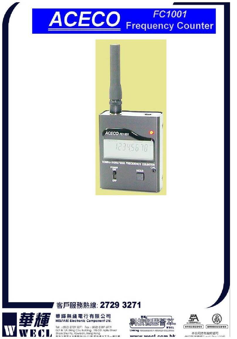
Keysight Technologies 53150A User manual

Keysight 53150A/151A/152A
Microwave Frequency
Counter
This guide describes how to use the Keysight 53150A, 53151A, and
53152A Microwave Frequency Counters. The information in this guide
applies to instruments having the number prefix listed below, unless
accompanied by a “Manual Updating Changes” package indicating
otherwise.
SERIAL PREFIX NUMBER: 3735A, US3925, and US4050 (53150A)
3736A, US3926, and US4051 (53151A)
3737A, US3927, and US4052 (53152A)
Assembly Level
Service Guide
Test Equipment Depot - 800.517.8431 - 99 Washington Street Melrose, MA 02176 - TestEquipmentDepot.com

2 Keysight 53150A/151A/152A Assembly Level Service Guide
Notices
Copyright Notice
© Keysight Technologies 1999 - 2017
No part of this manual may be repro-
duced in any form or by any means
(including electronic storage and
retrieval or translation into a foreign
language) without prior agreement and
written consent from Keysight Technol-
ogies as governed by United States and
international copyright laws.
Manual Part Number
53150-90015
Edition
Edition 3, December 1, 2017
Printed in:
Printed in Malaysia
Published by:
Keysight Technologies
Bayan Lepas Free Industrial Zone,
11900 Penang, Malaysia
Technology Licenses
The hardware and/or software
described in this document are fur-
nished under a license and may be
used or copied only in accordance with
the terms of such license.
Declaration of Conformity
U.S. Government Rights
The Software is “commercial computer
software,” as defined by Federal Acqui-
sition Regulation (“FAR”) 2.101. Pursu-
ant to FAR 12.212 and 27.405-3 and
Department of Defense FAR Supple-
ment (“DFARS”) 227.7202, the U.S.
government acquires commercial com-
puter software under the same terms
by which the software is customarily
provided to the public. Accordingly,
Keysight provides the Software to U.S.
government customers under its stan-
dard commercial license, which is
embodied in its End User License
Agreement (EULA), a copy of which can
be found at http://www.keysight.com/
find/sweula. The license set forth in the
EULA represents the exclusive authority
by which the U.S. government may use,
modify, distribute, or disclose the Soft-
ware. The EULA and the license set
forth therein, does not require or per-
mit, among other things, that Keysight:
(1) Furnish technical information
related to commercial computer soft-
ware or commercial computer software
documentation that is not customarily
provided to the public; or (2) Relinquish
to, or otherwise provide, the govern-
ment rights in excess of these rights
customarily provided to the public to
use, modify, reproduce, release, per-
form, display, or disclose commercial
computer software or commercial com-
puter software documentation. No
additional government requirements
beyond those set forth in the EULA
shall apply, except to the extent that
those terms, rights, or licenses are
explicitly required from all providers of
commercial computer software pursu-
ant to the FAR and the DFARS and are
set forth specifically in writing else-
where in the EULA. Keysight shall be
under no obligation to update, revise or
otherwise modify the Software. With
respect to any technical data as
defined by FAR 2.101, pursuant to FAR
12.211 and 27.404.2 and DFARS
227.7102, the U.S. government
acquires no greater than Limited Rights
as defined in FAR 27.401 or DFAR
227.7103-5 (c), as applicable in any
technical data.
Warranty
THE MATERIAL CONTAINED IN THIS
DOCUMENT IS PROVIDED “AS IS,”
AND IS SUBJECT TO BEING
CHANGED, WITHOUT NOTICE, IN
FUTURE EDITIONS. FURTHER, TO THE
MAXIMUM EXTENT PERMITTED BY
APPLICABLE LAW, KEYSIGHT DIS-
CLAIMS ALL WARRANTIES, EITHER
EXPRESS OR IMPLIED, WITH REGARD
TO THIS MANUAL AND ANY INFORMA-
TION CONTAINED HEREIN, INCLUD-
ING BUT NOT LIMITED TO THE
IMPLIED WARRANTIES OF MER-
CHANTABILITY AND FITNESS FOR A
PARTICULAR PURPOSE. KEYSIGHT
SHALL NOT BE LIABLE FOR ERRORS
OR FOR INCIDENTAL OR CONSE-
QUENTIAL DAMAGES IN CONNECTION
WITH THE FURNISHING, USE, OR
PERFORMANCE OF THIS DOCUMENT
OR OF ANY INFORMATION CON-
TAINED HEREIN. SHOULD KEYSIGHT
AND THE USER HAVE A SEPARATE
WRITTEN AGREEMENT WITH WAR-
RANTY TERMS COVERING THE MATE-
RIAL IN THIS DOCUMENT THAT
CONFLICT WITH THESE TERMS, THE
WARRANTY TERMS IN THE SEPARATE
AGREEMENT SHALL CONTROL.
Safety Information
CAUTION
A CAUTION notice denotes a hazard. It
calls attention to an operating proce-
dure, practice, or the like that, if not
correctly performed or adhered to,
could result in damage to the product
or loss of important data. Do not pro-
ceed beyond a CAUTION notice until
the indicated conditions are fully
understood and met.
WARNING
A WARNING notice denotes a hazard. It
calls attention to an operating proce-
dure, practice, or the like that, if not
correctly performed or adhered to,
could result in personal injury or death.
Do not proceed beyond a WARNING
notice until the indicated conditions are
fully understood and met.

Keysight 53150A/151A/152A Assembly Level Service Guide 3
Safety Symbols
The following symbols on the instrument and in the documentation indicate
precautions which must be taken to maintain safe operation of the instrument.
Caution, risk of danger (refer to this
manual for specific Warning or Caution
information)
Caution, risk of electric shock
Earth (ground) terminal Frame or chassis (ground) terminal
Alternating current (AC) Direct current (DC)

4 Keysight 53150A/151A/152A Assembly Level Service Guide
Detailed Warranty Information
Keysight does not warrant that the operation of Keysight products will be
uninterrupted or error free. If Keysight is unable, within a reasonable time, to
repair or replace any product to a condition as warranted, customer will be
entitled to a refund of the purchase price upon prompt return of the product.
Keysight products may contain remanufactured parts equivalent to new in
performance or may have been subjected to incidental use.
The warranty period begins on the date of delivery or on the date of installation if
installed by Keysight. If customer schedules or delays Keysight installation more
than 30 days after delivery, warranty begins on the 31st day from delivery.
Warranty does not apply to defects resulting from (a) improper or inadequate
maintenance or calibration, (b) software, interfacing, parts or supplies not
supplied by Keysight, (c) unauthorized modification or misuse, (d) operation
outside of the published environmental specifications for the product, or
(e) improper site preparation or maintenance.
TO THE EXTENT ALLOWED BY LOCAL LAW, THE ABOVE WARRANTIES ARE
EXCLUSIVE AND NO OTHER WARRANTY OR CONDITION, WHETHER WRITTEN
OR ORAL, IS EXPRESSED OR IMPLIED AND KEYSIGHT SPECIFICALLY DISCLAIMS
ANY IMPLIED WARRANTIES OR CONDITIONS OF MERCHANTABILITY,
SATISFACTORY QUALITY, AND FITNESS FOR A PARTICULAR PURPOSE.
Keysight will be liable for damage to tangible property per incident up to the
greater of $300,000 or the actual amount paid for the product that is the subject
of the claim, and for damages for bodily injury or death, to the extent that all such
damages are determined by a court of competent jurisdiction to have been
directly caused by a defective Keysight product.
TO THE EXTENT ALLOWED BY LOCAL LAW, THE REMEDIES IN THIS WARRANTY
STATEMENT ARE CUSTOMER’S SOLE AND EXCLUSIVE REMEDIES. EXCEPT AS
INDICATED ABOVE, IN NO EVENT WILL KEYSIGHT OR ITS SUPPLIERS BE LIABLE
FOR LOSS OF DATA OR FOR DIRECT, SPECIAL, INCIDENTAL, CONSEQUENTIAL
(INCLUDING LOST PROFIT OR DATA), OR OTHER DAMAGE, WHETHER BASED IN
CONTRACT, TORT, OR OTHERWISE.
For consumer transactions in Australia and New Zealand: the warranty terms
contained in this statement, except to the extent lawfully permitted, do not
exclude, restrict or modify and are in addition to the mandatory statutory rights
applicable to the sale of this product to you.

Keysight 53150A/151A/152A Assembly Level Service Guide 5
Safety Considerations
Read the information below before using this instrument.
The following general safety precautions must be observed during all phases of
operation, service, and repair of this instrument. Failure to comply with these
precautions or with specific warnings elsewhere in this manual violates safety
standards for design, manufacture, and intended use of the instrument. Keysight
Technologies assumes no liability for the customer’s failure to comply with these
requirements.
Whenever it is likely that the protection has been impaired, the instrument must
be made inoperative and be secured against any unintended operation.
If this instrument is to be energized via an autotransformer (for voltage reduction),
make sure the common terminal is connected to the earthed pole terminal
(neutral) of the power source.
Instructions for adjustments while covers are removed and for servicing are for use
by trained personnel only. To avoid dangerous electric shock, do not perform such
adjustments or servicing unless qualified to do so.
For continued protection against fire, replace the line fuse(s) with fuses of the
same current rating and type (for example, normal blow, time delay). Do not use
repaired fuses or short-circuited fuseholders.
WARNING
INSTRUCTIONS FOR ADJUSTMENTS WHILE COVERS ARE REMOVED AND
FOR SERVICING ARE FOR USE BY SERVICE-TRAINED PERSONNEL ONLY. TO
AVOID DANGEROUS ELECTRIC SHOCK, DO NOT PERFORM SUCH
ADJUSTMENTS OR SERVICING UNLESS QUALIFIED TO DO SO.
WARNING
ANY INTERRUPTION OF THE PROTECTIVE GROUNDING CONDUCTOR
(INSIDE OR OUTSIDE THE PRODUCT’S CIRCUITRY) OR DISCONNECTING
THE PROTECTIVE EARTH TERMINAL WILL CAUSE A POTENTIAL SHOCK
HAZARD THAT COULD RESULT IN PERSONAL INJURY. (GROUNDING ONE
CONDUCTOR OF A TWO CONDUCTOR OUTLET IS NOT SUFFICIENT
PROTECTION.)

6 Keysight 53150A/151A/152A Assembly Level Service Guide
Safety Earth Ground
An uninterruptible safety earth ground must be maintained from the mains power
source to the product’s ground circuitry.
Acoustic Noise Emissions
LpA<47 dB at operator position, at normal operation, tested per EN 27779. All
data are the results from type test.
Geräuschemission
LpA<47 dB am Arbeits platz, normaler Betrieb, geprüft nach EN 27779. Die
Angagen beruhen auf Ergebnissen von Typenprüfungen.
Electrostatic Discharge Immunity Testing
When the product is tested with 8kV AD, 4kV CD and 4kV ID according to
IEC801-2, a system error may occur that may affect measurement data made
during these disturbances. After these occurrences, the system self-recovers
without user intervention.
WARNING
WHEN MEASURING POWER LINE SIGNALS, BE EXTREMELY CAREFUL AND
ALWAYS USE A STEP-DOWN ISOLATION TRANSFORMER WHICH OUTPUT IS
COMPATIBLE WITH THE INPUT MEASUREMENT CAPABILITIES OF THIS
PRODUCT. THIS PRODUCT’S FRONT AND REAR PANELS ARE TYPCIALLY AT
EARTH GROUND. THUS, NEVER TRY TO MEASURE AC POWER LINE
SIGNALS WITHOUT AN ISOLATION TRANSFORMER.

Keysight 53150A/151A/152A Assembly Level Service Guide 7
Waste Electrical and Electronic Equipment (WEEE) Directive
This instrument complies with the WEEE Directive marking requirement. This
affixed product label indicates that you must not discard this electrical or
electronic product in domestic household waste.
Product category:
With reference to the equipment types in the WEEE directive Annex 1, this
instrument is classified as a “Monitoring and Control Instrument” product.
The affixed product label is as shown below.
Do not dispose in domestic household waste.

8 Keysight 53150A/151A/152A Assembly Level Service Guide
THIS PAGE HAS BEEN INTENTIONALLY LEFT BLANK.

Keysight 53150A/151A/152A Assembly Level Service Guide 9
Table of Contents
Safety Symbols . . . . . . . . . . . . . . . . . . . . . . . . . . . . . . . . . . . . . . . . . . . . .3
Detailed Warranty Information . . . . . . . . . . . . . . . . . . . . . . . . . . . . . . . . .4
Safety Considerations . . . . . . . . . . . . . . . . . . . . . . . . . . . . . . . . . . . . . . . .5
Safety Earth Ground . . . . . . . . . . . . . . . . . . . . . . . . . . . . . . . . . . . . . . . . .6
Acoustic Noise Emissions . . . . . . . . . . . . . . . . . . . . . . . . . . . . . . . . . . . . .6
Geräuschemission . . . . . . . . . . . . . . . . . . . . . . . . . . . . . . . . . . . . . . . . . . .6
Electrostatic Discharge Immunity Testing . . . . . . . . . . . . . . . . . . . . . . . .6
Waste Electrical and Electronic Equipment (WEEE) Directive . . . . . . . .7
Product category: . . . . . . . . . . . . . . . . . . . . . . . . . . . . . . . . . . . . . . . .7
Sales and Technical Support . . . . . . . . . . . . . . . . . . . . . . . . . . . . . . . . . .7
List of Figures . . . . . . . . . . . . . . . . . . . . . . . . . . . . . . . . . . . . . . . . . . . . .13
List of Tables . . . . . . . . . . . . . . . . . . . . . . . . . . . . . . . . . . . . . . . . . . . . . .15
In This Guide
How to Use This Guide . . . . . . . . . . . . . . . . . . . . . . . . . . . . . . . . . . . . . .18
Repair Strategy . . . . . . . . . . . . . . . . . . . . . . . . . . . . . . . . . . . . . . . . .18
Instrument Identification . . . . . . . . . . . . . . . . . . . . . . . . . . . . . . . . . .19
Instruments Covered by this Guide . . . . . . . . . . . . . . . . . . . . . . . . . .19
Assembly-Level Service Guide Organization . . . . . . . . . . . . . . . . . .19
How to Order Guides . . . . . . . . . . . . . . . . . . . . . . . . . . . . . . . . . . . . .20
Description of the Microwave Frequency Counter . . . . . . . . . . . . . . . .21
Options . . . . . . . . . . . . . . . . . . . . . . . . . . . . . . . . . . . . . . . . . . . . . . . . . .22
Hardware . . . . . . . . . . . . . . . . . . . . . . . . . . . . . . . . . . . . . . . . . . . . . .22
Support . . . . . . . . . . . . . . . . . . . . . . . . . . . . . . . . . . . . . . . . . . . . . . .22
Accessories Supplied and Available . . . . . . . . . . . . . . . . . . . . . . . . . . . .23
Accessories Supplied . . . . . . . . . . . . . . . . . . . . . . . . . . . . . . . . . . . . .23
Accessories Available . . . . . . . . . . . . . . . . . . . . . . . . . . . . . . . . . . . . .23
Manuals Supplied . . . . . . . . . . . . . . . . . . . . . . . . . . . . . . . . . . . . . . .23
1 Performance Tests - Verifying Specifications

10 Keysight 53150A/151A/152A Assembly Level Service Guide
Introduction . . . . . . . . . . . . . . . . . . . . . . . . . . . . . . . . . . . . . . . . . . . . . . 26
Operational Verification . . . . . . . . . . . . . . . . . . . . . . . . . . . . . . . . . . . 26
Complete Performance Tests . . . . . . . . . . . . . . . . . . . . . . . . . . . . . . 27
Recommended Calibration Cycle . . . . . . . . . . . . . . . . . . . . . . . . . . . 27
Test Record . . . . . . . . . . . . . . . . . . . . . . . . . . . . . . . . . . . . . . . . . . . . 27
Equipment Required . . . . . . . . . . . . . . . . . . . . . . . . . . . . . . . . . . . . . . . 28
Operational Verification . . . . . . . . . . . . . . . . . . . . . . . . . . . . . . . . . . . . . 29
Power-On Self Tests . . . . . . . . . . . . . . . . . . . . . . . . . . . . . . . . . . . . . 29
10 MHz Test . . . . . . . . . . . . . . . . . . . . . . . . . . . . . . . . . . . . . . . . . . . . 30
Run Self Test . . . . . . . . . . . . . . . . . . . . . . . . . . . . . . . . . . . . . . . . . . . 31
External Timebase Test . . . . . . . . . . . . . . . . . . . . . . . . . . . . . . . . . . . 32
10 MHz External Timebase Input Test . . . . . . . . . . . . . . . . . . . . . . . 32
Complete Performance Tests . . . . . . . . . . . . . . . . . . . . . . . . . . . . . . . . . 35
Test 1: External Timebase Input Test . . . . . . . . . . . . . . . . . . . . . . . . . . . 36
1 MHz External Timebase Input Test . . . . . . . . . . . . . . . . . . . . . . . . 36
2 MHz External Timebase Input Test . . . . . . . . . . . . . . . . . . . . . . . . 38
5 MHz External Timebase Input Test . . . . . . . . . . . . . . . . . . . . . . . . 38
10 MHz External Timebase Input Test . . . . . . . . . . . . . . . . . . . . . . . 39
Test 2: Channel 1 Frequency Sensitivity . . . . . . . . . . . . . . . . . . . . . . . . 40
Test 2a: 10 Hz to 20 MHz Frequency Sensitivity . . . . . . . . . . . . . . . 40
Test 2b: 50 MHz to 125 MHz Frequency Sensitivity . . . . . . . . . . . . . 42
Test 3: Channel 2 Frequency Sensitivity . . . . . . . . . . . . . . . . . . . . . . . . 45
Test 3a: 50 MHz to 20 GHz Frequency Sensitivity . . . . . . . . . . . . . . 45
Test 3b: 22 GHz to 26.5 GHz Frequency Sensitivity . . . . . . . . . . . . . 47
Test 3c: 30 GHz to 46 GHz Frequency Sensitivity . . . . . . . . . . . . . . 48
Test 4: Channel 2 Power Measurement . . . . . . . . . . . . . . . . . . . . . . . . . 49
Test 4a: 50 MHz to 20 GHz Power Measurement (–20 dBm) . . . . . 49
Test 4b: Channel 2 22 GHz to 26.5 GHz Power Measurement
(–20 dBm) . . . . . . . . . . . . . . . . . . . . . . . . . . . . . . . . . . . . . . . . . . . 51
Test 4c: Channel 2 26.5 GHz to 46 GHz Power Measurement
(–20 dBm) . . . . . . . . . . . . . . . . . . . . . . . . . . . . . . . . . . . . . . . . . . . 52
Test 4d: Channel 2 50 MHz to 20 GHz Power Measurement
(0 dBm) . . . . . . . . . . . . . . . . . . . . . . . . . . . . . . . . . . . . . . . . . . . . . 52
Test 4e: Channel 2 22 GHz to 26.5 GHz Power Measurement

Keysight 53150A/151A/152A Assembly Level Service Guide 11
(0 dBm) . . . . . . . . . . . . . . . . . . . . . . . . . . . . . . . . . . . . . . . . . . . . .53
Test 4f: Channel 2 30 GHz to 46 GHz Power Measurement
(0 dBm) . . . . . . . . . . . . . . . . . . . . . . . . . . . . . . . . . . . . . . . . . . . . .53
Performance Test Record (Page 1 of 4) . . . . . . . . . . . . . . . . . . . . . . . . .54
Performance Test Record (Page 2 of 4) . . . . . . . . . . . . . . . . . . . . . . . . .55
Performance Test Record (Page 3 of 4) . . . . . . . . . . . . . . . . . . . . . . . . .56
Performance Test Record (Page 4 of 4) . . . . . . . . . . . . . . . . . . . . . . . . .57
2Service
Introduction . . . . . . . . . . . . . . . . . . . . . . . . . . . . . . . . . . . . . . . . . . . . . .60
Returning the Counter to Keysight Technologies for Service . . . . . . . .61
Providing Repair Information . . . . . . . . . . . . . . . . . . . . . . . . . . . . . . .61
Packing the Counter in the Original Packaging Materials . . . . . . . .62
Packing the Counter in Commercially Available Packaging
Materials . . . . . . . . . . . . . . . . . . . . . . . . . . . . . . . . . . . . . . . . . . . .62
Calibration Procedure . . . . . . . . . . . . . . . . . . . . . . . . . . . . . . . . . . . . . . .63
Equipment Required . . . . . . . . . . . . . . . . . . . . . . . . . . . . . . . . . . . . .63
Pre-Troubleshooting Information . . . . . . . . . . . . . . . . . . . . . . . . . . . . . .65
Safety Considerations . . . . . . . . . . . . . . . . . . . . . . . . . . . . . . . . . . . .65
Recommended Test Equipment . . . . . . . . . . . . . . . . . . . . . . . . . . . .66
Repair Considerations . . . . . . . . . . . . . . . . . . . . . . . . . . . . . . . . . . . .66
After Service Considerations . . . . . . . . . . . . . . . . . . . . . . . . . . . . . . .67
Assembly Identification and Location . . . . . . . . . . . . . . . . . . . . . . . .68
Troubleshooting the Counter . . . . . . . . . . . . . . . . . . . . . . . . . . . . . . . . .70
Power Supply Check . . . . . . . . . . . . . . . . . . . . . . . . . . . . . . . . . . . . .70
Self-Test . . . . . . . . . . . . . . . . . . . . . . . . . . . . . . . . . . . . . . . . . . . . . . .72
3 Replacing Assemblies - Disassembly and Reassembly
Introduction . . . . . . . . . . . . . . . . . . . . . . . . . . . . . . . . . . . . . . . . . . . . . .78
Tools Required . . . . . . . . . . . . . . . . . . . . . . . . . . . . . . . . . . . . . . . . . . . .79
Do This First . . . . . . . . . . . . . . . . . . . . . . . . . . . . . . . . . . . . . . . . . . . . . .79
Removing the Bumpers . . . . . . . . . . . . . . . . . . . . . . . . . . . . . . . . . . . . .80
Removing the Handle and Handle Mounts . . . . . . . . . . . . . . . . . . . . . .81

12 Keysight 53150A/151A/152A Assembly Level Service Guide
Removing the Rear Bezel . . . . . . . . . . . . . . . . . . . . . . . . . . . . . . . . . . . . 82
Removing the Shroud . . . . . . . . . . . . . . . . . . . . . . . . . . . . . . . . . . . . . . 84
Removing the Front Bezel . . . . . . . . . . . . . . . . . . . . . . . . . . . . . . . . . . . 87
Removing the Rear Panel Assembly . . . . . . . . . . . . . . . . . . . . . . . . . . . 88
Removing the Cooling Fan . . . . . . . . . . . . . . . . . . . . . . . . . . . . . . . . . . . 91
Replacing the Power Supply . . . . . . . . . . . . . . . . . . . . . . . . . . . . . . . . . 92
4ReplaceableParts
Introduction . . . . . . . . . . . . . . . . . . . . . . . . . . . . . . . . . . . . . . . . . . . . . . 96
Replaceable Parts . . . . . . . . . . . . . . . . . . . . . . . . . . . . . . . . . . . . . . . . . 97
How To Order A Part . . . . . . . . . . . . . . . . . . . . . . . . . . . . . . . . . . . . . . . 98
Contacting Keysight Technologies . . . . . . . . . . . . . . . . . . . . . . . . . . 99
Parts Identification . . . . . . . . . . . . . . . . . . . . . . . . . . . . . . . . . . . . . . . . 100
Reference Designations . . . . . . . . . . . . . . . . . . . . . . . . . . . . . . . . . 100
Cabinet Parts and Hardware . . . . . . . . . . . . . . . . . . . . . . . . . . . . . . 100
Accessories and Miscellaneous Items . . . . . . . . . . . . . . . . . . . . . . 100
5Backdating
Introduction . . . . . . . . . . . . . . . . . . . . . . . . . . . . . . . . . . . . . . . . . . . . . 108
6Specifications
Index . . . . . . . . . . . . . . . . . . . . . . . . . . . . . . . . . . . . . . . . . . . . . . . . . . . 111

Keysight 53150A/151A/152A Assembly Level Service Guide 13
List of Figures
Figure 1-1 External Timebase Test Setup . . . . . . . . . . . . . . . . . . .33
Figure 1-2 External Timebase Test Setup . . . . . . . . . . . . . . . . . . .37
Figure 1-3 10 Hz to 20 MHz Frequency Sensitivity Test Setup . .41
Figure 1-4 50 MHz to 125 MHz Frequency Sensitivity Test
Setup . . . . . . . . . . . . . . . . . . . . . . . . . . . . . . . . . . . .42
Figure 1-5 50 MHz to 20 GHz Frequency Sensitivity Test
Setup . . . . . . . . . . . . . . . . . . . . . . . . . . . . . . . . . . . .46
Figure 1-6 50 MHz to 20 GHz (–20 dBm) Power Measurement
Test Setup . . . . . . . . . . . . . . . . . . . . . . . . . . . . . . . .50
Figure 2-1 Calibrating the Counter . . . . . . . . . . . . . . . . . . . . . . . .63
Figure 2-3 A4 DC Power Supply Test-Point Locations . . . . . . . . .70
Figure 4-1 Keysight 53150A/151A/152A Exploded View —
Internal Parts . . . . . . . . . . . . . . . . . . . . . . . . . . . . .101
Figure 4-2 Keysight 53150A/151A/152A Exploded View —
Cabinet and External Parts . . . . . . . . . . . . . . . . . .102
Figure 4-3 Keysight 53150A/151A/152A Top View . . . . . . . . . .103

14 Keysight 53150A/151A/152A Assembly Level Service Guide
THIS PAGE HAS BEEN INTENTIONALLY LEFT BLANK.

Keysight 53150A/151A/152A Assembly Level Service Guide 15
List of Tables
Table 1-1 Recommended Test Equipment and Accessories . . . .28
Table 1-2 Complete Performance Tests . . . . . . . . . . . . . . . . . . . .35
Table 2-1 Keysight 53150A/151A/152A Assembly
Identification . . . . . . . . . . . . . . . . . . . . . . . . . . . . . .68
Table 2-2 A4 Power Supply Inputs and Outputs . . . . . . . . . . . . .71
Table 2-3 Self-Test Messages . . . . . . . . . . . . . . . . . . . . . . . . . . .73
Table 2-4 Front Panel Display Error Messages . . . . . . . . . . . . . .74
Table 2-5 RS-232 Error Messages . . . . . . . . . . . . . . . . . . . . . . . .75
Table 4-1 Reference Designations . . . . . . . . . . . . . . . . . . . . . . .100
Table 4-2 Keysight 53150A/151A/152A Replaceable Parts . . .104
Table 4-3 Keysight 53150A/151A/152A Accessories and
Miscellaneous Items . . . . . . . . . . . . . . . . . . . . . . .106

16 Keysight 53150A/151A/152A Assembly Level Service Guide
THIS PAGE HAS BEEN INTENTIONALLY LEFT BLANK.

Keysight 53150A/151A/152A Microwave Frequency Counter
Assembly Level Service Guide
17
In This Guide
How to Use This Guide 18
Description of the Microwave Frequency Counter 21
Options 22
Accessories Supplied and Available 23
This guide provides assembly-level service information for the Keysight 53150A,
53151A, and 53152A Counters.

In This Guide
18 Keysight 53150A/151A/152A Assembly Level Service Guide
How to Use This Guide
Repair Strategy
This service guide is designed to isolate failures to the assembly level only.
The Keysight 53150A/151A/152A Counter can be returned to Keysight for all
service work, including troubleshooting, and verifying specifications. Contact your
nearest Keysight Sales and Service Office for more details.
If you decide to service the Counter yourself, use the troubleshooting procedures
in Chapter 2 (Service) and the disassembly and reassembly procedures in
Chapter 3 (Replacing Assemblies - Disassembly and Reassembly). Then, use the
calibration instructions in Chapter 2 to calibrate the Counter for
peak-performance operation, and finally, perform all of the performance tests in
Chapter 1 to verify that the Counter is operating to the specifications.
NOTE
ISD (Instrument Service Division) Emergency Response or Express Calibration
Service is available for Keysight customers in the USA. If downtime is critical,
you can receive your repaired Counter via overnight shipment. Call
1-800-403-0801, and ask for Emergency Response or Express Calibration
Service. When your Counter is repaired, it is returned via overnight shipment at
no extra charge.
NOTE
If the motherboard, the sampler, or the front-panel assembly are defective, the
instrument must be returned to an Keysight Service Center for repair and
recalibration.

In This Guide
Keysight 53150A/151A/152A Assembly Level Service Guide 19
Instrument Identification
The instrument is identified by the serial number on the rear panel. Keysight uses
a two-part serial number with the first part (prefix) identifying a series of
instruments and the second part (suffix) identifying a particular instrument within
a series. Keysight-assigned alpha characters before the prefix identify the country
in which the instrument was manufactured.
Instruments Covered by this Guide
This guide applies directly to Keysight 53150A, 53151A, and 53152A Counters
that have the same serial number prefix(es) shown on the title page. If the serial
number prefix of your Counter differs from that listed on the title page of this
guide, there may be differences between this guide and your instrument.
Instruments having a higher serial prefix are covered (when required) by one or
more manual-change sheets included with this guide. If a required change sheet
is missing, contact your nearest Keysight Sales Office listed at the back of this
guide.
Assembly-Level Service Guide Organization
This Assembly-Level Service Guide consists of a table of contents, a preface, six
chapters, and an index. The page headers identify the chapters and sections of
this manual. The chapter contents are summarized as follows:
Chapter 1, “Performance Tests - Verifying Specifications”provides procedures
that verify the Counter operates properly and meets the Keysight 53150A/151A/
152A specifications given in Chapter 6, “Specifications” in this guide.
Chapter 2, “Service” is divided into seven main sections that provide instructions
for returning the Counter to Keysight for service, calibrating the Counter, and
troubleshooting the assemblies in the Counter.
Chapter 3, “Replacing Assemblies - Disassembly and Reassembly” provides
procedures for replacing defective assemblies and/or modules in the Counter.

In This Guide
20 Keysight 53150A/151A/152A Assembly Level Service Guide
Chapter 4, “Replaceable Parts”lists the replaceable parts contained in the
Counter, and explains how to order replacement parts for your Counter.
Chapter 5, “Backdating” contains information required to adapt this manual for
older instruments (to be provided when required).
Chapter 6, “Specifications” lists all the specifications and operating
characteristics for the Keysight 53150A/151A/152A Counter.
How to Order Guides
The part number for this guide is listed on the Certification and Warranty page
(page 4) and on the back cover of this guide.
Other manuals for 53150A
1
This manual suits for next models
2
Table of contents
Other Keysight Technologies Cash Counter manuals

Keysight Technologies
Keysight Technologies 53150A User manual
Keysight Technologies
Keysight Technologies E1420B User manual
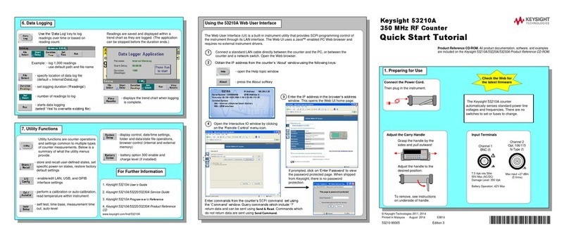
Keysight Technologies
Keysight Technologies 53210A User manual
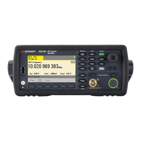
Keysight Technologies
Keysight Technologies 53210A User manual
Keysight Technologies
Keysight Technologies VXI bus 75000 C Series User manual
