Keysight Technologies M9035A User guide

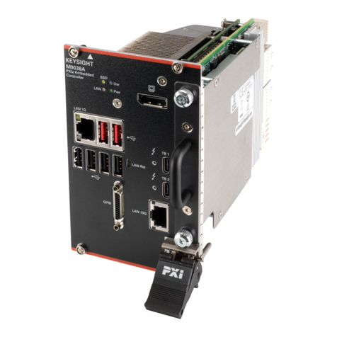
Keysight M9035A PXIe
Embedded Controller
Startup Guide


iii
Notices
© Keysight Technologies, Inc. 2021
No part of this manual may be repro-
duced in any form or by any means
(including electronic storage and retrieval
or translation into a foreign language)
without prior agreement and written con-
sent from Keysight Technologies, Inc. as
governed by United States and interna-
tional copyright laws.
Manual Part Number
M9035-90001
Edition
First Edition, September 2021
Published in USA
Keysight Technologies, Inc.
1400 Fountaingrove Parkway
Santa Rosa, CA 95403 USA
Trademarks
AXIe is a registered trademark of the AXIe
Consortium.
PXI is a registered trademark of the PXI
Systems Alliance.
PICMG®, Compact PCI®, and
AdvancedTCA® are registered trade-
marks of the PCI Industrial Computer
Manufacturers Group.
PCI-SIG®, PCI Express®, and PCIe® are
registered trademarks of PCI-SIG.
Sales and Technical Support
To contact Keysight for sales and techni-
cal support, refer to the support links on
the following Keysight websites:
www.keysight.com/find/M9035A (prod-
uct-specific information and support,
software and documentation updates)
www.keysight.com/find/assist (world-
wide contact information for repair and
service)
Declaration of Conformity
Declarations of Conformity for this prod-
uct and for other Keysight products may
be downloaded from the Web. Go to
http://www.keysight.com/go/conformity
and click on “Declarations of Conformity.”
You can then search by product number
to find the latest Declaration of Confor-
mity.
Technology Licenses
The hardware and/or software described
in this document are furnished under a
license and may be used or copied only in
accordance with the terms of such
license.
Warranty
THE MATERIAL CONTAINED IN THIS
DOCUMENT IS PROVIDED “AS IS,” AND
IS SUBJECT TO BEING CHANGED,
WITHOUT NOTICE, IN FUTURE EDI-
TIONS. FURTHER, TO THE MAXIMUM
EXTENT PERMITTED BY APPLICABLE
LAW, KEYSIGHT DISCLAIMS ALL WAR-
RANTIES, EITHER EXPRESS OR IMPLIED,
WITH REGARD TO THIS MANUAL AND
ANY INFORMATION CONTAINED
HEREIN, INCLUDING BUT NOT LIMITED
TO THE IMPLIED WARRANTIES OF MER-
CHANTABILITY AND FITNESS FOR A
PARTICULAR PURPOSE. KEYSIGHT
SHALL NOT BE LIABLE FOR ERRORS OR
FOR INCIDENTAL OR CONSEQUENTIAL
DAMAGES IN CONNECTION WITH THE
FURNISHING, USE, OR PERFORMANCE
OF THIS DOCUMENT OR OF ANY INFOR-
MATION CONTAINED HEREIN. SHOULD
KEYSIGHT AND THE USER HAVE A SEP-
ARATE WRITTEN AGREEMENT WITH
WARRANTY TERMS COVERING THE
MATERIAL IN THIS DOCUMENT THAT
CONFLICT WITH THESE TERMS, THE
WARRANTY TERMS IN THE SEPARATE
AGREEMENT SHALL CONTROL.
Keysight Technologies does not warrant
third-party system-level (combination of
chassis, controllers, modules, etc.) per-
formance, safety, or regulatory compli-
ance unless specifically stated.
DFARS/Restricted Rights
Notices
If software is for use in the performance
of a U.S. Government prime contract or
subcontract, Software is delivered and
licensed as “Commercial computer soft-
ware” as defined in DFAR 252.227-7014
(June 1995), or as a “commercial item” as
defined in FAR 2.101(a) or as “Restricted
computer software” as defined in FAR
52.227-19 (June 1987) or any equivalent
agency regulation or contract clause.
Use, duplication or disclosure of Software
is subject to Keysight Technologies’ stan-
dard commercial license terms, and non-
DOD Departments and Agencies of the
U.S. Government will receive no greater
than Restricted Rights as defined in FAR
52.227-19(c)(1-2) (June 1987). U.S. Gov-
ernment users will receive no greater
than Limited Rights as defined in FAR
52.227-14 (June 1987) or DFAR 252.227-
7015 (b)(2) (November 1995), as applica-
ble in any technical data.

Safety Information
The following general safety precau-
tions must be observed during all
phases of operation of this instrument.
Failure to comply with these precau-
tions or with specific warnings or oper-
ating instructions in the product
manuals violates safety standards of
design, manufacture, and intended use
of the instrument. Keysight Technolo-
gies assumes no liability for the cus-
tomer's failure to comply with these
requirements.
General
This product has been designed and
tested in accordance with accepted
industry standards and has been sup-
plied in a safe condition. The docu-
mentation contains information and
warnings that must be followed by the
user to ensure safe operation and to
maintain the product in a safe condi-
tion.
Before Applying Power
Verify that all safety precautions are
taken. Make all connections to the unit
before applying power. Note the exter-
nal markings described under “Safety
Symbols”.
Ground the Instrument
Keysight chassis’ are provided with a
grounding-type power plug. The
instrument chassis and cover must be
connected to an electrical ground to
minimize shock hazard. The ground pin
must be firmly connected to an electri-
cal ground (safety ground) terminal at
the power outlet. Any interruption of
the protective (grounding) conductor
or disconnection of the protective
earth terminal will cause a potential
shock hazard that could result in per-
sonal injury.
Do Not Operate in an Explosive
Atmosphere
Do not operate the module/chassis in
the presence of flammable gases or
fumes.
Do Not Operate Near Flammable
Liquids
Do not operate the module/chassis in
the presence of flammable liquids or
near containers of such liquids.
Cleaning
To prevent electrical shock, disconnect
the instrument from mains before
cleaning. Use a dry cloth or one
slightly dampened with water to clean
the external case parts. Do not attempt
to clean internally.
Do Not Remove Instrument Cover
Only qualified, service-trained person-
nel who are aware of the hazards
involved should remove instrument
covers. Always disconnect the power
cable and any external circuits before
removing the instrument cover.
Keep away from live circuits
Operating personnel must not remove
equipment covers or shields. Proce-
dures involving the removal of covers
and shields are for use by service-
trained personnel only. Under certain
conditions, dangerous voltages may
exist even with the equipment
switched off. To avoid dangerous elec-
trical shock, DO NOT perform proce-
dures involving cover or shield removal
unless you are qualified to do so.
DO NOT operate damaged
equipment
Whenever it is possible that the safety
protection features built into this prod-
uct have been impaired, either through
physical damage, excessive moisture,
or any other reason, REMOVE POWER
and do not use the product until safe
operation can be verified by service-
trained personnel. If necessary, return
the product to an Keysight Technolo-
gies Sales and Service Office for ser-
vice and repair to ensure the safety
features are maintained.
DO NOT block the primary
disconnect
The primary disconnect device is the
appliance connector/power cord when
a chassis used by itself, but when
installed into a rack or system the dis-
connect may be impaired and must be
considered part of the installation.
Do Not Modify the Instrument
Do not install substitute parts or per-
form any unauthorized modification to
the product. Return the product to an
Keysight Sales and Service Office to
ensure that safety features are main-
tained.
In Case of Damage
Instruments that appear damaged or
defective should be made inoperative
and secured against unintended oper-
ation until they can be repaired by
qualified service personnel
Do NOT block vents and fan exhaust:
To ensure adequate cooling and venti-
lation, leave a gap of at least 50mm
(2") around vent holes on both sides of
the chassis.
Do NOT operate with empty slots: To
ensure proper cooling and avoid dam-
aging equipment, fill each empty slot
with an AXIe filler panel module.
Do NOT stack free-standing chassis:
Stacked chassis should be rack-
mounted.
All modules are grounded through the
chassis: During installation, tighten
each module's retaining screws to
secure the module to the chassis and
to make the ground connection.
Operator is responsible to maintain
safe operating conditions. To ensure
safe operating conditions, modules
should not be operated beyond the full
temperature range specified in the
Environmental and physical specifica-
tion. Exceeding safe operating condi-
tions can result in shorter lifespan,
improper module performance and
user safety issues. When the modules
are in use and operation within the
specified full temperature range is not
maintained, module surface tempera-
tures may exceed safe handling condi-
tions which can cause discomfort or
burns if touched. In the event of a
module exceeding the full temperature
range, always allow the module to cool
before touching or removing modules
from the chassis.
iv

Safety and Regulatory Symbols
A CAUTION denotes a hazard. It
calls attention to an operating pro-
cedure or practice, that, if not cor-
rectly performed or adhered to
could result in damage to the
product or loss of important data.
Do not proceed beyond a CAUTION
notice until the indicated condi-
tions are fully understood and met.
A WARNING denotes a hazard. It
calls attention to an operating pro-
cedure or practice, that, if not cor-
rectly performed or adhered to,
could result in personal injury or
death. Do not proceed beyond a
WARNING notice until the indi-
cated conditions are fully under-
stood and met.
Products may display the following
symbols:
The CSA mark is a registered trade-
mark of the Canadian Standards Asso-
ciation and indicates compliance to
the standards laid out by them. Refer
to the product Declaration of Confor-
mity for details.
Notice for European Community: This
product complies with the relevant
European legal Directives: EMC Direc-
tive and Low Voltage Directive .
The Regulatory Compliance Mark
(RCM) mark is a registered trademark.
This signifies compliance with the Aus-
tralia EMC Framework regulations
under the terms of the Radio Commu-
nication Act of 1992.
ICES/NMB-001 indicates that this ISM
device complies with the Canadian
ICES-001.
Cet appareil ISM est conforme a la
norme NMB-001 du Canada.
This symbol represents the time period
during which no hazardous or toxic
substance elements are expected to
leak or deteriorate during normal use.
Forty years is the expected useful life
of this product.
The UK conformity mark is a UK gov-
ernment owned mark. Products show-
ing this mark comply with all
applicable UK regulations.
South Korean Class A EMC Declara-
tion. this equipment is Class A suitable
for professional use and is for use in
electromagnetic environments outside
of the home.
Waste Electrical and
Electronic
Equipment (WEEE)
Directive
2002/96/EC
This product complies with the WEEE
Directive (2002/96/EC) marking
requirement. The affixed product label
(see below) indicates that you must not
discard this electrical/electronic prod-
uct in domestic household waste.
Product Category: With reference to
the equipment types in the WEEE
directive Annex 1, this product is clas-
sified as a “Monitoring and Control
instrumentation” product.
Do not dispose in domestic household
waste.
To return unwanted products, contact
your local Keysight office for more
information.
Warning, risk of electric
shock
Refer to manual for addi-
tional safety information.
Earth Ground.
Chassis Ground.
Alternating Current (AC).
Standby Power. Unit is not
completely disconnected
from AC mains when
switch is in standby.
Antistatic precautions
should be taken.
CAT I
CAT II
CAT III
CAT IV
IEC Measurement Cate-
gory I, II, III, or IV
For localized Safety Warnings, Refer
to Keysight Safety document (p/n
9320-6792).
M9035A
MSIP-REM-Kst-xxxxx
v

vi

Keysight M9035A PXIe Embedded Controller Startup Guide vii
Contents
Introduction . . . . . . . . . . . . . . . . . . . . . . . . . . . . . . . . . . . . . . . . . . . . . . . . . . . . . 9
Related Documentation . . . . . . . . . . . . . . . . . . . . . . . . . . . . . . . . . . . . . . . . . 9
M9035A at a Glance . . . . . . . . . . . . . . . . . . . . . . . . . . . . . . . . . . . . . . . . . . . . . 10
Front Panel LED Indicators. . . . . . . . . . . . . . . . . . . . . . . . . . . . . . . . . . . . . . 11
Step 1: Unpack and Inspect the Module . . . . . . . . . . . . . . . . . . . . . . . . . . . . . 12
ESD . . . . . . . . . . . . . . . . . . . . . . . . . . . . . . . . . . . . . . . . . . . . . . . . . . . . . . . . 12
Inspect for Damage . . . . . . . . . . . . . . . . . . . . . . . . . . . . . . . . . . . . . . . . . . . 12
If you need to return the module for service . . . . . . . . . . . . . . . . . . . . . . . . 13
Step 2: Verify Shipment Contents. . . . . . . . . . . . . . . . . . . . . . . . . . . . . . . . . . . 14
Step 3: Install the M9035A Embedded Controller . . . . . . . . . . . . . . . . . . . . . . 15
Removing the M9035A from the Chassis. . . . . . . . . . . . . . . . . . . . . . . . . . . 17
Power On Sequence . . . . . . . . . . . . . . . . . . . . . . . . . . . . . . . . . . . . . . . . . . . 17
Power Off Sequence . . . . . . . . . . . . . . . . . . . . . . . . . . . . . . . . . . . . . . . . . . . 17
Power Down Modes . . . . . . . . . . . . . . . . . . . . . . . . . . . . . . . . . . . . . . . . . . . 18
Controller and Chassis Drivers . . . . . . . . . . . . . . . . . . . . . . . . . . . . . . . . . . . 18
Step 4: Review Windows Configuration . . . . . . . . . . . . . . . . . . . . . . . . . . . . . . 19
Windows OS Versions. . . . . . . . . . . . . . . . . . . . . . . . . . . . . . . . . . . . . . . . . . 19
Microsoft Windows OS is Activated . . . . . . . . . . . . . . . . . . . . . . . . . . . . . . . 19
Windows Security. . . . . . . . . . . . . . . . . . . . . . . . . . . . . . . . . . . . . . . . . . . . . 19
Windows Update . . . . . . . . . . . . . . . . . . . . . . . . . . . . . . . . . . . . . . . . . . . . . 19
User Data Backup. . . . . . . . . . . . . . . . . . . . . . . . . . . . . . . . . . . . . . . . . . . . . 20
System Backup and Recovery . . . . . . . . . . . . . . . . . . . . . . . . . . . . . . . . . . . 21
Auto Login. . . . . . . . . . . . . . . . . . . . . . . . . . . . . . . . . . . . . . . . . . . . . . . . . . . 21
Default Administrator Password: Keysight4u! . . . . . . . . . . . . . . . . . . . . . . . 21
Change Administrator Password . . . . . . . . . . . . . . . . . . . . . . . . . . . . . . . . . 21
Remote Desktop Connection . . . . . . . . . . . . . . . . . . . . . . . . . . . . . . . . . . . . 22
Step 5: Run Keysight IO Libraries Suite . . . . . . . . . . . . . . . . . . . . . . . . . . . . . . 23
Step 6. Verify Operation . . . . . . . . . . . . . . . . . . . . . . . . . . . . . . . . . . . . . . . . . . 24
Step 7: Install User Application Modules in the PXIe Chassis . . . . . . . . . . . . . 25
Install application module drivers (if necessary) . . . . . . . . . . . . . . . . . . . . . 25
Upgrading from the M9036A . . . . . . . . . . . . . . . . . . . . . . . . . . . . . . . . . . . . . . 26
Controller Operating System. . . . . . . . . . . . . . . . . . . . . . . . . . . . . . . . . . . . . . . 27
M9018 PXIe Chassis PCIe Link Configuration. . . . . . . . . . . . . . . . . . . . . . . . . . 27
M9035A Accessories . . . . . . . . . . . . . . . . . . . . . . . . . . . . . . . . . . . . . . . . . . . . . 29
Environmental Operating Conditions . . . . . . . . . . . . . . . . . . . . . . . . . . . . . . . . 30

viii Keysight M9035A PXIe Embedded Controller Startup Guide

Keysight M9035A PXIe Embedded Controller Startup Guide 9
Introduction
Introduction
Keysight’s M9035A is a Windows PC that fits in slot 1 of a PXIe chassis. It is a 3U,
4-slot PXIe Embedded Controller providing:
-Intel® CoffeeLake Quad-Core i3-8100H processor with UEFI BIOS
-8GB standard (or optional 16 GB) 260-pin DDR4-2666 RAM Memory*
-256 GB SATA 2.5 inch solid state drive (SSD) front panel removable
-Integrated IO on the front panel includes two Gigabit Ethernet ports, four USB
2.0 ports†, two USB 3.0 ports, GPIB connector, two DisplayPort video ports
(also known as DisplayPort++)
-Preloaded with Keysight IO Libraries and Microsoft Windows operating system
-Pre-installed IVI drivers for the Keysight PXIe chassis
Related Documentation
A Windows OS and M9035A drivers were installed at the factory. All the drivers
required to operate the controller and chassis were installed. No additional
drivers are required, until you add modules and instruments.
Complete M9035A documentation, as well as the PXIe Chassis Family
documentation, is pre-installed on the M9035A SSD. It can be found from the
Windows Start menu under Keysight. Descriptions of the PXIe Chassis Family
can be found at: www.keysight.com/find/pxie-chassis.
Adobe Reader is required to view the documentation supplied on the M9035A. It
is available free at www.adobe.com. You should install this on your M9035A prior
to attempting to open a PDF file.
For the latest M9035A specifications, go to: www.keysight.com/find/M9035A.
For the IVI trigger driver, help file, program examples, etc. go to:
C:\ProgramFiles\IVI Foundation\IVI\Drivers\KtMTrig
or
C:\ProgramFiles (x86)\IVI Foundation\IVI\Drivers\KtMTrig
To start the Soft Front Panel interface, from the Window’s Start menu, under
Keysight, look for Embedded Controller SFP.
* The M9035A has two 204-pin, DDR4-2400 SODIMM sockets.The standard M9035A configuration is a single
8GB memory module with a factory option to provide 16GB memory. To use the full 16GB memory, a 64-bit OS
must be used.
† The USB 2.0 and 3.0 ports do not support the USB Battery Charging specification. Do not connect
non-standard or defective USB devices.

10 Keysight M9035A PXIe Embedded Controller Startup Guide
M9035A at a Glance
M9035A at a Glance
The following figure shows the front panel for the M9035A. Detailed information
about the module follows in this manual.
DisplayPort Connectors
GPIB
USB 2.0 Ports*
LED Indicators
USB 3.0 Ports
Handle for
LAN (GbE)
Port #1
LAN (GbE)
Port #2
Connector
(supports multiple monitors)
LAN Reset button
removing SSD
* The USB 2.0 and 3.0 ports do not support the USB Battery Charging specification. Do not connect non-standard or defective
USB devices.

Keysight M9035A PXIe Embedded Controller Startup Guide 11
M9035A at a Glance
Front Panel LED Indicators
The following table lists the LEDs on the front panel and a brief description of
their use and what they indicate.
Gigabit Ethernet (GbE) LEDs
Both LEDs off indicate that network link is not established or system is powered
off.
LAN RST Button
The LAN RST button is reserved for Keysight use only. Depressing the LAN RST
button has no effect.
LED Indicator Color Description
PWR Green If the LED is on, the power supply to the controller is good
and the system should boot.
SSD Amber When the Solid State Drive (SSD) is active, the LED will
flash.
LAN N/A These two LEDs are reserved for Keysight use only. The
LEDs should never turn on or flash.
USR N/A
Speed and Link
10Mbps: off
100Mbps: Green
1000Mbps: Amber
Active: Amber
Blinks when accessing IO
RJ-45
connector

12 Keysight M9035A PXIe Embedded Controller Startup Guide
Step 1: Unpack and Inspect the Module
Step 1: Unpack and Inspect the Module
ESD
Electrostatic discharge (ESD) can damage or destroy electronic components. All
work on electronic assemblies should be performed at a static-safe work station.
The following figure shows an example of a static-safe work station using two
types of ESD protection. Purchase acceptable ESD accessories from your local
supplier.
-Conductive table-mat and
wrist-strap combination.
-Conductive floor-mat and
heel-strap combination.
Both types, when used together,
provide a significant level of ESD
protection. Of the two, only the
table-mat and wrist-strap
combination provides adequate
ESD protection when used alone.
To ensure user safety, the
static-safe accessories must
provide at least 1 M of isolation
from ground.
Inspect for Damage
After unpacking the embedded controller, carefully inspect it for any shipping
damage. Report any damage to the shipping agent immediately, as such
damage is not covered by the warranty.
Keysight’s PXIe Modules are shipped in materials that prevent
static electricity damage. The modules should only be removed
from the packaging in an anti-static area ensuring that correct
anti-static precautions are taken. Store all modules in anti-static
envelopes when not in use.
To avoid damage when handling a module; do not touch exposed
connector pins.

Keysight M9035A PXIe Embedded Controller Startup Guide 13
Step 1: Unpack and Inspect the Module
If you need to return the module for service
Should it become necessary to return a Keysight module for repair or service,
follow the steps below:
1Review the warranty information shipped with your product.
2Contact Keysight to obtain a return authorization and return address. If you
need assistance finding Keysight contact information go to
www.keysight.com/find/assist (worldwide contact information for repair and
service) or refer to the Technical Support information on the product web page
at: www.keysight.com/find/M9035A.
3Write the following information on a tag and attach it to the malfunctioning
equipment.
–Name and address of owner. A Post Office box is not acceptable as a return
address.
–Product model number (for example, M9035A)
–Product serial number (for example, TWXXXXXXXX). The serial number
label is located on the side of the module.
–A description of failure or service required.
4You should remove the SSD and RAM modules prior to returning the M9035A
for service. Refer to the Keysight M9035A User Guide for detailed instructions.
The service center has its own SSD and RAM modules for testing purposes
5Carefully pack the module in its original ESD bag and carton. If the original
carton is not available, use bubble wrap or packing peanuts, place the
instrument in a sealed container and mark the container “FRAGILE”.
6On the shipping label, write ATTENTION REPAIR DEPARTMENT and the
service order number (if known).
If any correspondence is required, refer to the product by model
number and serial number.

14 Keysight M9035A PXIe Embedded Controller Startup Guide
Step 2: Verify Shipment Contents
Step 2: Verify Shipment Contents
Your shipment should have included the following:
-The Keysight M9035A Embedded Controller module that you ordered.
-This printed manual (M9035A PXIe Embedded Controller Startup Guide).
The Microsoft Windows operating system and the latest version of Keysight IO
Libraries Suite, and all necessary driver software were installed for you at the
factory.
No other drivers are required to operate the controller module. However, your
application modules may require drivers. If possible, you should connect the
M9035A to the Internet and download drivers from the original source.
Alternately, you can transfer the drivers on a USB memory stick and install them
accordingly.
The most current version of Keysight IO Libraries is required prior to
installing and running any other software. The latest version can be
downloaded from: www.keysight.com/find/iosuite.
A GPIB cable is NOT supplied with the controller. Note that the
GPIB cable is a standard micro type 2 GPIB cable with standard pin
wiring and is not compatible with the M9036A Embedded
Controller GPIB cable. It is available from Keysight as an accessory
cable, part number Y1260A.
Safety of any system incorporating the equipment is the
responsibility of the assembler of the system.

Keysight M9035A PXIe Embedded Controller Startup Guide 15
Step 3: Install the M9035A Embedded Controller
Step 3: Install the M9035A Embedded Controller
The Keysight M9035A has been designed for easy installation. However, the
following standard precautions, installation procedures, and general information
must be observed to ensure proper installation and to prevent damage to the
board, other system components, or injury to personnel.
Keysight’s M9035A can operate with all of the PCIe fabric configurations found
on a Keysight PXIe chassis as well as the standard 4x4 fabric used on
non-Keysight PXIe chassis.
The following safety precautions must be observed when installing or
operating the Keysight M9035A. Exercise care when handling the module
as the heat sink can get very hot. Do not touch the heat sink when
installing or removing the module. The board should not be placed on any
surface or in any form of storage container until the board and heat sink
have cooled to room temperature.
Embedded controllers, such as the M9035A, can only be installed
in System Controller slot (Slot 1) of the chassis.
M9018 PXIe Chassis Backplane Switch:
The default position of the chassis backplane switch is to the left.
However, if a Keysight M9021A Cable Interface module was
previously installed in the M9018 chassis, then the backplane
switch was moved to the right. To use the M9035A Embedded
Controller in the M9018 chassis, the slide switch should be in the
left position before installing the controller. Refer to the M9018
chassis documentation for more information.
Ensure the M9018A/B
backplane switch is
in the left position

16 Keysight M9035A PXIe Embedded Controller Startup Guide
Step 3: Install the M9035A Embedded Controller
Follow these steps to install the M9035A Embedded Controller in a PXIe chassis.
1Ensure the PXIe chassis is turned off. The chassis should be plugged into an
AC power source; the AC power cord grounds the chassis and protects it from
electrical damage while modules are installed.
2On the chassis, set the rear panel INHIBIT switch to DEF.
3Remove the screw protection caps from the four M9035A retaining screws.
4Push down on the controller’s ejector/injector handle.
5Carefully align the M9035A board edges with the chassis guide rails for slot 1
(red guide rails) and insert the controller into the guide rails.
6Push inward on the module until it is firmly seated in the chassis. (Do not force
the handle if there is resistance; this may damage the connectors and/or
backplane.)
7Pull up on the ejector/injector handle to firmly seat the controller.
8Tighten the module’s four (4) captive retaining screws.
To ensure mandatory safety requirements are being met, the
module must be installed in a chassis which has been certified and
marked by a Nationally Recognized Testing Lab (such as CSA, UL,
TUV, ETL etc.) in which all the means of protection are properly
implemented. NOTE: CE marking alone is not adequate.
Some non-Keysight PXIe chassis manufacturers install small
chassis stops just to the left of the slot 1 guide rails (both top and
bottom). Refer to the photo below. These must be removed prior to
installing the M9035A Embedded Controller. They snap in and are
easily pulled out.
Remove these
chassis stops

Keysight M9035A PXIe Embedded Controller Startup Guide 17
Step 3: Install the M9035A Embedded Controller
9Connect other peripherals (such as the keyboard, mouse, monitor, LAN cable,
etc.) to the Embedded Controller.
10 Power up the PXIe chassis. Verify that the chassis fans are operating and free
of obstructions that may restrict air flow.
Removing the M9035A from the Chassis
To remove the M9035A controller, reverse the previous procedure. Shut down
the operating system to power-down the chassis. Loosen the four captive
screws, press down on the ejector/injector handle and pull outwards to release
the module from the backplane. Pull the module towards you until it is free of the
chassis.
Power On Sequence
The M9035A controller, like any PC, will boot with the installed operating system.
Refer to the M9035A User Guide for detailed power on and configuration
sequence information.
Power Off Sequence
As with any PC, Windows-based instruments should not be shutdown by either
turning off the power via an external power source or by pulling the power plug
out from the chassis rear panel. This could corrupt the operating system. One
method to shut down the controller is to execute the Windows shutdown process
which shuts down the M9035A controller then turns off the PXIe chassis. A
second method, if the chassis rear panel INHIBIT switch is set to DEF, is to
momentarily press the front panel button. Either method shuts down the
M9035A safely.
Depending on the system configuration, the BIOS may take 90
seconds (or longer) to boot. During this time, the Keysight splash
screen (the Keysight logo) is present and it may appear that
nothing is happening. This is generally caused by the inclusion of
certain devices in the switch fabric (such as a RAID controller) that
require a longer time for PCI enumeration.
If this product is not used as specified, the protection provided by
the equipment could be impaired. This product must be used in a
normal condition (in which all means for protection are intact) only.

18 Keysight M9035A PXIe Embedded Controller Startup Guide
Step 3: Install the M9035A Embedded Controller
Power Down Modes
Keysight’s M9035A defaults to the Windows Ultimate Performance Power Plan.
This plan does not allow the controller display to shut off or the controller to
enter a sleep mode.
Controller and Chassis Drivers
All of the M9035A Controller and Keysight PXIe Chassis drivers were installed on
your controller at the factory. However, you should periodically check the
M9035A web page (www.keysight.com/find/M9035A) for the most current
M9035A software and drivers. Likewise, check the PXIe chassis web page for the
latest PXIe Chassis Family Driver.
You cannot enable the Microsoft Windows Sleep mode. It is
disabled to prevent the controller from entering the Sleep mode
while it is running a user test program.
If you have a USB keyboard with a Sleep button (sometimes this is
a key with a crescent moon logo), do not use it.
If you already have a Keysight M9036A Embedded Controller and you
want to upgrade to an M9035A, be aware that the IVI API drivers are
not the same. You will need to update any programs/applications you
have written and rebuild them.

Keysight M9035A PXIe Embedded Controller Startup Guide 19
Step 4: Review Windows Configuration
Step 4: Review Windows Configuration
Windows OS Versions
You can identify the version of Windows you are running by looking at the start
button:
Microsoft Windows OS is Activated
Keysight ensures that your copy of Microsoft Windows operating system is
activated at the time it ships from the factory. However, the first time you turn on
the M9035A and Windows starts, you must accept the End User License
Agreement (EULA). A copy of the Windows EULA is in the M9035A at: C:/Program
Files (x86)\Keysight\M9035A Embedded Controller
If you want to verify Windows Activation, do the following:
1In “Windows 10 Enterprise LTSC”, right-click Windows Start button, then click
System.
2Scroll down to the bottom of the screen. Under Windows Activation, you can
view the activation status.
Windows Security
If your system is connected to the Internet, you should take the following steps to
ensure the operating system is protected:
-Use an Internet firewall
-Get the latest Windows updates
-Install and use up-to-date anti-virus software.
Windows Update
The factory default setting for Windows Automatic Updates is to check for
updates and notify the user if updates are available. It will not automatically
install updates. This ensures that your M9035A is not modified, unless you
accept an update.
Start Button ICON Windows OS Version
Windows 10 Enterprise
LTSC

20 Keysight M9035A PXIe Embedded Controller Startup Guide
Step 4: Review Windows Configuration
In “Windows 10 Enterprise LTSC”, you can change the setting or manually
updating the OS by right-clicking Start, click Settings, and then click on Update &
Security.
User Data Backup
All user data should be regularly backed up to an external memory device. This
can be done across a network or to a USB device. Your IT department may
already have a backup strategy which is suitable for the system and data. Also,
user data back up should be done just prior to sending the controller back to
Keysight for service.
Windows Automatic Update is turned off by default. You may
choose to turn Windows Automatic Update on after starting the
operating system. However, Keysight cannot be held responsible
for changes to the system caused by the automatic update
process. Enabling automatic Windows updates exposes the
controller to periodic OS changes and possible new system
behaviors.
Downloading and installing Windows Updates can be network and
CPU intensive (impacting system performance) and some Windows
Updates automatically reboot the controller. Therefore, Windows
updates should be performed when the system is not in normal
use.
There is no 3rd party anti-virus software included with your
controller. Anti-virus application software is the customer's
responsibility. Having anti-virus software installed may have a
slight impact on system performance.
A Microsoft Windows update might happen without user
acceptance. The factory image on your Embedded Controller has a
default configuration set to notify you before downloading and
installing any updates. However, Microsoft Windows will
sometimes install updates without notifying the user, even if
configured to not perform an update. If your application requires
that Windows does not perform updates, please work with your IT
department to determine the best solution. They may suggest
isolating your network or setting up a firewall.
Table of contents
Other Keysight Technologies Controllers manuals
Keysight Technologies
Keysight Technologies M9036A PXIe User manual
Keysight Technologies
Keysight Technologies M9037A User manual
Keysight Technologies
Keysight Technologies M9537A User guide
Keysight Technologies
Keysight Technologies N52 Series Manual
Keysight Technologies
Keysight Technologies M9037A User guide
Keysight Technologies
Keysight Technologies M9036A PXIe User guide
Keysight Technologies
Keysight Technologies N5261A Manual
Keysight Technologies
Keysight Technologies N1002A User manual

Keysight Technologies
Keysight Technologies M9037A General instructions
Keysight Technologies
Keysight Technologies M9037-00100 User manual

