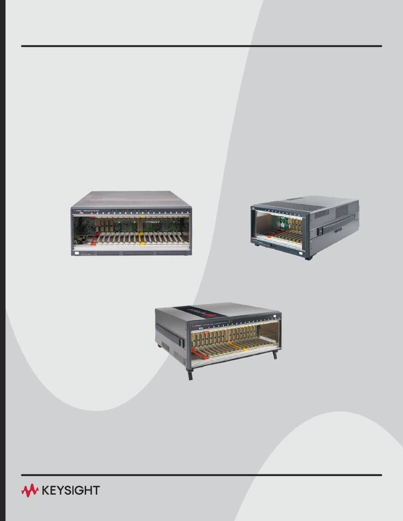
Keysight M9018A User manual

Keysight M9018A
PXIe Chassis
User Guide


Notices
© Keysight Technologies, Inc. 2014
No part of this manual may be repro-
duced in any form or by any means
(including electronic storage and retrieval
or translation into a foreign language)
without prior agreement and written con-
sent from Keysight Technologies, Inc. as
governed by United States and interna-
tional copyright laws.
Manual Part Number
M9018-90005
Edition
Seventh Edition, September 2014
Published in U.S.A.
900 S. Taft Avenue
Loveland, CO. 80537
Trademarks
LabVIEW®is a registered trademark of
National Instruments.
PXI®is a registered trademark of the PXI
Systems Alliance.
PICMG®, Compact PCI®, and
AdvancedTCA®are registered trade-
marks of the PCI Industrial Computer
Manufacturers Group.
PCI-SIG®, PCI Express®, and PCIe®are
registered trademarks of PCI-SIG.
Sales and Technical Support
To contact Keysight for sales and techni-
cal support, refer to the support links on
the following Keysight websites:
www.keysight.com/find/9018A (product-
specific information and support, soft-
ware and documentation updates)
www.keysight.com/find/assist (world-
wide contact information for repair and
service)
Information on preventing damage to
your Keysight equipment can be found at
www.keysight.com/find/tips.
Declaration of Conformity
Declarations of Conformity for this prod-
uct and for other Keysight products may
be downloaded from the Web. Go to
http://keysight.com/go/conformity and
click on “Declarations of Conformity.” You
can then search by product number to
find the latest Declaration of Conformity.
Technology Licenses
The hardware and/or software described
in this document are furnished under a
license and may be used or copied only in
accordance with the terms of such
license.
Warranty
THE MATERIAL CONTAINED IN THIS
DOCUMENT IS PROVIDED “AS IS,” AND
IS SUBJECT TO BEING CHANGED,
WITHOUT NOTICE, IN FUTURE EDI-
TIONS. FURTHER, TO THE MAXIMUM
EXTENT PERMITTED BY APPLICABLE
LAW, KEYSIGHT DISCLAIMS ALL WAR-
RANTIES, EITHER EXPRESS OR IMPLIED,
WITH REGARD TO THIS MANUAL AND
ANY INFORMATION CONTAINED
HEREIN, INCLUDING BUT NOT LIMITED
TO THE IMPLIED WARRANTIES OF MER-
CHANTABILITY AND FITNESS FOR A
PARTICULAR PURPOSE. KEYSIGHT
SHALL NOT BE LIABLE FOR ERRORS OR
FOR INCIDENTAL OR CONSEQUENTIAL
DAMAGES IN CONNECTION WITH THE
FURNISHING, USE, OR PERFORMANCE
OF THIS DOCUMENT OR OF ANY INFOR-
MATION CONTAINED HEREIN. SHOULD
KEYSIGHT AND THE USER HAVE A SEP-
ARATE WRITTEN AGREEMENT WITH
WARRANTY TERMS COVERING THE
MATERIAL IN THIS DOCUMENT THAT
CONFLICT WITH THESE TERMS, THE
WARRANTY TERMS IN THE SEPARATE
AGREEMENT SHALL CONTROL.
Keysight Technologies does not warrant
third-party system-level (combination of
chassis, controllers, modules, etc.) per-
formance, safety, or regulatory compli-
ance unless specifically stated.
DFARS/Restricted Rights
Notices
If software is for use in the performance
of a U.S. Government prime contract or
subcontract, Software is delivered and
licensed as “Commercial computer soft-
ware” as defined in DFAR 252.227-7014
(June 1995), or as a “commercial item” as
defined in FAR 2.101(a) or as “Restricted
computer software” as defined in FAR
52.227-19 (June 1987) or any equivalent
agency regulation or contract clause.
Use, duplication or disclosure of Software
is subject to Keysight Technologies’ stan-
dard commercial license terms, and non-
DOD Departments and Agencies of the
U.S. Government will receive no greater
than Restricted Rights as defined in FAR
52.227-19(c)(1-2) (June 1987). U.S. Gov-
ernment users will receive no greater
than Limited Rights as defined in FAR
52.227-14 (June 1987) or DFAR 252.227-
7015 (b)(2) (November 1995), as applica-
ble in any technical data.

Safety Information
The following general safety precau-
tions must be observed during all
phases of operation of this instrument.
Failure to comply with these precau-
tions or with specific warnings or oper-
ating instructions in the product
manuals violates safety standards of
design, manufacture, and intended use
of the instrument. Keysight Technolo-
gies assumes no liability for the cus-
tomer's failure to comply with these
requirements.
General
Do not use this product in any manner not
specified by the manufacturer. The protec-
tive features of this product must not be
impaired if it is used in a manner specified in
the operation instructions.
Before Applying Power
Verify that all safety precautions are taken.
Make all connections to the unit before
applying power. Note the external markings
described under “Safety Symbols”.
Ground the Instrument
Keysight chassis’ are provided with a
grounding-type power plug. The
instrument chassis and cover must be
connected to an electrical ground to
minimize shock hazard. The ground pin
must be firmly connected to an electri-
cal ground (safety ground) terminal at
the power outlet. Any interruption of
the protective (grounding) conductor
or disconnection of the protective
earth terminal will cause a potential
shock hazard that could result in per-
sonal injury.
Do Not Operate in an Explosive
Atmosphere
Do not operate the module/chassis in
the presence of flammable gases or
fumes.
Do Not Operate Near Flammable
Liquids
Do not operate the module/chassis in
the presence of flammable liquids or
near containers of such liquids.
Cleaning
Clean the outside of the Keysight mod-
ule/chassis with a soft, lint-free,
slightly dampened cloth. Do not use
detergent or chemical solvents.
Do Not Remove Instrument Cover
Only qualified, service-trained person-
nel who are aware of the hazards
involved should remove instrument
covers. Always disconnect the power
cable and any external circuits before
removing the instrument cover.
Keep away from live circuits
Operating personnel must not remove
equipment covers or shields. Proce-
dures involving the removal of covers
and shields are for use by service-
trained personnel only. Under certain
conditions, dangerous voltages may
exist even with the equipment
switched off. To avoid dangerous elec-
trical shock, DO NOT perform proce-
dures involving cover or shield removal
unless you are qualified to do so.
DO NOT operate damaged
equipment
Whenever it is possible that the safety
protection features built into this prod-
uct have been impaired, either through
physical damage, excessive moisture,
or any other reason, REMOVE POWER
and do not use the product until safe
operation can be verified by service-
trained personnel. If necessary, return
the product to an Keysight Technolo-
gies Sales and Service Office for ser-
vice and repair to ensure the safety
features are maintained.
DO NOT block the primary
disconnect
The primary disconnect device is the
appliance connector/power cord when
a chassis used by itself, but when
installed into a rack or system the dis-
connect may be impaired and must be
considered part of the installation.
Do Not Modify the Instrument
Do not install substitute parts or per-
form any unauthorized modification to
the product. Return the product to an
Keysight Sales and Service Office to
ensure that safety features are main-
tained.
In Case of Damage
Instruments that appear damaged or
defective should be made inoperative
and secured against unintended oper-
ation until they can be repaired by
qualified service personnel.
Do NOT block vents and fan exhaust:
To ensure adequate cooling and venti-
lation, leave a gap of at least 50mm
(2") around vent holes on both sides of
the chassis.
Do NOT operate with empty slots: To
ensure proper cooling and avoid dam-
aging equipment, fill each empty slot
with an AXIe filler panel module.
Do NOT stack free-standing chassis:
Stacked chassis should be rack-
mounted.
All modules are grounded through the
chassis: During installation, tighten
each module's retaining screws to
secure the module to the chassis and
to make the ground connection.
Operator is responsible to maintain
safe operating conditions. To ensure
safe operating conditions, modules
should not be operated beyond the full
temperature range specified in the
Environmental and physical specifica-
tion. Exceeding safe operating condi-
tions can result in shorter lifespan,
improper module performance and
user safety issues. When the modules
are in use and operation within the
specified full temperature range is not
maintained, module surface tempera-
tures may exceed safe handling condi-
tions which can cause discomfort or
burns if touched. In the event of a
module exceeding the full temperature
range, always allow the module to cool
before touching or removing modules
from the chassis.
iv

Safety Symbols
A CAUTION denotes a hazard. It
calls attention to an operating pro-
cedure or practice that, if not cor-
rectly performed or adhered to,
could result in damage to the
product or loss of important data.
Do not proceed beyond a CAUTION
notice until the indicated condi-
tions are fully understood and met.
A WARNING denotes a hazard. It
calls attention to an operating pro-
cedure or practice, that, if not cor-
rectly performed or adhered to,
could result in personal injury or
death. Do not proceed beyond a
WARNING notice until the indi-
cated conditions are fully under-
stood and met.
Products display the following sym-
bols:
The CSA mark is a registered trade-
mark of the Canadian Standards Asso-
ciation and indicates compliance to
the standards laid out by them. Refer
to the product Declaration of Confor-
mity for details.
Notice for European Community: This
product complies with the relevant
European legal Directives: EMC Direc-
tive (2004/108/EC) and Low Voltage
Directive (2006/95/EC).
The Regulatory Compliance Mark
(RCM) mark is a registered trademark.
This signifies compliance with the Aus-
tralia EMC Framework regulations
under the terms of the Radio Commu-
nication Act of 1992.
ICES/NMB-001 indicates that this ISM
device complies with the Canadian
ICES-001.
This symbol represents the time period
during which no hazardous or toxic
substance elements are expected to
leak or deteriorate during normal use.
Forty years is the expected useful life
of this product.
South Korean Class A EMC Declara-
tion. this equipment is Class A suitable
for professional use and is for use in
electromagnetic environments outside
of the home.
Waste Electrical and
Electronic
Equipment (WEEE)
Directive
2002/96/EC
This product complies with the WEEE
Directive (2002/96/EC) marking
requirement. The affixed product label
(see below) indicates that you must not
discard this electrical/electronic prod-
uct in domestic household waste.
Product Category: With reference to
the equipment types in the WEEE
directive Annex 1, this product is clas-
sified as a “Monitoring and Control
instrumentation” product.
Do not dispose in domestic household
waste.
To return unwanted products, contact
your local Keysight office, or see
www.keysight.com/environment/prod-
uct for more information.
Refer to manual for
additional safety
information.
Earth Ground.
Chassis Ground.
Alternating Current (AC).
Direct Current (DC).
Standby Power. Unit is not
completely disconnected
from AC mains when
power switch is in standby
position
Indicates that antistatic
precautions should be
taken.
Operate the PXIe chassis
in the horizontal
orientation. Do NOT
operate this chassis in the
vertical orientation.
v

vi

Keysight M9195A Digital Stimulus/Response Module User Guide vii
Contents
1 Introduction
About this Guide . . . . . . . . . . . . . . . . . . . . . . . . . . . . . . . . . . . . . . . . . . . . . . . . . 2
M9018A Block Diagram . . . . . . . . . . . . . . . . . . . . . . . . . . . . . . . . . . . . . . . . . . . . 4
Chassis maintenance and inspection . . . . . . . . . . . . . . . . . . . . . . . . . . . . . . . . 7
Module handling procedures. . . . . . . . . . . . . . . . . . . . . . . . . . . . . . . . . . . . . . . . 8
Installing modules in the chassis. . . . . . . . . . . . . . . . . . . . . . . . . . . . . . . . . . . . . 9
2 Power Supply Operation
Voltage rails . . . . . . . . . . . . . . . . . . . . . . . . . . . . . . . . . . . . . . . . . . . . . . . . . . . . 12
Power supply capacity . . . . . . . . . . . . . . . . . . . . . . . . . . . . . . . . . . . . . . . . . . . . 13
Over temperature protection . . . . . . . . . . . . . . . . . . . . . . . . . . . . . . . . . . . . . . . 14
Temperature derating of the primary power module . . . . . . . . . . . . . . . . . . . . 15
Power calculator spreadsheet . . . . . . . . . . . . . . . . . . . . . . . . . . . . . . . . . . . . . . 16
Overcurrent protection of the 5V and 12V rails maximum PPM . . . . . . . . . . . . 16
Short circuit protection of the 5V and 12V rails . . . . . . . . . . . . . . . . . . . . . . . . 16
Short circuit protection of the 3.3V rail . . . . . . . . . . . . . . . . . . . . . . . . . . . . . . . 17
Monitoring of the 3.3V rail by the chassis . . . . . . . . . . . . . . . . . . . . . . . . . . . . . 17
Internal fuses . . . . . . . . . . . . . . . . . . . . . . . . . . . . . . . . . . . . . . . . . . . . . . . . . . . 17
Measuring the four main voltage rails directly . . . . . . . . . . . . . . . . . . . . . . . . . 18
3 Chassis Cooling and Rack Mounting
Overview of chassis cooling. . . . . . . . . . . . . . . . . . . . . . . . . . . . . . . . . . . . . . . . 19
Rack mounting of the chassis . . . . . . . . . . . . . . . . . . . . . . . . . . . . . . . . . . . . . . 20
4 Chassis and Host Controller Power Up/Down Sequence
Power sequence requirements . . . . . . . . . . . . . . . . . . . . . . . . . . . . . . . . . . . . . 22
PC startup events for Keysight IO Libraries Suite . . . . . . . . . . . . . . . . . . . . . . . 23
PC startup events for Keysight IO Libraries Suite 16.0 . . . . . . . . . . . . . . . . 24

viii Keysight M9195A Digital Stimulus/Response Module User Guide
PC startup events for Keysight IO Libraries Suite 16.1 or later . . . . . . . . . . 26
Performing a system restart. . . . . . . . . . . . . . . . . . . . . . . . . . . . . . . . . . . . . . . . 27
Performing a chassis hard reset . . . . . . . . . . . . . . . . . . . . . . . . . . . . . . . . . . . . 28
5 Overview of Chassis Management Capabilities
Summary of chassis management capabilities. . . . . . . . . . . . . . . . . . . . . . . . . 30
Enabling use of the SFP to configure chassis parameters . . . . . . . . . . . . . . . . 30
The chassis alarm architecture . . . . . . . . . . . . . . . . . . . . . . . . . . . . . . . . . . . . . 31
6 Viewing the Chassis Revision and Updating Firmware
Viewing the chassis revision information using the SFP. . . . . . . . . . . . . . . . . . 33
Viewing the chassis revision information using the IVI drivers . . . . . . . . . . . . . 34
Chassis firmware revision checking and installation. . . . . . . . . . . . . . . . . . . . . 34
7 The Chassis Alarm Architecture
Relationship between Alarm Occurred and the front panel LEDs . . . . . . . . . . 37
Power-on default alarm thresholds . . . . . . . . . . . . . . . . . . . . . . . . . . . . . . . . . . 38
Events which re-establish the power-on default thresholds . . . . . . . . . . . . 39
The SFP alarm thresholds. . . . . . . . . . . . . . . . . . . . . . . . . . . . . . . . . . . . . . . 39
8 Monitoring Fan Speeds
9 Monitoring the Chassis Temperature
10 Setting the Fan Speed vs. Chassis Temperature Profile
11 Monitoring the Power Supply Rails
12 Monitoring the 10 MHz Reference Clock Source
Monitoring the 10 MHz clock source. . . . . . . . . . . . . . . . . . . . . . . . . . . . . . . . . 59
13 Configuring the PXI Trigger Bus
Configuring PXI trigger bus connections. . . . . . . . . . . . . . . . . . . . . . . . . . . . . . 65
Using the SFP to configure PXI trigger bus connections. . . . . . . . . . . . . . . 65
Using the IVI drivers to configure trigger bus connections . . . . . . . . . . . . . 66
14 Changing and Restoring the PCIe Link Configuration
Selecting a Link Configuration. . . . . . . . . . . . . . . . . . . . . . . . . . . . . . . . . . . . . . 72
Using the PCIe Switch Fabric Configurator program . . . . . . . . . . . . . . . . . . . . 75
Configuring the chassis to run at Gen 1 speeds . . . . . . . . . . . . . . . . . . . . . 83

Keysight M9195A Digital Stimulus/Response Module User Guide ix
Reconfiguration failure . . . . . . . . . . . . . . . . . . . . . . . . . . . . . . . . . . . . . . . . . 84
Restoring operation after an interruption of the configuration process . . . 85
Preemptively restoring the factory default 1x8 Base Configuration . . . . . . . . 87
15 Performing a Chassis Self Test
Performing self test using the IVI drivers . . . . . . . . . . . . . . . . . . . . . . . . . . . . . 93
Self test codes and messages. . . . . . . . . . . . . . . . . . . . . . . . . . . . . . . . . . . . . . 95
Low-numbered self test codes (service typically is required) . . . . . . . . . . . 95
High numbered self test codes (situation may be customer resolvable) . . 96
16 Troubleshooting the M9018A System
Overarching objective . . . . . . . . . . . . . . . . . . . . . . . . . . . . . . . . . . . . . . . . . . . 101
Quick troubleshooting tips . . . . . . . . . . . . . . . . . . . . . . . . . . . . . . . . . . . . . . . 101
Troubleshooting tools . . . . . . . . . . . . . . . . . . . . . . . . . . . . . . . . . . . . . . . . . . . 102
Spare parts . . . . . . . . . . . . . . . . . . . . . . . . . . . . . . . . . . . . . . . . . . . . . . . . . 102
Troubleshooting system exceptions . . . . . . . . . . . . . . . . . . . . . . . . . . . . . . . . 103
Exception #1: Chassis doesn’t power up . . . . . . . . . . . . . . . . . . . . . . . . . . 103
Exception #2: Abnormal fan behavior . . . . . . . . . . . . . . . . . . . . . . . . . . . . 103
Exception #3: Abnormal behavior of the front panel LEDs . . . . . . . . . . . . 104
Exception #4: Chassis alarm(s) are set . . . . . . . . . . . . . . . . . . . . . . . . . . . 105
Exception #5: Self test completes with messages. . . . . . . . . . . . . . . . . . . 106
Exception #6: Host controller PC can’t communicate to the chassis . . . . 106
17 Troubleshooting Failure of the Chassis to Power Up
Behavior of a powered up chassis. . . . . . . . . . . . . . . . . . . . . . . . . . . . . . . . . . 107
Power supply background information . . . . . . . . . . . . . . . . . . . . . . . . . . . . . . 108
Power supply and fan architecture. . . . . . . . . . . . . . . . . . . . . . . . . . . . . . . 108
Identifying the power supply version . . . . . . . . . . . . . . . . . . . . . . . . . . . . . 109
Troubleshooting failure of the chassis to power up . . . . . . . . . . . . . . . . . . . . 111
Verify AC power . . . . . . . . . . . . . . . . . . . . . . . . . . . . . . . . . . . . . . . . . . . . . 111
Troubleshoot the power up hardware . . . . . . . . . . . . . . . . . . . . . . . . . . . . 111
Remove and re-install modules . . . . . . . . . . . . . . . . . . . . . . . . . . . . . . . . . 113
Troubleshoot the power supply . . . . . . . . . . . . . . . . . . . . . . . . . . . . . . . . . 113
Power supply troubleshooting table . . . . . . . . . . . . . . . . . . . . . . . . . . . . . 114
18 Troubleshooting Fan Issues
Fan background information . . . . . . . . . . . . . . . . . . . . . . . . . . . . . . . . . . . . . . 115
Troubleshooting fan issues . . . . . . . . . . . . . . . . . . . . . . . . . . . . . . . . . . . . . . . 116
Fan troubleshooting table . . . . . . . . . . . . . . . . . . . . . . . . . . . . . . . . . . . . 117

x Keysight M9195A Digital Stimulus/Response Module User Guide
19 Troubleshooting Flashing of the Front Panel LEDs
Troubleshooting abnormal LED behaviors . . . . . . . . . . . . . . . . . . . . . . . . . . . 122
All three LEDs alternately blink for 1/3 Second then chassis shuts down 123
Troubleshooting out-of-limits power supplies . . . . . . . . . . . . . . . . . . . . . . . . 125
Troubleshooting chassis temperatures that are over the maximum temperature
threshold . . . . . . . . . . . . . . . . . . . . . . . . . . . . . . . . . . . . . . . . . . . . . . . . . . . . . 126
20 Troubleshooting the Chassis Alarms
Troubleshooting the chassis alarms . . . . . . . . . . . . . . . . . . . . . . . . . . . . . . . . 127
21 Troubleshooting Based on the Self Test Results
Low-numbered codes (service is typically required) . . . . . . . . . . . . . . . . . 130
High numbered self test codes (situation may be customer resolvable). . 132
22 Troubleshooting M9018A System Turn On Issues
M9018A system components and settings . . . . . . . . . . . . . . . . . . . . . . . . . . . 140
Host controller PC . . . . . . . . . . . . . . . . . . . . . . . . . . . . . . . . . . . . . . . . . . . . . . 144
Tested computer list . . . . . . . . . . . . . . . . . . . . . . . . . . . . . . . . . . . . . . . . . . 144
Keysight IO Libraries Suite and the chassis drivers . . . . . . . . . . . . . . . . . . 144
PCIe slots and speeds. . . . . . . . . . . . . . . . . . . . . . . . . . . . . . . . . . . . . . . . . 145
M9018A chassis . . . . . . . . . . . . . . . . . . . . . . . . . . . . . . . . . . . . . . . . . . . . . . . . 146
M9021A Cable Interface module . . . . . . . . . . . . . . . . . . . . . . . . . . . . . . . . 146
Windows Device Manager and Connection Expert views of the PCIe devices
149
23 Repairing the Chassis
Ordering the fan assembly and power supply. . . . . . . . . . . . . . . . . . . . . . . . . 158
Tools that you’ll need. . . . . . . . . . . . . . . . . . . . . . . . . . . . . . . . . . . . . . . . . . . . 158
Important aspects of the repair process . . . . . . . . . . . . . . . . . . . . . . . . . . . . . 159
Removing the rear panel . . . . . . . . . . . . . . . . . . . . . . . . . . . . . . . . . . . . . . . . . 159
Replacing the fan assembly. . . . . . . . . . . . . . . . . . . . . . . . . . . . . . . . . . . . . . . 164
Verifying the fan assembly . . . . . . . . . . . . . . . . . . . . . . . . . . . . . . . . . . . . . 165
Replacing the power supply . . . . . . . . . . . . . . . . . . . . . . . . . . . . . . . . . . . . . . 166
Installing the new power supply. . . . . . . . . . . . . . . . . . . . . . . . . . . . . . . . . 173
Verifying the power supply . . . . . . . . . . . . . . . . . . . . . . . . . . . . . . . . . . . . . 176

Keysight M9195A Digital Stimulus/Response Module User Guide xi
A How to Return the Chassis to Keysight
Failure information. . . . . . . . . . . . . . . . . . . . . . . . . . . . . . . . . . . . . . . . . . . . . . 178
B Chassis and Accessory Model Numbers
C Chassis Temperature Parameters
Index

xii Keysight M9195A Digital Stimulus/Response Module User Guide

M9018A PXIe 18-Slot Chassis
User Guide
1
1Introduction
The 18-slot Keysight M9018A PXIe Chassis has these key features:
-Contains an advanced PCIe switch fabric that operates at PCI Express
Generation 2 (“Gen 2”) speeds.
-Provides a mix of x4 and x8 links to the module slots. At Gen 2 speeds, the x8
links can deliver data to modules at 4 GB/s when connected to an x8-capable
computer. Module-to-module communications are also supported at 4 GB/s
for modules installed in x8 capable slots.
-Supports multiple chassis. There are several possible ways to configure
multiple M9018A PXIe and M9502A 2-Slot and M9505A 5-Slot AXIe chassis
together; all of them controlled by a single host controller. The host controller
can be either a PXIe Embedded Controller (such as the Keysight M9036A) or a
desktop or rack-mounted computer. For detailed multiple PXIe and AXIe
chassis arrangement information, refer to Keysight's Multiple PXIe and AXIe
Chassis Configuration tool. This tool is available on the M9018A Product
information CD as well as on line at:
www.keysight.com/find/pxie-multichassis.
-A system timing module can be installed in the chassis to provide advanced
trigger signals to all slots.

2 Keysight M9018A PXIe 18-Slot Chassis User Guide
Introduction About this Guide
About this Guide
This User Guide provides detailed information on using the M9018A chassis,
including the following:
-How to configure the M9018A chassis to meet your needs. Parameters such
as the following can be configured:
–The PCIe link configuration: 1x8, 2x8, or 4x4
–Voltage limits around the power supply rails at which an alarm will be
generated if a rail falls outside of its limit
–The temperature at which an alarm will be generated if the chassis
exceeds this temperature
–The fan speed at which an alarm will be generated if a fan speed falls
below this limit
-How to ensure that your modules don’t exceed the chassis power supply
capacity.
-Rack mounting of the chassis
-How to diagnose and troubleshoot issues with the chassis
-How to replace the power supply or the fan assembly
It is assumed that you have used the M9018A Startup Guide to turn on the
chassis system, including installing the Keysight IO Libraries Suite, the chassis
drivers, and the chassis soft front panel. If the chassis has not yet been turned
on, please use the Startup Guide to perform the initial chassis turn on prior to
configuring the chassis as described in this guide.
If you have been unable to turn on the chassis system using the M9018A
Startup Guide and need assistance, please see “Troubleshooting M9018A
System Turn On Issues” on page 139. This appendix provides step-by-step
guidance on turning on the chassis system.
If you are still unable to turn on the chassis system, see “Troubleshooting the
M9018A System” on page 99. Note that having ready access to certain spare
parts may accelerate the troubleshooting process. Chapter 16 includes a list of
spare parts that you may want to acquire to support any repairs that are ever
needed.

Keysight M9018A PXIe 18-Slot Chassis User Guide 3
About this Guide Introduction
Before continuing, some important terminology is presented. The computer that
controls the chassis is known as the host controller or system controller, and is
shown at the top of the hierarchy in Figure 2:
Figure 1 The host controller, remote controller, and embedded controller
hierarchy
The host controller can either be a remote controller or an embedded controller.
A remote controller is a Windows-based PC, and can be a desktop PC, a laptop
PC, or a rack mounted PC. The remote controller interfaces to the chassis
through a PCIe cable.
An embedded controller, such as the Keysight M9036A Embedded Controller, is
a small form factor, Windows-based PC that is designed for installation in the
system controller slot (slot 1) of the chassis. An embedded controller also
consumes two or three expansion slots to the left of slot 1.
The combination of the chassis, the host controller (and a PCIe cable if the host
controller is a remote controller), and the chassis I/O software running on the
host controller is referred to as a chassis system.
Host Controller
(System Controller)
Remote Controller Embedded Controller
(installs in slot 1
of chassis)
(connects to chassis
through a PCIe cable)
Laptop PC
Desktop PC
Rack-mounted PC
In order for a PC to serve as a remote controller, its BIOS must support
enumeration of the PCIe slots in the chassis; many computers are not capable
of enumerating a sufficient number of PCIe slots to ensure that slots in an
external chassis are enumerated.
Keysight provides the document “PCI and AXIe Modular Instrumentation Tested
Computer List Technical Note” which lists the embedded, desktop, laptop, and
rack-mounted PCs that have been verified to enumerate the PCIe slots in the
M9018A chassis. Please use this document, available under the Document
Library tab at www.keysight.com/find/M9018A, to guide your selection of
remote controller PCs.
For general PC requirements, such as operating system and RAM requirements,
please see the section “Software Requirements” in the M9018A Startup Guide.

4 Keysight M9018A PXIe 18-Slot Chassis User Guide
Introduction M9018A Block Diagram
M9018A Block Diagram
The M9018A block diagram (non-interactive) from the Startup Guide is
presented on the next page. Please see the Startup Guide for a description of the
key elements on the diagram and for information on how to use the interactive
features. View the complete interactive block diagram from the Windows Start
button:
Start > All Programs > Keysight > M9018 > M9018 Block Diagram
You can also view the block diagram on the Software and Product Information
CD or you can download the block diagram from
www.keysight.com/find/M9018A.

Keysight M9018A PXIe 18-Slot Chassis User Guide 5
M9018A Block Diagram Introduction

Keysight M9018A PXIe Chassis User Guide 6
Slot 2 Slot 3 Slot 4 Slot 5 Slot 6 Slot 13 Slot 14 Slot 15 Slot 16 Slot 17
Slot 7 Slot 8 Slot 9 Slot 11 Slot 12Slot 10
Slot 18
Slot 1
System
Controller
Slot
Hybrid Slots
PCIe Cable
Interface (x8)
PCIe
Desktop
Adapter (x8)
Clear
1x8
2x8
4x4
System
Timing Slot
XP4
XP3
XP2
XJ1
XP4
XP3
XP1
Show Triggers
XP3
TP2
TP1
x8
PCIe Switch Fabric
x4 x4 x4 x8 x4 x4x4
VCXO
Show Clocks
Clear
PXI_TRIG[0:7]
PXI_STAR[0:16]
PXIe_DSTAR A/B/C[0:16]
PXI_CLK10
Clock
Generator
Sync
Generator
PXI_CLK10_IN
Show
SMBus
PLL
FEEDBACK
10 MHZ REF IN
x1 x4 x8 x4 x4 x4 x8 x4 x4 x4
x1 x1
Show PCIe Link Configurations
10 MHZ
REF OUT
PLL
PXI_CLK10_IN
Front panel
ON/Standby
pushbutton
DB-9 Connector
Pin Signal
1 Logic ground
2+5VDC
3 Reserved
4+3.3VDC
5Inhibit (active low)
6+12VDC
7 Reserved
8 -12 VDC
9 Logic ground
Power
Supply
PXIe_CLK100
Eight backplane
temperature sensors
Remote Controllers
Hybrid Slots
In
Y1200B
PCIe cable: x1 to x8
connectors, 2.0m
Y1202A
PCIe cable: x8,
2.0m
Show Boards Supported
by the Hybrid Slots
XP4
10
Clear
PXI_CLK10
PXIe_CLK100
PXIe_SYNC100
Chassis
EPROM
INHIBIT
(rear panel)
ON
Primary
Power Module
(PPM)
3.3V
5V
12V
-12V
DEF
(default)
MAN
(manual)
5Vaux
5Vaux
PXIe_SYNC100
10 MHZ
INPUT
10 MHZ
OUTPUT
Chassis Manager
Chassis firmware
(customer upgradeable)
x1 10 MHz
Input
Select
Chassis
10 MHz
Correction
Signal
VCXO
Input
Select
(rear panel
BNC)
(rear panel BNC)
ON/Standby pushbutton power activation signal
Show Hybrid Slot Pin Outs
PCIe Switch Fabric Configurator
This program can be used to set the
User Configuration to 2x8 or 4x4
(and point the virtual switch to the
User Configuration), or point the
switch to the Base Configuration.
Load Base
Configuration
Pushbutton
Please place your mouse
over this rounded rectangle
to view information
about this diagram.
START HERE
Embedded
Controller
Keysight M9018A PXIe Chassis
User Configuration Base Configuration: 1x8
User Base
Show Chassis Views
Clear
Front View
Rear View
C20 power connector
(rear panel)
Show Host Controller Software
Clear
Keysight Connection Expert
Soft Front Panel
Development environments
Link 1 Link 2 Link 3 Link 4
1x4
2x4
3x4
4x4
Possible
PCIe 4-Link
Configurations
Link 1 Link 2
1x8
2x8
Lanes per link
Possible
PCIe 2-Link
Configurations
Total number of
x4 links used
Links used of the four x4 links available
Lanes per link
Total number of
x8 links used
Links used of the two x8 links available
PCIe 2-Link and 4-Link Configurations
Factory
default
When the host controller PC boots, it asserts its PCIe
Reset signal which causes the User or Base Configuration
to be loaded into the PCIe Switch Fabric, depending on the
virtual switch position.
virtual switch
INHIBIT/VOLTAGE MON
(rear panel)
Monitor
Processor
Factory
default,
read-only
© Keysight Technologies, Inc. 2012, 2013, 2014
September 2014M9018-90006
AUTO
HIGH
FAN
(rear panel)
Fan Monitor
and Control
Fan 12V
To module
slots and
chassis
electronics
5Vstandby
Fan assembly
ON/Standby
pushbutton
power activation
signal
Inhibit
(low = off)
PCIe
ExpressCard
Adapter (x1)
si
gh
t
T
ec
hn
ol
og
ie
s
I
nc
20
12
20

Keysight M9018A PXIe 18-Slot Chassis User Guide 7
Chassis maintenance and inspection
No periodic maintenance of the chassis is required. However, Keysight
recommends monitoring the following chassis parameters on an ongoing basis:
-Power supply voltages—The four main power supply rails (3.3V, 5V, 12V, and
–12V) should all be within ±5% of their nominal values. Keysight recommends
checking the power rails at least yearly using the chassis soft front panel
(SFP) or programmatically. In addition, the power rails are accessible on the
rear panel DB-9 connector, and can be checked with a DMM as described in
“Measuring the four main voltage rails directly” on page 18.
-Fan speeds—The chassis has three fans located at the rear of the chassis. A
low fan speed possibly indicates that a fan is wearing out or a fan blade is
partially obstructed. Keysight recommends using the chassis SFP to check
the fan speeds yearly as well.
-Chassis firmware—Keysight recommends that you periodically check to see if
there is a chassis firmware revision available that is later than your chassis
firmware revision. If so, it is suggested that you download and install the latest
firmware revision available as described in “Chassis firmware revision
checking and installation” on page 34.
If a power supply voltage is out of tolerance or a fan speed is low, please see
“Troubleshooting the M9018A System” on page 99 for diagnostic information
and troubleshooting tips.
- This is a Safety Class 1 Product (provided with a protective earthing ground
incorporated in the power cord). The mains plug shall only be inserted in a
socket outlet provided with a protective earth contact. Any interruption of
the protective conductor inside or outside of the product is likely to make
the product dangerous. Intentional interruption is prohibited. Inspect the
protective conductor periodically to ensure that it is uninterrupted.
- No operator serviceable parts inside. Refer servicing to qualified personnel.
To prevent electrical shock, do not remove covers.
- To prevent electrical shock, disconnect the chassis power cord before
cleaning. Use a dry cloth or one slightly dampened with water to clean the
external case parts. Do not attempt to clean internally.
- Cleaning connectors with alcohol shall only be done with the chassis power
cord removed and in a well-ventilated area. Allow all residual alcohol
moisture to evaporate, and the fumes to dissipate prior to energizing the
chassis.

8 Keysight M9018A PXIe 18-Slot Chassis User Guide
Module handling procedures
To avoid electrostatic discharge damage when handling modules, please read
and follow the guidelines provided below.
Electrostatic discharge (ESD) can damage or destroy electronic components.
Keysight modules and interface cards are shipped in materials which prevent
static electricity damage. These items should only be unpacked and inspected
at a static-safe work station. The following figure shows an example of a
static-safe work station which uses the following two ESD protection methods:
-Conductive table-mat and
wrist-strap combination.
-Conductive floor-mat and heel-strap
combination.
ESD protection accessories can be
purchased from numerous electronics
suppliers.
Both ESD protection methods listed above, when used together, provide a
significant level of protection. Of the two methods, only the table-mat and
wrist-strap combination (method 1) provides adequate ESD protection when
used alone. To ensure user safety, the static-safe accessories must provide at
least 1 Mof isolation from ground.
To avoid damaging components when unpacking or handling a module, do not
touch the module connector pins or the components on the printed circuit
board. Store all modules and interface cards in anti-static envelopes when not
in use.
Additional information on preventing damage to your Keysight equipment can
be found at www.keysight.com/find/tips.
Other manuals for M9018A
1
Table of contents
Other Keysight Chassis manuals

Keysight
Keysight Ixia XGS2 User manual

Keysight
Keysight PXIe M9018B User guide

Keysight
Keysight ixia XGS12 User manual

Keysight
Keysight E8401A Troubleshooting guide

Keysight
Keysight PXIe M9010A User guide

Keysight
Keysight PXIe Series Use and care manual

Keysight
Keysight M9514A User guide

Keysight
Keysight M9018A User guide

Keysight
Keysight Ixia IxOS XGS2 Series User manual

Keysight
Keysight M9514A Operating instructions