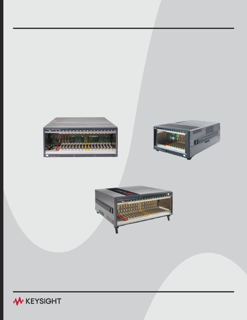
Keysight PXIe M9018B User guide


Notices
© Keysight Technologies, Inc. 2018
No part of this manual may be repro-
duced in any form or by any means
(including electronic storage and retrieval
or translation into a foreign language)
without prior agreement and written con-
sent from Keysight Technologies, Inc. as
governed by United States and interna-
tional copyright laws.
Manual Part Number
M9019-90001
Edition
Third Edition, May 2018
Printed in
Malaysia
Published by
Keysight Technologies, Inc.
900 S. Taft Ave.
Loveland, CO 80537 USA
Trademarks
PICMG®, Compact PCI® are registered
trademarks of the PCI Industrial Com-
puter Manufacturers Group.
PCI-SIG®, PCI Express®, and PCIe®are
registered trademarks of PCI-SIG.
LabVIEW is a registered trademark of
National Instruments
Sales and Technical Support
To contact Keysight for sales and techni-
cal support, refer to the support links on
the following Keysight websites:
www.keysight.com/find/M9010A
www.keysight.com/find/M9018B
www.keysight.com/find/M9019A
(product-specific information and sup-
port, software and documentation
updates)
www.keysight.com/find/assist (world-
wide contact information for repair and
service)
Declaration of Conformity
Declarations of Conformity for this prod-
uct and for other Keysight products may
be downloaded from the Web. Go to
http://keysight.com/go/conformity and
click on “Declarations of Conformity.” You
can then search by product number to
find the latest Declaration of Conformity.
Technology Licenses
The hardware and/or software described
in this document are furnished under a
license and may be used or copied only in
accordance with the terms of such
license.
Warranty
THE MATERIAL CONTAINED IN THIS
DOCUMENT IS PROVIDED “AS IS,” AND
IS SUBJECT TO BEING CHANGED,
WITHOUT NOTICE, IN FUTURE EDI-
TIONS. FURTHER, TO THE MAXIMUM
EXTENT PERMITTED BY APPLICABLE
LAW, KEYSIGHT DISCLAIMS ALL WAR-
RANTIES, EITHER EXPRESS OR IMPLIED,
WITH REGARD TO THIS MANUAL AND
ANY INFORMATION CONTAINED
HEREIN, INCLUDING BUT NOT LIMITED
TO THE IMPLIED WARRANTIES OF MER-
CHANTABILITY AND FITNESS FOR A
PARTICULAR PURPOSE. KEYSIGHT
SHALL NOT BE LIABLE FOR ERRORS OR
FOR INCIDENTAL OR CONSEQUENTIAL
DAMAGES IN CONNECTION WITH THE
FURNISHING, USE, OR PERFORMANCE
OF THIS DOCUMENT OR OF ANY INFOR-
MATION CONTAINED HEREIN. SHOULD
KEYSIGHT AND THE USER HAVE A SEP-
ARATE WRITTEN AGREEMENT WITH
WARRANTY TERMS COVERING THE
MATERIAL IN THIS DOCUMENT THAT
CONFLICT WITH THESE TERMS, THE
WARRANTY TERMS IN THE SEPARATE
AGREEMENT SHALL CONTROL.
Keysight Technologies does not warrant
third-party system-level (combination of
chassis, controllers, modules, etc.) per-
formance, safety, or regulatory compli-
ance unless specifically stated.
DFARS/Restricted Rights
Notices
If software is for use in the performance
of a U.S. Government prime contract or
subcontract, Software is delivered and
licensed as “Commercial computer soft-
ware” as defined in DFAR 252.227-7014
(June 1995), or as a “commercial item” as
defined in FAR 2.101(a) or as “Restricted
computer software” as defined in FAR
52.227-19 (June 1987) or any equivalent
agency regulation or contract clause.
Use, duplication or disclosure of Software
is subject to Keysight Technologies’ stan-
dard commercial license terms, and non-
DOD Departments and Agencies of the
U.S. Government will receive no greater
than Restricted Rights as defined in FAR
52.227-19(c)(1-2) (June 1987). U.S. Gov-
ernment users will receive no greater
than Limited Rights as defined in FAR
52.227-14 (June 1987) or DFAR 252.227-
7015 (b)(2) (November 1995), as applica-
ble in any technical data.

Safety Information
The following general safety precau-
tions must be observed during all
phases of operation of this instrument.
Failure to comply with these precau-
tions or with specific warnings or oper-
ating instructions in the product
manuals violates safety standards of
design, manufacture, and intended use
of the instrument. Keysight Technolo-
gies assumes no liability for the cus-
tomer's failure to comply with these
requirements.
General
Do not use this product in any manner not
specified by the manufacturer. The protec-
tive features of this product must not be
impaired if it is used in a manner specified in
the operation instructions.
Before Applying Power
Verify that all safety precautions are taken.
Make all connections to the unit before
applying power. Note the external markings
described under “Safety Symbols”.
Ground the Instrument
Keysight chassis’ are provided with a
grounding-type power plug. The
instrument chassis and cover must be
connected to an electrical ground to
minimize shock hazard. The ground pin
must be firmly connected to an electri-
cal ground (safety ground) terminal at
the power outlet. Any interruption of
the protective (grounding) conductor
or disconnection of the protective
earth terminal will cause a potential
shock hazard that could result in per-
sonal injury.
PXIe Chassis are for indoor use only.
Mains supply voltage fluctuations must
not exceed ±10% of the nominal sup-
ply voltage.
Transient overvoltages typically pres-
ent on the Mains supply (installation
CAT II)
Do Not Operate in an Explosive
Atmosphere
Do not operate in the presence of
flammable gases or fumes.
Do Not Operate Near Flammable
Liquids
Do not operate the module/chassis in
the presence of flammable liquids or
near containers of such liquids.
Cleaning
Clean the outside of the Keysight mod-
ule/chassis with a soft, lint-free,
slightly dampened cloth. Do not use
detergent or chemical solvents.
Do Not Remove Instrument Cover
Only qualified, service-trained person-
nel who are aware of the hazards
involved should remove instrument
covers. Always disconnect the power
cable and any external circuits before
removing the instrument cover.
Keep away from live circuits
Operating personnel must not remove
equipment covers or shields. Proce-
dures involving the removal of covers
and shields are for use by service-
trained personnel only. Under certain
conditions, dangerous voltages may
exist even with the equipment
switched off. To avoid dangerous elec-
trical shock, DO NOT perform proce-
dures involving cover or shield removal
unless you are qualified to do so.
DO NOT operate damaged
equipment
Whenever it is possible that the safety
protection features built into this prod-
uct have been impaired, either through
physical damage, excessive moisture,
or any other reason, REMOVE POWER
and do not use the product until safe
operation can be verified by service-
trained personnel. If necessary, return
the product to a Keysight Technologies
Sales and Service Office for service and
repair to ensure the safety features are
maintained.
DO NOT block the primary
disconnect
The primary disconnect device is the
appliance connector/power cord when
a chassis used by itself, but when
installed into a rack or system the dis-
connect may be impaired and must be
considered part of the installation.
Do Not Modify the Instrument
Do not install substitute parts or per-
form any unauthorized modification to
the product. Return the product to a
Keysight Sales and Service Office to
ensure that safety features are main-
tained.
In Case of Damage
Instruments that appear damaged or
defective should be made inoperative
and secured against unintended oper-
ation until they can be repaired by
qualified service personnel.
Do NOT block vents and fan exhaust:
To ensure adequate cooling and venti-
lation, leave a gap of at least 50mm
(2") around vent holes on both sides of
the chassis.
Do NOT operate with empty slots: To
ensure proper cooling and avoid dam-
aging equipment, fill each empty slot
with an AXIe filler panel module.
Do NOT stack free-standing chassis:
Stacked chassis should be rack-
mounted.
All modules are grounded through the
chassis: During installation, tighten
each module's retaining screws to
secure the module to the chassis and
to make the ground connection.
Operator is responsible to maintain
safe operating conditions. To ensure
safe operating conditions, modules
should not be operated beyond the full
temperature range specified in the
Environmental and physical specifica-
tion. Exceeding safe operating condi-
tions can result in shorter lifespan,
improper module performance and
user safety issues. When the modules
are in use and operation within the
specified full temperature range is not
maintained, module surface tempera-
tures may exceed safe handling condi-
tions which can cause discomfort or
burns if touched. In the event of a
module exceeding the full temperature
range, always allow the module to cool
before touching or removing modules
from the chassis.
iv

vi

Keysight PXIe Chassis Family Startup Guide vii
Contents
Introduction
About this guide. . . . . . . . . . . . . . . . . . . . . . . . . . . . . . . . . . . . . . . . . . . . . . . . . 10
About the Chassis . . . . . . . . . . . . . . . . . . . . . . . . . . . . . . . . . . . . . . . . . . . . . . . 11
Front Panel Trigger . . . . . . . . . . . . . . . . . . . . . . . . . . . . . . . . . . . . . . . . . . . . 12
Interactive Block Diagram . . . . . . . . . . . . . . . . . . . . . . . . . . . . . . . . . . . . . . . . . 13
Terminology . . . . . . . . . . . . . . . . . . . . . . . . . . . . . . . . . . . . . . . . . . . . . . . . . . . . 17
Static-safe Handling Procedures. . . . . . . . . . . . . . . . . . . . . . . . . . . . . . . . . . . . 18
Step1: Verify Shipment Contents
Chassis Shipment Verification . . . . . . . . . . . . . . . . . . . . . . . . . . . . . . . . . . . . . . 19
Step 2: Prepare the Hardware
Host Controller Hardware and Software Requirements . . . . . . . . . . . . . . . . . . 21
Setting up the Chassis on a Bench . . . . . . . . . . . . . . . . . . . . . . . . . . . . . . . . . . 22
Removing and Installing Filler Panels . . . . . . . . . . . . . . . . . . . . . . . . . . . . . . . . 22
Connecting a Remote Host PC to the Chassis . . . . . . . . . . . . . . . . . . . . . . . . . 23
Installing an Embedded Controller in the Chassis . . . . . . . . . . . . . . . . . . . . . . 25
Install Keysight IO Libraries Suite (Remote Host PC) . . . . . . . . . . . . . . . . . . . . 26
Install the PXIe Chassis Family Driver . . . . . . . . . . . . . . . . . . . . . . . . . . . . . . . . 26
Step 3: Turn On Chassis and Verify Operation
Chassis Power Sequencing . . . . . . . . . . . . . . . . . . . . . . . . . . . . . . . . . . . . . . . . 29
Methods of powering up the chassis . . . . . . . . . . . . . . . . . . . . . . . . . . . . . . 29
Chassis Front Panel LEDs . . . . . . . . . . . . . . . . . . . . . . . . . . . . . . . . . . . . . . . . . 30
Using Keysight Connection Expert . . . . . . . . . . . . . . . . . . . . . . . . . . . . . . . . . . 32
PC Startup Requirements for Keysight IO Libraries Suite . . . . . . . . . . . . . . 33
Using the Soft Front Panel (SFP) to Monitor the Chassis . . . . . . . . . . . . . . . . . 34
Starting the SFP and Selecting Hardware Mode or Simulation Mode . . . . 34
Using the SFP to Monitor the Chassis . . . . . . . . . . . . . . . . . . . . . . . . . . . . . 35

viii Keysight PXIe Chassis Family Startup Guide
Step 4: Overview of Installing and Verifying PXI/PXIe Modules
Installing Modules . . . . . . . . . . . . . . . . . . . . . . . . . . . . . . . . . . . . . . . . . . . . . . . 39
Installing the Module Software . . . . . . . . . . . . . . . . . . . . . . . . . . . . . . . . . . . . . 40
Verifying your Module . . . . . . . . . . . . . . . . . . . . . . . . . . . . . . . . . . . . . . . . . . . . 41
Related Documentation
Chassis Related Products and Accessories

PXIe Chassis Family
Startup Guide
9
1Introduction
A PXIe chassis is the backbone of a PXIe system. It contains a high performance
backplane giving the cards in the system the ability to communicate rapidly with
the host PC. It also provides power and cooling.
Keysight provides three PXIe chassis in the PXIe Chassis Family:
-M9010A – a 10-Slot PXI 24 GB/s, Gen 3 chassis
-M9018B – a 18-Slot PXI 8 GB/s, Gen 2 chassis
-M9019A – a 18-Slot PXI 24 GB/s, Gen 3 chassis
Unless specified, everything in this PXIe Chassis Family Startup
Guide pertains to all three PXI chassis. If there is anything that
uniquely pertains to one of the three chassis, it is noted.
This Startup Guide does not include information for the Keysight
M9018A 18-slot PXIe chassis. For more information on M9018A,
refer to the user documentation available at
www.keysight.com/find/M9018A.

10 Keysight PXIe Chassis Family Startup Guide
Introduction About this guide
About this guide
This Keysight PXIe Chassis Family Startup Guide describes how to connect the
chassis to a host PC, power-up the chassis and verify basic operation, including:
–The features and capabilities of the PXIe chassis.
–How the chassis is shipped and what is included with the chassis.
–Computer hardware and software requirements, installation of an
embedded controller, connection of a remote controller, and software
installation on the controller.
–How to use Keysight Connection Expert and the chassis Soft Front Panel
(SFP) to verify operation of the chassis.
–Overview of installing and verifying Keysight modules in the chassis.
The new PXIe Chassis Family driver is backward compatible with
the M9018A chassis. The M9018B is a drop-in replacement for the
M9018A. Both the M9018A and the M9018B work with driver
versions 1.5.80.1 and 1.6.242.1. Refer to the PXIe Chassis Family
User Guide for details information.

Keysight PXIe Chassis Family Startup Guide 11
About the Chassis Introduction
About the Chassis
The Keysight Chassis Family is designed for easy integration into large systems
containing multiple PXIe chassis and other, non-PXI instrumentation. The
Keysight PXIe chassis have these key features:
–Up to 16 PXIe hybrid slots (the M9010A has 8 hybrid slots), 1 PXIe timing
slot, and 1 PXIe system slot.
–4U chassis with innovative cooling design.
–Ultra high performance PCIe interface
-- The M9010A has Gen 3 fixed fabric, with a two-link (x8, x16) system slot
and x8 links to the hybrid/timing slots.
-- The M918B provides configurable 2-Link (2x8) and 4-Link (4x4) plus
M9021A configuration (1x8).
-- The M9019A provides Gen 3 fixed fabric, with a two-link (x8, x16)
system slot and x8 links to the hybrid/timing slots.
–High data bandwidth (maximum 24 GB/s system and 8 GB/s slot-to-slot).
–Multi-chassis power-sequencing using rear panel RJ-45 connectors.
–Front panel external trigger input/output ports.
–One common driver supports IVI-C and IVI.NET for all three chassis (and
the M9018A PXIe chassis).
Figure 1 shows a front view of the M9019A chassis. The M9018B chassis is
similar; the M9010A chassis is similar but has ten slots.
Figure 1 Keysight M9019A PXI Chassis (the other chassis are similar)

12 Keysight PXIe Chassis Family Startup Guide
Introduction About the Chassis
The following figure shows the M9019A chassis rear panel.The M9018B chassis
rear panel is similar; the M9010A chassis has two fans.
Front Panel Trigger
Two front panel SMB trigger connectors connect to the PXI [0:7] backplane
trigger bus in Trigger Bus Segment 1 in the M9010A chassis and Trigger Bus
Segment 2 in the M9018B and M9019A chassis. See the Chassis Family User
Guide for detailed information.
Figure 2 Keysight M9019A PXIe Chassis Rear and Side View
Figure 3 Chassis Front Panel Trigger Connectors (M9019A chassis shown)
Make certain that your test system application is not running when
you reconfigure these two trigger ports. Reconfiguring the ports
may cause an unexpected pulse on the trigger port lines.

Keysight PXIe Chassis Family Startup Guide 13
Interactive Block Diagram Introduction
Interactive Block Diagram
An interactive Block Diagram exists for all three chassis. This Block Diagram is
usable for training and understanding how the chassis works. You can download
the block diagram from:
www.keysight.com/find/pxi-blockdiagram
The Block Diagram and other information is available on the individual the web
pages of the three PXIe chassis:
www.keysight.com/find/M9010A
www.keysight.com/find/M9018B
www.keysight.com/find/M9019A

14 Keysight PXIe Chassis Family Startup Guide
Introduction Interactive Block Diagram

Keysight PXIe Chassis Family Startup Guide 15
Figure 1 Chassis Block Diagram

16 Keysight PXIe Chassis Family Startup Guide

Keysight PXIe Chassis Family Startup Guide 17
Terminology
Terminology
The combination of the chassis, the host controller (and a PCIe cable if the host
controller is a remote controller), and the chassis I/O software running on the
host controller is referred to as a chassis system. The computer that controls the
chassis is known as the host controller or system controller, and is shown at the
top of the hierarchy in the following figure:
The host controller can either be a remote controller or an embedded controller.
A remote controller can be a desktop or a rack mounted PC. The controller
interfaces to the chassis with an M9048B or M9049A Host Adapter PCIe
Interface modules (desktop adapter) installed in the PC, through a PCIe cable to
an M9022A, M9023A, or M9024A PXIe System Interface Module installed in slot
1 of the chassis. The M9048A and M9021A can be used with the M9018A and
M9018B chassis in Gen 2 mode.
An embedded controller, such as the Keysight M9037A Embedded Controller, is a
small form-factor, Windows-based PC that is designed for installation in the
system controller slot of the chassis (slot 1). An embedded controller consumes
two or three expansion slots to the left of slot 1. .
Figure 2 System Controller Types
For a PC to serve as a remote controller, its BIOS must enumerate
all the PCIe slots in the chassis. Many computers cannot
enumerate a sufficient number of PCIe slots and may not work for
your configuration.
Keysight provides the document Tested PC and PXI/AXIe Chassis
Configurations, which lists the embedded, desktop and
rack-mounted PCs that have been verified to enumerate the PCIe
slots in the PXIe chassis. Use this document, available under the
Document Library tab at www.keysight.com/find/pxi-chassis, to
guide your selection of remote controller PCs..

18 Keysight PXIe Chassis Family Startup Guide
Static-safe Handling Procedures
Electrostatic discharge (ESD) can
damage or destroy electronic
components. Use a static-safe work
station to perform at work on electronic
assemblies. The figure shows a
static-safe work station using two types
of ESD protection:
-Conductive table-mat and wrist-strap
combination
-Conductive floor-mat and heel-strap
combination
Both types, when used together, provide a significant level of ESD protection. Of
the two, only the table-mat and wrist-strap combination provides adequate ESD
protection when used alone. To ensure user safety, the static-safe accessories
must provide at least 1 MΩof isolation from ground.
DO NOT use these techniques for a static-safe work station when
working on circuitry with a voltage potential greater than 500
volts.

Keysight PXIe Chassis Family Startup Guide 19
Chassis Shipment Verification Step1: Verify Shipment Contents
Step1: Verify Shipment Contents
Depending on your order, your shipment may arrive in separate boxes. For
example, if you order the M9019A chassis, the M9022A PXIe System Interface
Module, and a Y1202A cable, your order may arrive in three separate boxes.
Carefully inspect your shipment for any shipping damage. Report any damage to
the shipping agent immediately, as such damage is not covered by warranty.
Chassis Shipment Verification
Verify that your chassis shipment contains the following items:
–Keysight PXIe Chassis (M9010A, M9018B, or M9019A).
–Appropriate power cord for your location.
–Printed Keysight PXIe Chassis Family Startup Guide (this document).
Keysight suggests that you save the chassis shipping container in
case it ever becomes necessary to return the chassis to Keysight
for service. Return the Chassis to Keysight for service.
The weight of an empty M9018B or M9019A PXIe chassis (no
modules installed in the chassis) is approximately 29.8 lbs (13.5
kg). Lift the chassis using a single side handle only when the
total chassis weight (chassis plus installed modules) does not
exceed 75 lbs (34.0 kg). Otherwise use both side handles to lift
the chassis.
The M9010A chassis weighs 30.91 lbs (14.02 kg).
Installing modules in any chassis may increase its weight to a
point where two people are required to lift the chassis. If two
people are not available, use a mechanical lift to lift the chassis.
The chassis should be transported using a rolling cart.

20 Keysight PXIe Chassis Family Startup Guide
Step 2: Prepare the Hardware Chassis Shipment Verification
Step 2: Prepare the Hardware
The following procedures should be followed to ensure safety and to
minimize the possibility of damaging electrical components:
-This product is designed for use in Installation Category II and
Pollution Degree 2, per IEC 61010 Second Edition and 664
respectively.
-These chassis are designed for indoor use only.
-Mains wiring and connectors shall be compatible with the connector
used in the premise electrical system. Failure to ensure adequate
earth grounding by not using correct components may cause product
damage and serious injury.
-Use only the power cord supplied with the chassis. Keysight power
cords ensure continuity between the chassis grounding-type power
plug and the safety ground terminal at the power outlet.
-Install the chassis so that the detachable power cord is readily
identifiable and is easily reached by the operator. The detachable
power cord is the chassis disconnecting device. It disconnects the
mains circuits from the mains supply to the chassis before other parts
of the chassis. The front panel switch is only a standby switch and is
not a LINE switch. Alternatively, an externally installed switch or
circuit breaker (which is readily identifiable and is easily reached by
the operator) may be used as a disconnecting device.
- The chassis does not support hot-swapping of modules; i.e., inserting
and removing modules with the chassis powered up. Before installing
modules in the chassis, power down the chassis but leave the power
cord connected to the AC mains because it serves as a ground and
helps protect the chassis and modules from electrostatic damage.
-To minimize the possibility of electrostatic discharge (ESD) damage
to a module while installing it, follow the handling procedures
described in Static-safe handling procedures.
Do not install modules in the peripheral slots yet. In this step, only slot 1,
the system controller slot, may have a module installed. Deferring the
installation of other modules until later will allow the chassis to be
turned on and verified in its simplest configuration.
This manual suits for next models
2
Table of contents
Other Keysight Chassis manuals

Keysight
Keysight Ixia XG12 User manual

Keysight
Keysight PXIe M9010A User guide

Keysight
Keysight ixia XGS12 User manual

Keysight
Keysight M9018A User manual

Keysight
Keysight PXIe Series Use and care manual

Keysight
Keysight M9502A User manual

Keysight
Keysight M9506A User manual

Keysight
Keysight M9018A User guide

Keysight
Keysight M9514A Operating instructions

Keysight
Keysight M9514A User guide