Keystone Krown Manual

Krown
Fan Filter Units
v001 – Issue Date: 02/23/22
© 2022 Keystone Clean Air Solutions. All rights reserved.
INSTALLATION + SERVICE MANUAL

For more information visit KeystoneCleanAir.com v001
Product Overview
Read and Save These Instructions..................................3
Before You Start...................................................................3
Introduction ..........................................................................4
Installation Instructions
Module Installation..............................................................5
Speed Controller Installation & Operation ......................6
Filter Installation ...............................................................14
Accessories ........................................................................15
Balancing
Balancing ............................................................................21
Balancing Un-Ducted Supply Units ...............................22
Balancing Ducted Supply – Pressure Independent and
Dependent Airflow Control ..............................................23
Balancing Ducted Supply – Pressure Independent and
Dependent Airflow Control ..............................................25
Service Instructions
Pre-Filter Cleaning.............................................................26
Motor Change ....................................................................27
Room Side Accessible Controls .....................................32
Troubleshooting – Changing Motor Programs...........35
Troubleshooting
Troubleshooting Tips........................................................36
Replacement Parts
Filters ...................................................................................37
Motor/Blower .....................................................................37
Control Box Components.................................................38
For more information visit KeystoneCleanAir.com v001
2
Krown Fan Filter Units | Table of Contents

Read and Save These Instructions
Warning! To reduce the risk of re, electrical shock, or injury to persons, observe the following:
A. Installation work and electrical wiring must be done by qualied person(s) in accordance with all applicable codes and
standards, including re-rated construction.
B. When cutting or drilling into wall or ceiling, do not damage electrical wiring and other hidden utilities.
C. Use this unit only in the manner intended by the manufacturer. If you have any questions, contact the manufacturer:
In the United States
2975 20 Crestridge Drive, Suwanee, GA, 30024
Ph: 470.702.9560
D. Disconnect the unit from the electrical power source before attempting any service. Electrical service should be
performed by a licensed electrician or authorized service technician.
E. When performing any type of maintenance on the Krown Fan Filter Units, be careful to reduce as much as possible
the potential for introducing the internals of the unit to dirt, dust, and debris that may be present in the unit's external
environment.
F. To reduce the risk of injury to persons, install the unit at least 7ft above grade or in ceiling.
Before You Start
Shipping Information
Inspect all cartons and boxes for flaws and shipping damages. If anything is discovered to be damaged, contact the shipping
company and le a freight claim.
Filter Information
Ensure that all HEPA/ULPA lters are stored in a clean, dry location in a vertical position, as labeled on the carton. Do not
open the HEPA/ULPA lters until they are ready to be installed in the Krown Fan Filter Units. All construction in the space
should be complete, the site and upstream air should be clean so as not to unnecessarily load the lter.
Ensure ductwork is balanced to scheduled flow and that both the space and ductwork is clean, free of debris, and ready for
operation prior to installation of lter. To ensure fan lter units are properly balanced, read Technical Note: Design with VAV/
Constant Flow Boxes and Ducted Applications prior to starting installation.
A minimum of two (2) people will be required to install the lters.
NOTE: Extreme caution should be taken to avoid contact with lter media. Touching lter media may result in lter failure.
Damage to lters can occur during installation or during leak qualication testing. The lters supplied by Keystone have
been 100% tested and certied by the manufacturer to be free of defects and leaks. Keystone cannot accept responsibility
for damage that occurs after shipment, whether through transit, handling or installation, and will not replace lters under
Keystone standard warranty.
For more information visit KeystoneCleanAir.comv001 For more information visit KeystoneCleanAir.comv001
3
Krown Fan Filter Units | Product Overview

Introduction
Krown Fan Filter Units are ceiling module diffusers consisting of a fan/motor assembly and Roomside Removable (RSR),
or Bench Top Replaceable (BTR) lters. The module is designed to provide unidirectional vertical airflow of ltered, clean air
over a cleanroom space.
Krown Fan Filter Units will have four (4) stickers located on the back of the plenum. For ease of troubleshooting assistance,
replacement parts, and general factory assistance, it is recommended that the order number, and model line string be used
as reference. This information can be found on the Factory Label.
ETL label
Factory label
Factory performance label
Eyebolt
Optional pre-lter
Speed controller
Optional duct collar
Motor/blower assembly
For more information visit KeystoneCleanAir.com v001
4
Krown Fan Filter Units | Product Overview

Module Installation
The Krown Fan Filter Units will come completely assembled from the factory with the exception of the HEPA/ULPA lters,
which will ship in its own carton, and the speed controller wall kits (if selected).
Sample line string for Room Side Replaceable lter:
Krown-X-X//I/SUPPLY/24/48//RSR/HEPA/FC/ECM/115/CF/R+TMB/FL+ML+BACnet/BFC/TC/DSW-115//ASSP///WPF/PL-
AL/
F-AL/PL-B12/F-B12
Step 1: Remove fan lter unit from shipping carton and inspect for any damage.
Step 2: If unit is Bench Top Replaceable (BTR) install the lter, refer to the lter installation section of this manual for
instructions. If unit is Room Side Replaceable (RSR), proceed directly to next step.
Sample line string for Bench Top Replaceable lter:
Krown-X-X//I/SUPPLY/24/48//BTR/HEPA/FC/ECM/115/CF/TMB//ECMSC/TC/DSW-115//ASSP///WPF/PL-AL/F-EM/PL-
WM/
F-EM
Step 3: Raise the unit through the ceiling grid at an angle until entire unit is above the grid
Unit Eyebolts for Mounting
Step 5: Secure the unit to the
overhead structure using the
eyebolts located on the back of the
unit.
Step 6: Adjust and level the unit so
that it rests on the tees and there
is adequate compression on the
gasket to warrant a tight seal.
Ensure that ceiling grid is properly
gasket/sealed to prevent inltration
of unltered air from the ceiling
plenum into the room side.
Above steps are manufacturer's
suggested hanging techniques,
always make sure to follow all local
building codes, including seismic
where applicable.
For more information visit KeystoneCleanAir.comv001
5
Krown Fan Filter Units | Installation Instructions

Speed Controller Installation & Operation
Refer to Factory Label to determine which speed controller is on the unit and use the following tableto nd the appropriate
installation instructions.
Sample line string: Krown-X-X//I/SUPPLY/24/48//RSR/HEPA/FC/ECM/115/CF/R+TMB/FL+ML+BACnet/BFC/TC/DSW-
115//ASSP///WPF/PL-AL/F-AL/PL-B12/F-B12
Speed Controller Page Reference
PSCSC/WK 4
ECMSC 5
BFC 8
PSCSC/WK
Sample line string: Krown-X-X//I/SUPPLY/24/48//RSR/HEPA/FC/PSC/115//R+TMB/FL+ML/PSC-WK/TC/DSW-115//
ASSP///WPF/PL-AL/F-AL/PL-B12/F-B12
If unit does not have the wall kit (WK) option, proceed to step 4.
Sample line string: Krown-X-X//I/SUPPLY/24/48//RSR/HEPA/FC/PSC/115//R+TMB/FL+ML/PSCSC/TC/DSW-115/PC-115/
ASSP///WPF/PL-AL/F-AL/PL-B12/F-B12
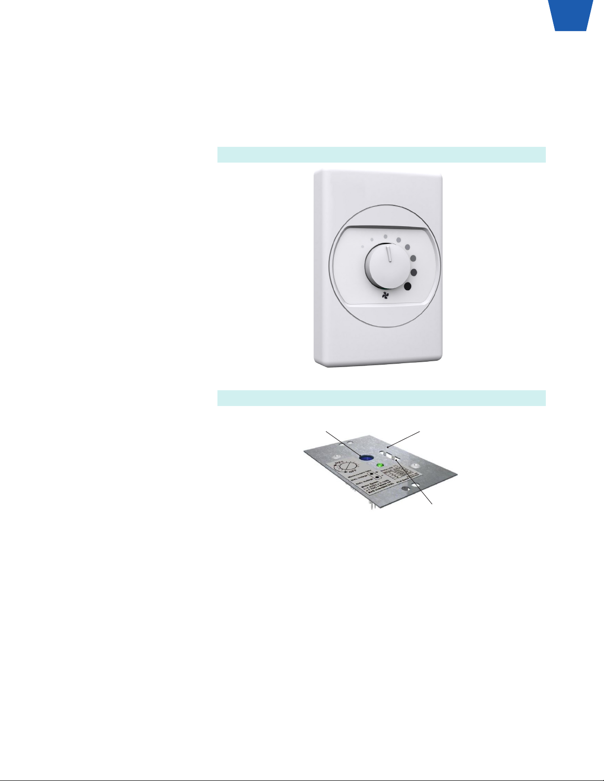
PSC Speed Controller with Wall Kit Option
Step 1: Locate pre-installed electric
box for wall-mounted speed
controller.
Step 2: Wire speed controller
according to wiring diagram. Wall-
mounted speed controller will be
wired in series with the motor.
Step 3: Attach the wall-mounted
controls faceplate to the electrical
box using the screws provided.
Step 4: Wire the unit according
to appropriate wiring diagram. If
Power Cord (PC) option is selected,
simply insert plug end into
electrical socket.
Sample line string: Krown-X-X//I/
SUPPLY/24/48//RSR/HEPA/FC/
PSC/115//R+TMB/FL+ML/PSCSC/
TC/DSW-115/PC-115/ASSP///
WPF/PL-AL/F-AL/PL-B12/F-B12
Step 5: If the unit has an RSR lter
install the lter now, refer to the
lter installation section of this
manual for instructions.
Step 6: Ensure proper voltage is
hooked up to the unit.
Step 7: Proceed to the balancing
section of this manual.
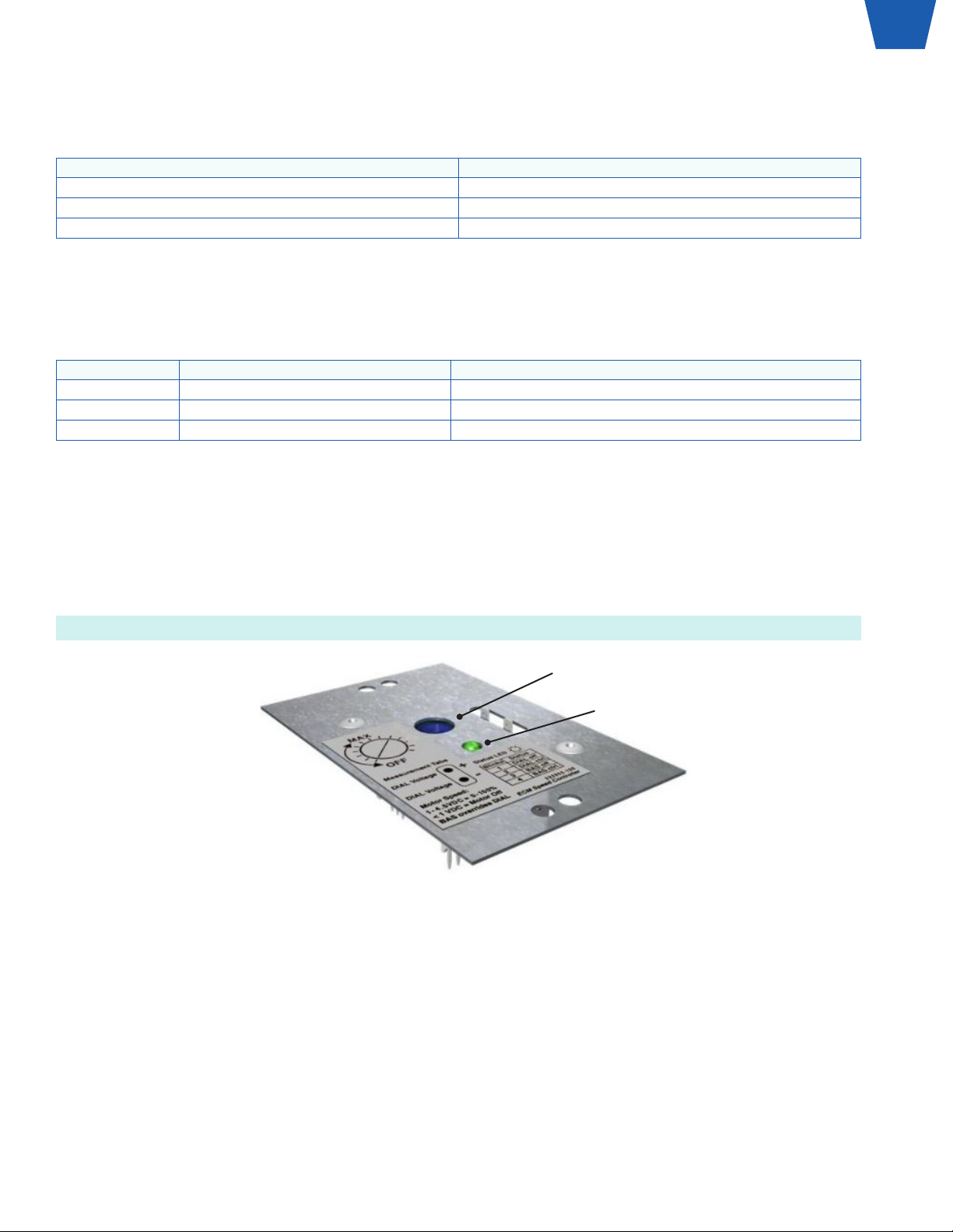
NOTE: Clockwise rotation will
increase airflow, counter-clockwise
rotation will decrease airflow.
NOTE: If unit is ducted, refer to
Technical Note: Balancing Ducted
Units.
For more information visit KeystoneCleanAir.com v001
6
Krown Fan Filter Units | Installation Instructions

ECMSC
Installation
Sample line string: Krown-X-X//I/SUPPLY/24/48//RSR/HEPA/FC/ECM/115/CF/R+TMB//ECMSC/TC/DSW-115//ASSP///
WPF/PL-AL/F-AL/PL-B12/F-B12
Sample line string: KrownCS-X-X//I/ECM/ECMSC/WMSC-30////
Step 1: Wire the unit according to appropriate wiring diagram. If Power Cord (PC) option is selected, simply insert plug end
into electrical socket.
Potentiometer (POT) Measure (+) VDC
Measure (-) VDC
WMSC-30
ECMSC Speed Controller
Step 2: If ECMSC is to be controlled
using analog voltage signal from
BAS (others) or Price WMSC, please
remove ECMSC from control box.
Connect 0-10VDC & COMMON to
BAS SIGNAL & BAS COMMON on
back of ECMSC (make sure to feed
wires through grommet on control
box). Re-fasten ECMSC to control
box.
Step 3: If the unit has an RSR lter
install the lter now, refer to the
lter installation section of this
manual for instructions.
Step 4: Ensure proper Voltage is
hooked up to the unit.
Step 5: Proceed to the following
page to determine the initial test
point voltage (VDC) based on your
scheduled flow rate.
For more information visit KeystoneCleanAir.comv001
7
Krown Fan Filter Units | Installation Instructions

ECMSC Airflow Setpoint
Step 1: Determine initial test point voltage (VDC) based on scheduled flow rate.
To calculate FPM from a CFM value use the equation for the respective unit style and size from the following table.
Size RSR BTR
2x2 CFM/2.30 CFM/3.31
2x3 CFM/3.82 CFM/5.13
2x4 CFM/5.33 CFM/6.95
Supply - Constant Flow – Forward Curve
Velocity 24x24 24x36 24x48
FPM BTR - FC RSR - FC BTR - FC RSR - FC BTR - FC RSR - FC
45-140 VDC =
(CFM-45) ÷ 97
VDC =
(CFM-33) ÷ 67
VDC =
(CFM-76) ÷ 145
VDC =
(CFM-14) ÷ 127
VDC =
(CFM-88) ÷ 198
VDC =
(CFM-67) ÷ 157
Supply - Constant Torque – Forward Curve
Velocity 24x24 24x36 24x48
FPM BTR - FC RSR - FC BTR - FC RSR - FC BTR - FC RSR - FC
45-95 VDC =
(CFM+174) ÷ 309
VDC =
(CFM+168) ÷ 253
VDC =
(CFM+177) ÷ 322
VDC =
(CFM+142) ÷ 273
VDC =
(CFM+139) ÷ 336
VDC =
(CFM+311) ÷ 373
95-140 VDC =
(CFM+19) ÷ 207
VDC =
(CFM+47) ÷ 174
VDC =
(CFM-70) ÷ 197
VDC =
(CFM-79) ÷ 167
VDC =
(CFM-138) ÷ 212
VDC =
(CFM-81) ÷ 190
Supply - Constant Torque – Backward Curve
Velocity 24x36 24x48
FPM BTR - BC RSR - BC BTR - BC RSR - BC
45-140 VDC = (CFM+240) ÷ 450 VDC = (CFM+332) ÷ 415 VDC = (CFM+185) ÷ 459 VDC = (CFM+403) ÷ 514
Reverse Flow - Constant Flow – Forward Curve
Velocity 24x24 24x48
FPM RSR - FC RSR - FC
45-140 VDC = (CFM-24) ÷ 68 VDC = (CFM-61) ÷ 158
Reverse/Exhaust Flow - Constant Torque – Forward Curve
Velocity 24x24 24x48
FPM RSR - FC RSR - FC
45-95 VDC = (CFM+90) ÷ 197 VDC = (CFM+141) ÷ 308
95-140 VDC = (CFM+90) ÷ 197 VDC = (CFM-90) ÷ 196
Supply, 24 x 48 in., RSR, FC Wheel, Constant Torque @ 450cfm
FPM = CFM/5.33 = 450/5.33
FPM = 84
VDC = (CFM+311)/373 = (450+311)/373
VDC = 2.04V
NOTE: The calculated VDC value is intended as a starting point; actual VDC value may differ slightly depending on eld
variables.
For more information visit KeystoneCleanAir.com v001
8
Krown Fan Filter Units | Installation Instructions

Step 2: If using potentiometer/manual adjustment, rotate the potentiometer (POT/DIAL) dial on the outside of the box with a
screwdriver until the test point voltage is achieved.
NOTE: ECM Speed Controllers have 2 modes: manual adjust and BAS (Building Automation System). Standard manual
control outputs are shown below:
Measurement Tab Voltage Motor Control
0 - 1 VDC Off
1 - 4.5 VDC 0-100%
4.5 - 5 VDC 100%
The speed controller will automatically ignore the potentiometer (POT/DIAL) when a BAS signal is detected (BAS Input Signal
>1).
VDC equations are for potentiometer (POT/DIAL) manual adjustment only (0-1 BAS input signal). The VDC equations are
based on a 1-5 Volt scale. The BAS input voltage is a 2-10 VDC scale, and therefore VDC calculated for a given CFM using
the equation must be doubled to achieve that CFM using the BAS input.
BAS Voltage Response Notes
0 - 1 VDC Local control mode using push buttons Local setpoint can be adjusted from 0 - 100% using push buttons
1 - 2 VDC Motor Off Recommended sending a 1.5 VDC signal to command motor off
2 - 10 VDC Modulating Control 2 - 10 VDC modulates motor in accordance with VDC equations
Example: If using a BAS signal, to calculate appropriate starting voltage, rst calculate the VDC (as shown in above example)
VDC = 2.44 V
Then double this value
BAS Input Voltage = VDC*2
BAS Input Voltage = 2.44*2
BAS Input Voltage = 4.88V
Step 3: Wait a few seconds for the ECM motor to adjust its speed and then verify fan airflow with measurements at the unit face
using a flow hood. Adjust the POT/DIAL, or BAS input signal to reach desired airflow as required.
Step 4: Proceed to balancing section of this manual.
Potentiometer/Dial Adjust
Green Status LED must be blinking.
(Code 1 thru 4)
Speed Controller Adjustment
For more information visit KeystoneCleanAir.comv001
9
Krown Fan Filter Units | Installation Instructions

BACnet Flow Controller (BFC)
Installation
Sample line string: Krown-X-X//I/SUPPLY/24/48//RSR/HEPA/FC/ECM/115/CF/R+TMB/BACnet/BFC/TC/DSW-115//
ASSP///WPF/PL-AL/F-AL/PL-B12/F-B12
Step 1: Wire unit according to appropriate wiring diagram. If Power Cord (PC) option is selected, simply insert plug end into
electrical socket.
NOTE: Polarity is important and must be observed. It is also vital that the 24 VAC common side of the transformer be Earth
grounded.
Step 2: Hook up applicable BACnet, and/or local Building Automation System (BAS) according to wiring diagram. Multiple
units can be daisy chained together using optional RJ45 cables. If using BAS or Local Set point, reference the airflow
setpoint section on the next page.
Daisy Chained Krown Fan Filter Units
Step 3: Wire the unit according to the appropriate wiring diagram. If power cord option is selected, simply insert the plug end
into the electric socket.
Sample line string: Krown-X-X//I/SUPPLY/24/48//RSR/HEPA/FC/ECM/115/CF/R+TMB/BACnet/BFC/TC/DSW-115/PC-115/
ASSP///WPF/PL-AL/F-AL/PL-B12/F-B12
Step 4: If the unit has an RSR lter install the lter now, refer to the lter installation section of this manual for instructions.
Step 5: Ensure proper Voltage is hooked up to the unit.
For additional information on BACnet, and the BFC controller, refer to the BACnet Wiring Guidelines, and BFC Manual
available on KeystoneCleanAir.com
BACnet MS/TP to
BACnet IP Router
Krown 1 Krown 2 Krown 3
Krown 30 Krown 4
Network
Connection
IP Router
Webserver Interface
FFU 1
CFM- 312
FIlterHours - 1280
FilterStatus - Clean
ANTEROOM
FFU 2
CFM- 310
FIlterHours - 1125
FilterStatus - Clean
FFU 3
CFM- 312
FIlterHours - 1225
FilterStatus - Replace
FFU 4
CFM- 310
FIlterHours - 1300
FilterStatus - Clean
FFU 5
CFM- 312
FIlterHours - 1430
FilterStatus - Clean
FFU 6
CFM- 315
FIlterHours - 1400
FilterStatus - Replace
FFU 7
CFM- 312
FIlterHours - 1350
FilterStatus - Clean
Webserver
For more information visit KeystoneCleanAir.com v001
10
Krown Fan Filter Units | Installation Instructions

Service Tool
The BFC Service Tool can be used for cases with limited access to the control box. The service tool connects to the RJ12
port on the BFC board to allow full control up to 6 feet away from the control panel.
Sample line string: KrownCS-X-X//I/ECM/BFC/BFC-ST//250002-600
For more information visit KeystoneCleanAir.comv001
11
Krown Fan Filter Units | Installation Instructions

BFC Airflow Setpoint
Step 1: Determine if BFC will be controlled using local control, BAS analog voltage signal, or BACnet. The control mode can
be conrmed by observing the cycling status readout on the LCD.
NOTE: The control hierarchy is BACnet > BAS > Local. The control mode is based on the highest level of control provided.
Step 2: For Local or BACnet control, determine the setpoint from the appropriate airflow formula for your model in the tables
below.
If BFC is being controlled by BAS analog voltage signal, refer to "ECMSC Airflow Setpoint" section for proper input voltage
(Note this will be 2X the VDC value shown in the tables).
Set-point (ECM%) ranges from 0% - 100%
To calculate FPM from a CFM value use the equation for the respective unit style and size from the following table.
RSR BTR
2x2 CFM/2.30 CFM/3.31
2x3 CFM/3.82 CFM/5.13
2x4 CFM/5.33 CFM/6.95
Supply - Constant Flow - Forward Curve
Velocity 24x24 24x36 24x48
FPM BTR - FC RSR - FC BTR - FC RSR - FC BTR - FC RSR - FC
45-140 ECM% =
(CFM ÷ 3.40) - 42
ECM% =
(CFM ÷ 2.35) - 43
ECM% =
(CFM ÷ 5.08) - 44
ECM% =
(CFM ÷ 4.45) - 32
ECM% =
(CFM ÷ 6.93) - 42
ECM% =
(CFM ÷ 5.50) - 41
Supply - Constant Torque - Forward Curve
Velocity 24x24 24x36 24x48
FPM BTR - FC RSR - FC BTR - FC RSR - FC BTR - FC RSR - FC
45-95 ECM% =
(CFM ÷ 10.82) - 12
ECM% =
(CFM ÷ 8.86) - 10
ECM% =
(CFM ÷ 11.27) - 13
ECM% =
(CFM ÷ 9.56) - 14
ECM% =
(CFM ÷ 11.76) - 17
ECM% =
(CFM ÷ 13.06) - 5
95-140 ECM% =
(CFM ÷ 7.25) - 26
ECM% =
(CFM ÷ 6.09) - 21
ECM% =
(CFM ÷ 6.90) - 39
ECM% =
(CFM ÷ 5.85) - 42
ECM% =
(CFM ÷ 7.42) - 47
ECM% =
(CFM ÷ 6.65) - 41
Supply - Constant Torque - Backward Curve
Velocity 24x36 24x48
FPM BTR - BC RSR - BC BTR - BC RSR - BC
45-140 ECM% = (CFM ÷ 15.75) - 13 ECM% = (CFM ÷ 14.53) - 6 ECM% = (CFM ÷ 16.07) - 17 ECM% = (CFM ÷ 17.99) - 6
Reverse/Exhaust Flow - Constant Flow - Forward Curve
Velocity 24x24 24x48
FPM RSR - FC RSR - FC
45-140 ECM% = (CFM ÷ 2.38) - 39 ECM% = (CFM ÷ 5.53) - 40
Reverse/Exhaust Flow - Constant Torque - Forward Curve
Velocity 24x24 24x48
FPM RSR - FC RSR - FC
45-95 ECM% = (CFM ÷ 6.90) - 16 ECM% = (CFM ÷ 10.78) - 15
95-140 ECM% = (CFM ÷ 6.90) - 16 ECM% = (CFM ÷ 6.86) - 42
Supply, 24 x 48 in., RSR, FC Wheel, Constant Torque @ 550cfm
FPM = CFM/5.33 = 550/5.33
FPM = 103
ECM% = (CFM/6.65)-41 = (550/6.65)-41
ECM% = 42%
NOTE: The calculated ECM% value is intended as a starting point; actual ECM% value may differ slightly depending on eld
variables.
For more information visit KeystoneCleanAir.com v001
12
Krown Fan Filter Units | Installation Instructions

Step 3: For local control, adjust at the speed controller using the up and down arrows. For BACnet control, adjust point "AO3
- ECM Setpoint" on Front End System.
Step 4: For BAS analog voltage control, ensure correct voltage is applied to AI1 & COM based on the VDC equations provided
in the tables. Also refer to table below for BAS control responses.
BAS Voltage Response Notes
0 - 1 VDC Local control mode using push buttons Local setpoint can be adjusted from 0 - 100% using push buttons
1 - 2 VDC Motor Off Recommended sending a 1.5 VDC signal to command motor off
2 - 10 VDC Modulating Control 2 - 10 VDC modulates motor in accordance with VDC equations
The VDC equations are based on a 1-5 Volt scale. The BAS input voltage is a 2-10 VDC scale, and therefore VDC calculated
for a given CFM using the equations must be doubled to achieve that CFM using the BAS input.
NOTE: The calculated ECM setpoint is a starting point; actual value may differ slightly depending on eld variables.
NOTE: The BAS signal will override the local setpoint using a remote 0 – 10 VDC signal. If the BAS signal drops below 1 VDC
local control (via the up/down buttons) is restored.
Step 5: Wait a few seconds for the ECM motor to adjust its speed and then verify fan airflow with measurements at the
supply outlets using a flow hood. Adjust voltage to reach desired airflow as required.
Step 6: Proceed to Balancing section of this manual.
For more information visit KeystoneCleanAir.comv001
13
Krown Fan Filter Units | Installation Instructions

Filter Installation
Room Side Replaceable Filter (RSR)
Sample line string: Krown-X-X//I/SUPPLY/24/48//RSR/HEPA/FC/ECM/115/CF/R+TMB/BACnet/BFC/TC/DSW-115//
ASSP///WPF/PL-AL/F-AL/PL-B12/F-B12
Please refer to the Vangaurd Room Side Replaceable Filter (RSR) Quick Start Guide.
RSR
BTR
Bench Top Replaceable Filter (BTR)
Sample line string: Krown-X-X//I/24/48/BTR/FC/ECM/115/10//CF//HEPA//BFC////DSW-115//PC-115//TMB/ASSP///
FL+ML+BACnet/// WPFH/PL-AL///PL-B12/
Please refer to the Vangaurd Bench Top Replaceable Filter (BTR) Quick Start Guide.
For more information visit KeystoneCleanAir.com v001
14
Krown Fan Filter Units | Installation Instructions

Accessories
Aerosol Sample Static Pressure Port (ASSP)
Sample line string: Krown-X-X//I/SUPPLY/24/48//
RSR/HEPA/FC/ECM/115/CF/R+TMB/BACnet/BFC/TC/
DSW-115/PC-115/ASSP/INJ//WPF/PL-AL/F-AL/PL-
B12/F-B12
Every Krown Fan Filter Unit from Keystone is supplied
with an aerosol sample/static pressure port.
The ASSP is a ¼” port used for measuring plenum static
pressure as well as sampling aerosol concentrations
above the lter.
On the Krown Fan Filter Unit with BTR lter there are two
ports on the center strip of the lter than can function as
the ASSP, however if the LED indicator option has been
selected, one port will be used for the LED installation.
ASSP on BTR unit
ASSP & INJ RSR unit
Optional Aerosol Injection Port (INJ)
Sample line string: Krown-X-X//I/SUPPLY/24/48//
RSR/HEPA/FC/ECM/115/CF/R+TMB/BACnet/BFC/TC/
DSW-115/PC-115/ASSP/INJ//WPF/PL-AL/F-AL/PL-
B12/F-B12
The Krown Fan Filter Unit with RSR lter can be ordered
with an optional aerosol injection port for easier
commissioning.
The INJ is a barbed port for 1/2" inner diameter tubing,
used to inject aerosol above the lter for aerosol testing.
For instructions on use of the ASSP and INJ, please refer
to the INJ Aerosol Injection Port User Manual.
For more information visit KeystoneCleanAir.comv001
15
Krown Fan Filter Units | Installation Instructions

Filter/Motor Indicator LED (ML/FL) - PSC Units
Sample line string: Krown-X-X//I/SUPPLY/24/48//RSR/HEPA/FC/PSC/115//R+TMB/FL+ML/PSC-WK/TC/DSW-115//ASSP///
WPF/PL-AL/F-AL/PL-B12/F-B12
LED Installation (BTR Units only)
Step 1: Take LED cable assembly out of Krown-X-X Plenum.
Step 2: Remove well nut in center port of BTR lter.
Step 3: Remove threaded standoff and lock washer from LED cable assembly.
Step 4: Thread cable through static pressure port on face of BTR lter.
NOTE: It is recommended to rest the lter frame on 2x4 lumber to protect the LED light from breaking.
Threaded Standoff
Lock Washer
Rubber Washer
Metal Washer
LED
LED Threaded Standoff Filter Position for LED Installation
Static Pressure PortCable Assembly
For more information visit KeystoneCleanAir.com v001
16
Krown Fan Filter Units | Installation Instructions

Step 5: Put lock washer and
threaded standoff back on cable
and tighten to LED.
Step 6: With two (2) people holding
the unit, pull cable back through
plenum until plenum can rest on
top of lter.
Step 7: Install the lter, refer to the
lter installation section of this
manual.
Step 8: Refer to wiring diagram
(located in control box) to connect
LED leads to terminal block.
NOTE: If unit has BFC speed
controller, LED leads will need to
be connected to the BFC controller
instead of the terminal block.
BTR Face Installed LED
Threaded Standoff Through Filter Channel
Cable Assembly
For more information visit KeystoneCleanAir.comv001
17
Krown Fan Filter Units | Installation Instructions

LED Operation
Option Code LED Color Action Notes
Filter LED FL
Green None Indicates normal operation until lter pressure drop exceeds
calibrated pressure drop (factory set at 1.5x clean lter pressure).
Yellow Change Filter Indicates lter pressure drop has exceeded calbirated setting (factory
set at 1.5x clean lter pressure.
Motor LED ML
Green None Indicates normal motor operation when the static pressure is above 0.1"
w.g.
Red Troubleshoot Motor Indicates motor is not in operation, and that unit static pressure is below
0.1" w.g.
Calibration
Filter LED will come factory set to activate at the pressure drops listed in the Table below.
Pressure @ 90fpm [in w.g.] 1.5x Clean Filter [in w.g.]
0.4 0.6
If different set points are desired, they can be adjusted as follows:
Pressure Switch Adjustment Screw
Step 1: Remove Loctite from
adjustment screw hole.
For more information visit KeystoneCleanAir.com v001
18
Krown Fan Filter Units | Installation Instructions

Step 2: Calculate number of turns
required based on difference
between factory set point and
desired set point using the
following chart.
Example:
HEPA lter with desired set point of
0.9 in w.g.
Number of turns at 0.9 in w.g. = 4
Number of turns at factory set
point of 0.6 in w.g. = 2.2
Number of turns to eld set = 4 –
2.2 = 1.8 (approximately)
NOTE: Maximum available pressure
setting is 1.0” w.g. Do not exceed 4
½ turns (total).
Step 3: Turn screw clockwise the
number of turns calculated above.
You will need a 1.5mm hex Allen
wrench
Step 4: To check lter pressure
set point and/or to ne tune, insert
Magnehelic gauge into the static
pressure port (located along knife
edge of diffuser – diffuser face
must be removed to access).
Step 5: Using an obstruction (piece
of cardboard or equivalent), slowly
increasing pressure on the unit by
blocking off more and more of the
diffuser face until the LED turns
from green to yellow.
Step 6: Take pressure
measurement at point the LED
changed color and rotate the
adjustment screw until desired
pressure set point is reached.
Set Point in Inches w.g.
Turns of Set Point Adjustment Screw
(from starting point at 0.25” w.g.)
1.00
0.90
0.80
0.70
0.60
0.50
0.40
0.30
0.20
0.10
0.00
Table 2. Set Point Adjustment
Turns of Set Point Adjustment Screw
(from starting point at 0.25” w.g.)
Set Point in inches w.g.
0 1 2 3 4 5
1.00
0.90
0.80
0.70
0.60
0.50
0.40
0.30
0.20
0.10
0.00
0 1 2 3 4 5
RSR Filter LED Set Point Adjustment
For more information visit KeystoneCleanAir.comv001
19
Krown Fan Filter Units | Installation Instructions

Filter/Motor Indicator LED (ML/FL) - ECM Units
Sample line string: Krown-X-X//I/SUPPLY/24/48//RSR/HEPA/FC/ECM/115//R+TMB/FL+ML+BACnet/BFC/TC/DSW-115//
ASSP///WPF/PL-AL/F-AL/PL-B12/F-B12
LED Operation
LED Color Unit Status* Action Notes
Green Normal None Indicates normal operation until pressure drop exceeds calibrated pressure drop
(factory set a 1.5x clean lter pressure).
Yellow Ftr Loaded Change or calibrate lter Indicates lter pressure drop has exceeded calibrated setting (factory set at
1.5x the clean lter pressure).
Red Off Adjust setpoint / check
control mode
Indicates motor setpoint is 0%. If alternate setpoint is expected please check
control mode.
Blinking Red Low Pressure Troubleshoot motor Indicates unit pressure is below 0.1 in. w.g. and motor setpoint is above 0%.
*Unit status is shown on BFC LCD screen or as BACnet point: "MV1 - Unit Status"
Integrated LED Lighting (Krown-L)
For details on installation and wiring please refer to the RDC Remote Driver Cabinet Manual on KeystoneCleanAir.com on
KeystoneCleanAir.com.
.Krown-L
For more information visit KeystoneCleanAir.com v001
20
Krown Fan Filter Units | Service Instructions
Table of contents
Other Keystone Water Filtration System manuals