Adjust backrest so it appears centered between the two
back canes and both clamps are set at the same height
on both sides. Using a tape measure or level is
recommended to ensure both sides are set up equally. At
this point you can also adjust the angle by tilting the
backrest shell forward or backward to ensure uniform
tilting on both sides.
A
BDEF
1
Fitting Adjustments (User Present)
1” - 2”
A
1”
BC
>0-2” Narrower than back - Assemble in Inner Slots
0-2” Wider than back - Assemble in Outer Slots
Any other size difference - Do not assemble
A
B
C
C
D
>0-2” Narrower than back - Assemble in Inner Slots
0-2” Wider than back - Assemble in Outer Slots
Any other size difference - Do not assemble
BC
A
6
5
1”
A
BC
2
3
1” - 2”
No interference at
clamp locations
No interference at
clamp locations
A
A
A
A
A
BC
A
1
A
1”
BC
>0-2” Narrower than back - Assemble in Inner Slots
0-2” Wider than back - Assemble in Outer Slots
Any other size difference - Do not assemble
1”
>0-2” Narrower than back - Assemble in Inner Slots
0-2” Wider than back - Assemble in Outer Slots
Any other size difference - Do not assemble
BC
A
A
1”
BC
>0-2” Narrower than back - Assemble in Inner Slots
0-2” Wider than back - Assemble in Outer Slots
Any other size difference - Do not assemble
1”
>0-2” Narrower than back - Assemble in Inner Slots
0-2” Wider than back - Assemble in Outer Slots
Any other size difference - Do not assemble
BC
A
Determine installation slots based on configuration.
A x i o m
Back
W i d t h
Inne r Sl o t s O ut e r Sl o t s
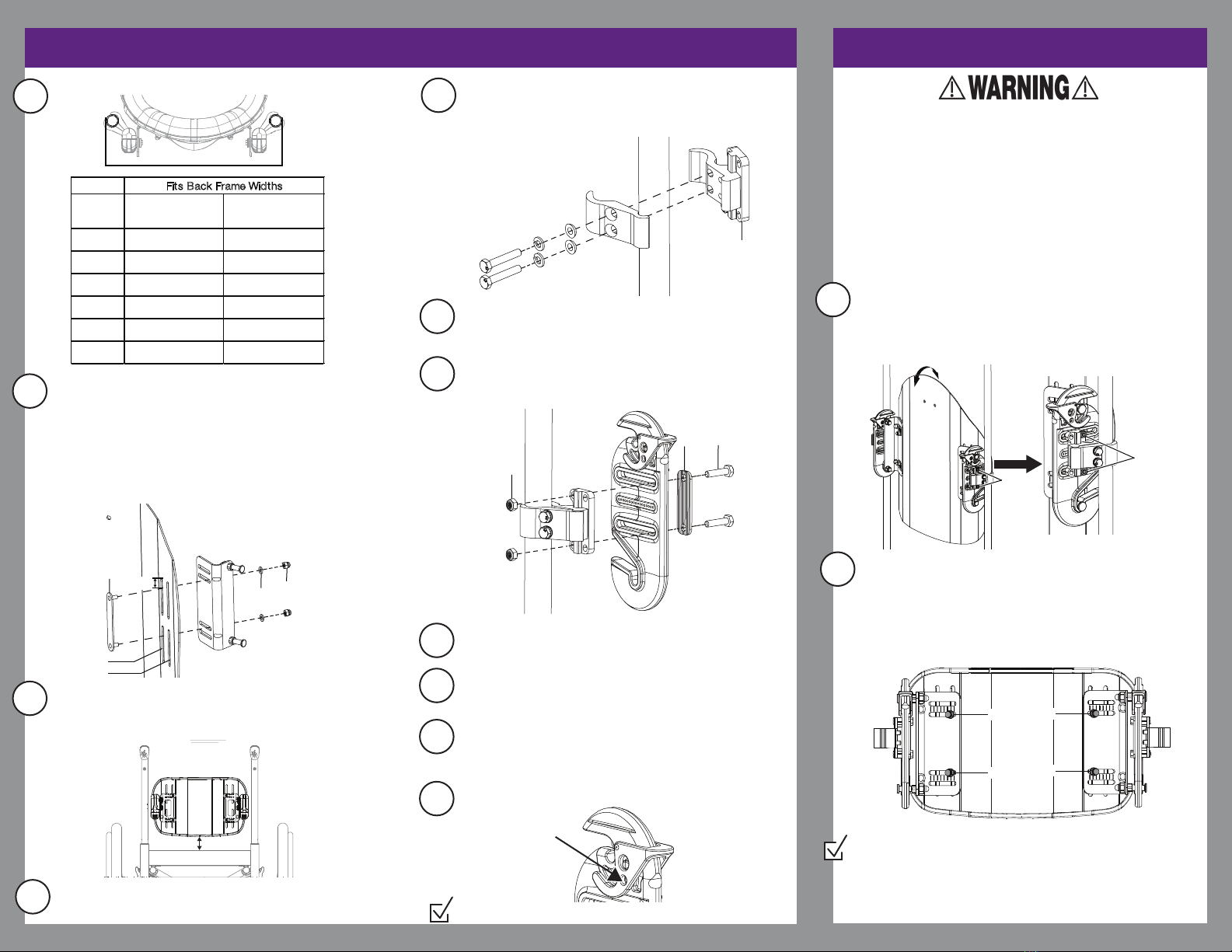
12" (30.5cm) 11" (28.0cm) 12" -14" (30.5cm -35.5cm)
14" (35.5cm) 12" -13" (30.5cm -33.0cm) 14" -16" (35.5cm -40.5cm)
16" (40.5cm) 14" -15" (35.5cm -38.0cm) 16" -18" (40.5cm -45.5cm)
18" (45.5cm) 16" - 17" (40.5cm - 43.0cm) 18" - 20" (45.5cm - 50.5cm)
20" (51.0cm) 18" -19" (46.0cm -48.5cm) 20" -22" (50.5cm -55.5cm)
22" (56.0cm) 20" -21" (51.0cm -53.5cm) 22" -24" (56.0cm -61.0cm)
Fits Back Frame Widths
Remove backrest shell from cover. Install the backrest
bracket to the shell with the stud plate (A), two washers
(B) and two dome nuts (C). Install so stud plates are 1”
from the top of each bracket slot. Loosely tighten
hardware. Repeat on opposite side. Note: Ensure
lanyard is at the top of the plate (Not seen below as it is
mounted on the inside of the bracket on the top
connecting rod hardware).
A
BC
>0-2” Narrower than back -
0-2” Wider than back - Ass
Any other size difference -
>0-2” Narrower than back
0-2” Wider than back - Ass
Any other size difference -
BC
A
1”
A
BC
B
B
C
DE
” -
”
e at
ions
No
cla
1” - 2”
Hold the backrest shell against the chair at approximate height
desired. Find a back cane location that can accomodate the
clamp near the center of the slots on the backrest bracket.
Typically the backrest will rest 1-2” above the cushion.
4
Loosely assemble the clamps onto the back canes at the
desired location talked about in step 3. Bolts should thread
inwards from the outside of the chair. Tighten clamp enough
so it stays in place and repeat on opposite side.
Perform Check, see Check Section in next section.
General Setup (Before Delivery)
A
A
A
A
Perform Check -
a. Tighten all fasteners completely and assure that the hardware
does not move out of the adjusted position under the load
of the user.
b. Verify the back releases and latches easily.
c. Lift the backrest up by the strap and ensure it stays locked in.
Inner Slot
Outer Slot
1/2”
WARNING: IT MAY BE POSSIBLE TO ADJUST THE FINAL POSITION
OF THE AXIOM BACK WITH AN END USER SEATED IN HIS
WHEELCHAIR. THIS REQUIRES THAT THE END USER BE ABLE TO
SIT IN A STABLE POSITION WITHOUT THE USE OF THE BACKREST.
IT MAY ALSO BE POSSIBLE IF THERE ARE PEOPLE WHO CAN
SUPPORT THE END USER DURING ADJUSTMENT, THIS SHOULD
BE VERIFIED BY A CLINICIAN TRAINED TO MAKE THAT
DETERMINATION. ALWAYS MAKE SURE THE WHEELCHAIR WHEEL
LOCKS AND ANTI-TIPS ARE SET AND LOCKED. IF THESE
CONDITIONS CANNOT BE MET, THE END USER SHOULD
TRANSFER FROM THE WHEELCHAIR BEFORE MAKING
ADJUSTMENTS. FAILURE TO TAKE THESE PRECAUTIONS MAY
RESULT IN A FALL AND THE POTENTIAL FOR A SERIOUS INJURY.
A
1
A
A
A
A
A
To adjust the backrest up or down, loosen the backrest
bracket hardware (A) and move the assembly up or down.
If more range is needed, the hardware can be removed
and reinstalled into the other backrest bracket slots. Ensure
both sides are set in the identical alignment guide positions
in the backrest bracket. Retighten hardware once desired
configuration is achieved.
2
To adjust the angle of the backrest, loosen the hardware
attaching the clamp to the receiver on both sides of
backrest. Tilt the backrest shell forward or backward to
ensure uniform tilting on both sides. Tighten hardware
once desired configuration is achieved.
A
DE
B
B
C
DE
e at
ions
No
cl
1” - 2”
Determine the clamp orientation, forward or rear facing and
the clamp bracket (Step 5 Image:A) orientation and hole use
(See Clamp Positioning Chart on the outside of this document).
Assure that the assemblies on each side are the set at the
same height and that the clamp brackets (Step 5 Image:A)
are parallel to each other and set in the same orientation.
A
7
Install backrest mount to clamp assembly with two bolts (C),
saddle (B) and two nuts (A) using a 10mm wrench. Repeat on
opposite side.
10
8
Install the backrest to the clamp and backrest mount assembly.
9
Adjust the backrest height to desired height by moving the
backrest up or down along the backrest bracket hardware.
See Step 2 of custom adjustments for imagery.
Adjust the backrest depth and angle to desired position by
moving the backrest uniformly along the hardware attaching the
clamp to the receiver on both sides. See Step 1 of Custom
Adjustments for imagery.
11
Install the lock pin.
1” - 2”
A
BC
A
A


