5
For more details, please refer to your Owner’s Manual.
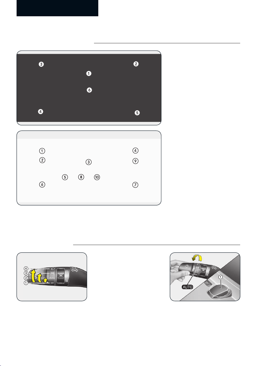
Windows / Wipers and washers
Windows [4] Wipers and washers [4]
A: Wiper speed control (front)
1 2/HI – High wiper speed
2 1/LO – Low wiper speed
3 ---/INT – Intermittent wipe
AUTO* – Automatic control wipe
4 O/OFF – Off
5 /1X/MIST – Single wipe
B: Intermittent control wipe time adjustment
C: Wash with brief wipes (front)*
D: Rear wiper/washer control*
6 2/HI/ – Continuous wipe
7 1/LO/ /ON – Intermittent wipe
8 O/OFF – Off
E: Wash with brief wipes (rear)
1 Driver’s door power window switch
2 Front passenger’s door power window switch
3 Rear door (left) power window switch*
4 Rear door (right) power window switch*
5 Automatic power window up*/down*
(Driver’s window)
6 Power window lock switch*
❈ In cold and wet climates, power windows may
not work properly due to freezing conditions.
Reverse Parking Distance Warning (PDW)*
Reverse parking distance
warning will alert the driver
by warning indicator or sound
if person, animal, or object in
certain range is detected from
the rear ultrasonic sensor (1)
when the vehicle is moving
reverse at low speeds.
Reverse parking distance
warning settings
• Reverse parking distance
warning activates when the
gear is R (Reverse) position.
• Reverse parking distance
warning assists the driver
during reverse movement of
the vehicle by chiming if any
people, animal, or object is
sensed when the vehicle speed
is below 10km/h (6mph).
• When people, animal, or
objects are detected, it is
displayed on the cluster with
an audible warning.
• When more than two people,
animal, or objects are detected
at the same time, the closest
one will be alerted with an
audible warning.
*: if equipped
Front Rear*
Rear ultrasonic sensors
(Type A)
Rear ultrasonic sensors
(Type B)
Types of warning sound Indicator*
When an object is
120 cm to 60 cm (47 in.
to 24 in.) from the rear
bumper: Buzzer beeps
intermittently.
When an object is
60 cm to 30 cm (24 in.
to 12 in.) from the rear
bumper: Buzzer beeps
more frequently.
When an object is
within 30 cm (12 in.)
of the rear bumper:
Buzzer sounds
continuously.