KIESELMANN ASi-Bus ES/ABSL 5630 010-000 Series User manual


Operating instructions - Translation of the original -
25.4.12
KIESELMANN GmbH
Paul-Kieselmann-Str.4-10
D - 75438 Knittlingen
+49 (0) 7043 371-0Fax: +49 (0) 7043 371-125
www.kieselmann.desales@kieselmann.de
Control head ASi-Bus ES/ABSL
5630 xxx 010-000
with platine V4.x
for Double seat valve
Single seat valve
Butterfly valve
Ball valve

25.4.12
Operation instructions: Control head 5630xxx010-000
ASi-Bus ES/ABSL
2
1. List of contents ..............................................................................................................2
2. Information for your safety............................................................................................. 3
3. Marking of safety instructions in the operating manual ................................................. 3
4. Variants of control heads ASi-Bus ES/ABSL................................................................. 4
4.1 Double seat valve (pneum. Lifting valve) ............................................................ 4
4.2 Single seat valve (pneum. Lifting valve).............................................................. 4
4.3 Butterfly valve / Ball valve (pneum. Rotary valve).............................................. 4
5. Safety instructions........................................................................................................ 5
5.1 Field of application .............................................................................................. 5
5.2 General safety instructions.................................................................................. 5
5.3 General notes ..................................................................................................... 5
6. Function ........................................................................................................................ 5
6.1 Description of function ........................................................................................ 5
7. Maintenance.................................................................................................................. 5
8. Installation informations................................................................................................. 5
8.1 Installation instructions........................................................................................ 5
9. Initial operation .............................................................................................................. 6
10. Power supply / valve control.......................................................................................... 6
10.1 Standard variant.................................................................................................. 6
10.2 ES variant (plug P5)........................................................................................... 6
10.3 Switch-over Standard / ES (selector switch E).................................................... 6
10.4 JTAG Interface (plug P1) ................................................................................... 6
10.5 External inputs 1 (plug P4) and 2 (plug P3) ........................................................ 6
10.6 Valve interface (plug F)..................................................................................... 6
11. Electrical installation......................................................................................................7
11.1 Electrical connection of the control head ............................................................ 7
11.2 Terminal pin assignment ..................................................................................... 7
11.3 LED Indication of slave status / Selector switch (D)........................................... 7
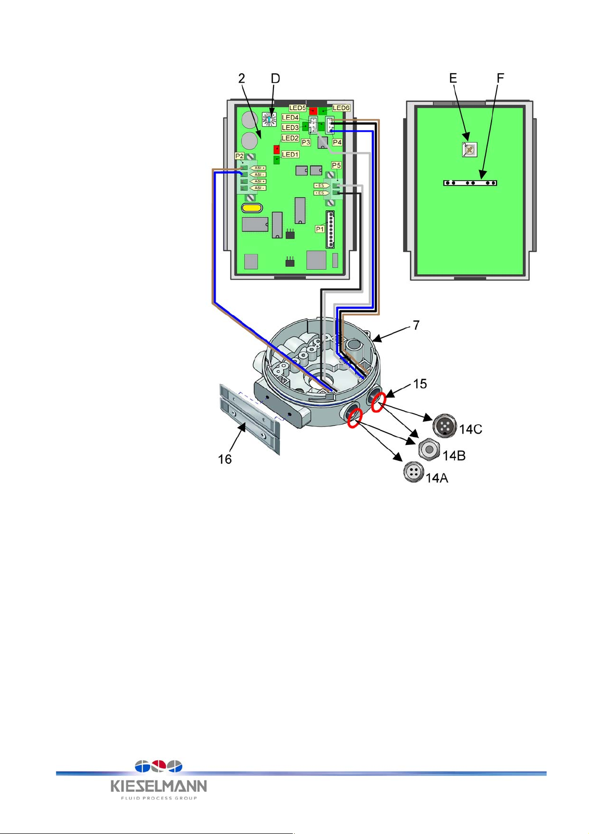
11.4 Electrical connection design of control head ASi-Bus ES/ABSL......................... 8
12. Position control and position indication ......................................................................... 9
12.1 Lifting valve ......................................................................................................... 9
12.2 Rotary valve ...................................................................................................... 10
13. Electrical and pneumatical piloting ASi-Bus ES/ABSL................................................ 11
13.1 Valve piloting - Double seat valve ..................................................................... 11
13.2 Valve piloting - Lifting valve............................................................................... 12
13.3 Valve piloting - Rotary valve.............................................................................. 13
13.4 Bit-assignment external input............................................................................ 13
14. Demontage und Montage............................................................................................ 14
14.1 Disassembly...................................................................................................... 14
14.2 Assembly .......................................................................................................... 14
15. Spare parts list ............................................................................................................ 15
16. Technical data ............................................................................................................. 16
17. Fault clearance............................................................................................................ 16
1. List of contents

25.4.12
Operation instructions: Control head 5630xxx010-000
ASi-Bus ES/ABSL
3
2. Information for your safety
We are pleased that you have decided for a high-class KIESELMANN product. With correct application
and adequate maintenance, our products provide long time and reliable operation.
Before installation and initiation, please carefully read this instruction manual and the security advices
contained in it. This guarantees reliable and safe operation of this product and your plant respectively.
Please note that an incorrect application of the process components may lead to great material damages
and personal injury.
In case of damages caused by non observance of this instruction manual, incorrect initiation,
handling or external interference, guarantee and warranty will lapse!
Our products are produced, mounted and tested with high diligence. However, if there is still a reason
for complaint, we will naturally try to give you entire satisfaction within the scope of our warranty. We will
be at your disposal also after expiration of the warranty. In addition, you will also find all necessary instruc-
tions and spare part data for maintenance in this instruction manual. If you don't want to carry out the main-
tenance by yourself, our KIESELMANN service team will naturally be at your disposal.
3. Marking of safety instructions in the operating manual
Hintsareavailableinthechapter"safetyinstructions"ordirectlybeforetherespectiveoperationinstruction.
The hints are highlighted with a danger symbol and a signal word. Texts beside these symbols have to
be read and adhered to by all means. Please continue with the text and with the handling at the valve only
afterwards.
Symbol Signal word Meaning
DANGER Imminent danger which may cause
severe personal injury or death.
ATTENTION
Dangerous situation which may
cause slight personal injury or
material damages.
NOTE
Marks application hints and other
information which is particularly
useful.

25.4.12
Operation instructions: Control head 5630xxx010-000
ASi-Bus ES/ABSL
4
4. Variants of control heads ASi-Bus ES/ABSL
4.1 Double seat valve (pneum. Lifting valve)
4.2 Single seat valve (pneum. Lifting valve)
4.3 Butterfly valve / Ball valve (pneum. Rotary valve)
Valve function Electrical connection Solenoid valves Article No.
without lifts
Plug M12 4-pin
Socket plug M12 5-pin
1 solenoid valve 5630 201 010–000
with upper seat lift 2 solenoid valves 5630 202 010–000
with lower seat lift 2 solenoid valves 5630 206 010–000
with upper + lower seat lift 3 solenoid valves 5630 203 010–000
Valve function Electrical connection Solenoid valves Article No.
air open / spring closed
air closed / spring open
Plug M12 4-pin
Socket plug M12 5-pin
1 solenoid valve 5630 501 010–000
air closed / air open 2 solenoid valves 5630 502 010–000
Valve function Electrical connection Solenoid valves Article No.
air open / spring closed
air closed / spring open
Plug M12 4-pin
Socket plug M12 5-pin
1 solenoid valve 5630 801 010–000
air closed / air open 2 solenoid valves 5630 802 010–000

25.4.12
Operation instructions: Control head 5630xxx010-000
ASi-Bus ES/ABSL
5
5. Safety instructions
5.1 Field of application
The control heads are used to pilot valves of production systems of the beverage and foodstuff industry,
pharmaceutical industry, bio-technology, and chemical industry.
They contain the complete actuator, sensory, and electronic technology for connection and integration
to up-dated and efficient control systems.
5.2 General safety instructions
5.3 General notes
6. Function
The control head has been constructed in a modular system. Depending on the performance the pneu-
matic (three solenoid valves at maximum) and the electric control module with 2 position response syn-
chros (hall sensors on the board) have been integrated into the control head.
6.1 Description of function
The valve positions are displayed electrically (DUO - LED) and directly at the control head. The valve
positions "OPEN" and "CLOSED" are in addition displayed mechanically.
For robust operating conditions we recommend the use of the option stainless cab.
A pressure relieve valve serves as a pressure reduction in case of air leakages. The electric connection
is carried out via a electrical connection plug or a flat cable adapter at the control head. As a protection
against external influences, the cab can be leaded (only possible in the version - plastic cab)
7. Maintenance
The control head is maintenance-free. However, it is recommended to check the density of the air con-
nections at fixed intervals, The air pressure escapes at air leakages through a pressure control valve
into the open air.
8. Installation informations
8.1 Installation instructions
Generally the assembly and disassembly of the control head must occur de-energized.
ATTENTION
• To avoid danger and damage, the fitting must be used in accordance with the safety instructions
and technical data contained in the operating instructions.
DANGER
• The personnel responsible for the service and maintenance is instructed to carefully read and follow
this operating manual and to maintain the prescribed technical data.
The manufacturer will not be liable for any damages caused by improper use or handling.
• Make sure that the prevailing requirements of accident prevention and safety for electrical appli-
ances are complied with during the maintenance and repair works.
•
Never carry out electrical connections while the system is under energized.
ATTENTION
• Danger of injury by destruction of the housing cap, if the spindle cap is screwed in into the pulse generator
not completely (see Fig.2 /Page9). The spindle cap must be screwed in up to metallic limit stop on the
pulse generator.
NOTE
•
All data are in line with the current state of development. Subject to change as a result of technical
progress.

25.4.12
Operation instructions: Control head 5630xxx010-000
ASi-Bus ES/ABSL
6
9. Initial operation
•
Adjust the valve functions at the valve selector switch (D).
(Tab. 2, page 7)
•
Connect power supply.
(see “Electrical installation” on page 7)
•
Connect the control air pipe Ø 6x1 to the connection (17).
(Fig.7 /Page14)
•
Connect the compressed-air pipe Ø 6x1 to the connection (11).
(Fig.7 /Page14)
•
Check the pneumatic components for air leakages.
•
Check the valve functions by activating manually the solenoid valves (20a). The manual activator is
provided as slide switch at the front side of the solenoid valves (20a).
10. Power supply / valve control
10.1 Standard variant
The power supply to the control board is taken from the 30V supply that lies close to the bus. All extra
components that can be switched on the control board are supplied directly via the bus and/or internally
generated voltage 24V DC. The valves are also controlled directly on the control board. Transient
diodes protect the electronics against voltages that are too high and peak voltages.
10.2 ES variant (plug P5)
In the ES variant, an additional 24V power supply for the solenoid valve is required. This voltage is fed
into the control board via a separate plug (P5). The internal power supply of the solenoid valves is then
cut off over the switch (E).
10.3 Switch-over Standard / ES (selector switch E)
In the back of the committee there is a counter with 2 positions. With this counter can be put whether
the committee should be pursued in the standard way or in the ES way. Encoding takes place from the
Kieselmann society. The counter is sealed after the choice. A suitable mark of the type of the manage-
ment is indicated on the frame.
10.4 JTAG Interface (plug P1)
The control board is equipped with a JTAG interface that allows the processor to be equipped with new
firmware at any time. Via this interface, the firmware on the control board can be changed easily and
at any time with a handheld programmer. Other solutions with the existing hardware are then easier to
realise.
10.5 External inputs 1 (plug P4) and 2 (plug P3)
There are two input channels for processing external signals that can be brought onto the control board
by inductive or capacitive sensors. The connectable sensors are also supplied via the control board
with 24V.
10.6 Valve interface (plug F)
The interface for the connection of a maximum of 3 solenoid valves is integrated on the control board.
The solenoid valves are inserted with the air distribution block onto the control board and screwed as
one complete unit within the TOP.

25.4.12
Operation instructions: Control head 5630xxx010-000
ASi-Bus ES/ABSL
7
11. Electrical installation
11.1 Electrical connection of the control head
➣Plug 4-pin (14A)
•
The electrical connection of the ASI-Bus control head occurs through a plug 4-pin
(LUMBERG PRSFM4). (see Tab.1 Pin assignment)
➣Socket plug 5-pin (14C)
•
The electrical connection of the ASI-Bus control head occurs through a plug socket 5-pin (LUMBERG
PRKFM5). (see Tab.1 Pin assignment)
➣Electrical connection on the board
•
The installation of power cables from the plugs to the board is carried out by the manufacturer.
11.2 Terminal pin assignment
Tab. 1
11.3 LED Indication of slave status / Selector switch (D)
Tab. 2
Plug
(14A)
Pin No. Colour code Assignment Plug
P2 P5
1braun
brown Inputsignal Bus ASI (+)
2weiß
white ext. voltage ES 24 Volt (-)
3blau
blue Inputsignal Bus ASI (-)
4schwarz
black ext. voltage ES 24 Volt (+)
Socket plug Pin No. Colour code Assignment Plug
(14C) P3 P4
1braun
brown 24 Volt (+)
2weiß
white Sensor control line 2
3blau
blue GND
4schwarz
black Sensor control line 1
5grün/gelb
green/yellow -
1
3
+
-
+
-
2
4
-
+
2
1
4
3
LED 1Green LED 2 Red Descriptions Selector switch (D) functions
off off No main voltage present
0 = Double seat valve with both lifts
1 = Double seat valve without lifts
2 = Double seat valve with upper lift only
3 = Not used
4 = Single seat valve air open/spring closed
air closed/spring open
5 = Single seat valve air open/air close
6 = Not used
7 = Double seat valve with inverse both lift
8 = Butterfly / Ball valve air open/spring closed
9 = Butterfly / Ball valve air open/air closed
A = Butterfly / Ball valve air closed/spring open
C = reserved KIESELMANN
D = reserved KIESELMANN
E-F = Not used
on off Correct operation
off on No data exchange
Flashing on Incorrect slave address
Flashing Alternating flash
with LED1 Hardware error actuator/sensor
off Flashing Overload
LED3 - LED 6
LED 3 Green External input 2
LED 4 Green External input 1
LED 5 Red Valve closed
LED 6 Green Valve open
LED 5 / LED 6 Flashing alternately indicates
Valve in motion / error

25.4.12
Operation instructions: Control head 5630xxx010-000
ASi-Bus ES/ABSL
8
11.4 Electrical connection design of control head ASi-Bus ES/ABSL
D = Valve selector switch for valve type
see Tab.1
E = Selector switch: Position 1 Standard
Position 2 ES-mode
F=Plug
electrical connection for solenoid valve (MV)
P1 = JTAG Interface (Onbord programming)
P2 = Plug ASi-Bus
24V (+) braun/brown
GND (-) blau/blue
P3 = Plug - External input 2
Sensor control line weiß/white
P4 = Plug - External input 1schwarz/black
24V (+) braun/brown
GND (-) blau/blue
P5 = Plug - External voltage for solenoid valve
(ES)
24V (+) schwarz/black
24V (-) weiß/white
LED1= ASi-Bus Status
LED2= ASi-Bus Status
LED3= External input 2
LED4= External input 1
LED5= Actuator Status closed
LED6= Actuator Status open
7=Housing
14A = Plug M12 4-pin
14B = Compression gland M12
14C = M12Plug M12 5-pin
15 = Seal
16 = Signboard (optional)
Fig. 1

25.4.12
Operation instructions: Control head 5630xxx010-000
ASi-Bus ES/ABSL
9
12. Position control and position indication
12.1 Lifting valve
The repeat signal message ‘valve opened‘ or ‘valve closed‘ occurs contactless through the magnet field
of the pulse initiator‘s toric magnets at coverage of the Hall sensors on the board.
Valve Position Indicator
➣ELECTRICAL - through the DUO - LED on the board
• valve ’’OPEN’’ = Signal DUO-LED GREEN
• valve ’’CLOSED’’ = Signal DUO-LED RED
➣MECHANICAL - Lifting position of spindle
• valve ’’OPEN’’ = Valve position indicator - green
•
valve ’’CLOSED’’ = Valve position indicator - red
NOTE
The installation position of the pulse generator is characterized by a marking in the spindle.
The distances of the measures " A" and " B" are valve-specifically and adjusted by the factory. These
must not be adjusted.
Puls generator Fig. 2

25.4.12
Operation instructions: Control head 5630xxx010-000
ASi-Bus ES/ABSL
10
12.2 Rotary valve
The stop position feedback signal valve "OPEN" or "CLOSED" is carried out contactlessly over the
magnetic field of the bar magnets in the pulse generator during overlap with the hall sensors on the
printed circuit board.
Valve Position Indicator
➣ELECTRICAL - through the DUO - LED on the board
• valve ’’OPEN’’= Signal DUO-LED GREEN
• valve ’’CLOSED’’= Signal DUO-LED RED
➣MECHANICAL - through the position of the spindle
• valve ’’OPEN’’= Valve position indicator points in flow direction
•
valve ’’CLOSED’’= Valve position indicator points crosswise in flow direction
Ventilstellungsanzeige Fig. 3

25.4.12
Operation instructions: Control head 5630xxx010-000
ASi-Bus ES/ABSL
11
13. Electrical and pneumatical piloting ASi-Bus ES/ABSL
13.1 Valve piloting - Double seat valve
NOTE
•
Connect power supply and connect control air. Check valve functions.
Valve selector
switch position (D)
Valve function Solenoid valve (MV)
4 Valve without lifts MV 1
5 Valve with upper lift MV1 / MV3
0 Valve with lower lift MV1 / MV2
0 Valve with upper and lower lift MV1 / MV2 / MV3
Bit-assignment
Valve function Solenoid valve
(MV) Pneum.
connection
INPUT OUTPUT LED-signal
Bit 1 Bit 0 Bit 3 Bit 2 Bit 1 Bit 0 LED 5 Red LED 6
Green
Valve closed - - 00 01closed -
Valve open MV 1 P1 - LA1 11 10 - open
Lower seat lift MV 2 P2 - LA2 01 01closed -
Upper seat lift MV 3 P3 - LA3 10 01closed -
pneum. connection
MV = Solenoid valve
MV1 = Main valve actuation
MV2 = Lower seat lift
MV3 = Upper seat lift
R = Exhaust via silencer
P = Compressed air supply
P1 = Air supply at the control head
- main valve actuation
P2 = Air supply at the control head
- lower seat lift
direct via control head base to LA2
P3 = Air supply at the control head
- upper seat lift
LA1 = Air supply at the actuator
- main valve actuation
LA2 = Air supply at the actuator
- lower seat lift
direct via control head base from P2
LA3 = Air supply at the actuator
- upper seat lift
S = MV slide switch
manual operation
- up for valve OPEN
- down for valve CLOSED
Fig. 4

25.4.12
Operation instructions: Control head 5630xxx010-000
ASi-Bus ES/ABSL
12
13.2 Valve piloting - Lifting valve
Valve selector
switch position (D)
Valve function Solenoid valve (MV)
4 air open / spring closed MV 1
4 air closed / spring open MV 1
5 air open / air closed MV1 / MV3
Bit-assignment
Valve function Solenoid valve
(MV) Pneum.
connection
INPUT OUTPUT LED-signal
Bit 1 Bit 0 Bit 3 Bit 2 Bit 1 Bit 0 LED 5 Red LED 6
Green
Valve
closed
MV3 P3 - LA1
P1 - LA1 00 01closed -
Valve
open
MV1 P1 - LA3 11 10 - open
pneum. connections
actuator
air open - spring closed actuator
air closed - spring open actuator
air open - air closed
MV = Solenoid valve
R = Exhaust via silencer
P = Compressed air supply
P1 = Air supply at the control head
- main valve actuation
actuator: air open-spring closed
actuator: air closed-spring open
P3 = Air supply at the control head
actuator: air open-air closed
LA1 = Air supply at the actuator
air closed
LA3 = Air supply at the actuator
air open
S = MV slide switch
manual operation
- up for valve OPEN
- down for valve CLOSED
Fig. 5

25.4.12
Operation instructions: Control head 5630xxx010-000
ASi-Bus ES/ABSL
13
13.3 Valve piloting - Rotary valve
13.4 Bit-assignment external input
Valve selector
switch position (D)
Valve function Solenoid valve (MV)
8 air open / spring closed MV 2
A air closed / spring open MV 2
9 air open / air closed MV2 / MV3
Bit-assignment
Valve function Solenoid valve
(MV) Pneumatic
connection
INPUT OUTPUT LED-signal
Bit 1 Bit 0 Bit 3 Bit 2 Bit 1 Bit 0 LED 5 Red LED 6
Green
Valve closed MV2
MV3
P2 - LA2
P3 - LA3 0 0 0 1 closed -
Valve open MV2 P2 - LA2 0 1 1 0 - open
pneum. connections
air open - spring closed
air closed - spring open air open - air closed
MV = Solenoid valve
R = Exhaust via silencer
P = Compressed air supply
P1 = blanked
P2 = Air supply at the control head
- main valve actuation
direct via control head base to LA2
P3 = Air supply at the control head
- main valve actuation
LA2 = Air supply at the actuator
- main valve actuation
LA3 = Air supply at the actuator
- main valve actuation
S = MV slide switch
manual operation
- up for valve OPEN
- down for valve CLOSED
Fig. 6
Bit-assignment
INPUT OUTPUT LED-signal
external input Bit 1 Bit 0 Bit 3 Bit 2 Bit 1 Bit 0 LED 3 LED 4
Input 1 inaktive - - 0 - - -- -
aktive - - 1 - - -- ON
Input 2 inaktive - - - 0 - -- -
aktive - - - 1 - -ON -

25.4.12
Operation instructions: Control head 5630xxx010-000
ASi-Bus ES/ABSL
14
14. Disassembly and assembly
14.1 Disassembly
• Disconnect the compressed-air pipe, control air pipe and elec-
trical lines from the control head.
• Unlock the cab (21) by rotary movement and lift it (bayonet
socket).
1) - when replacing the valve actuator
• Remove the control head base plate by unscrewing the screws
(4a)(2x).
• Remove the complete control head and cover it with the cap
(21).
• Dismantle the valve actuator.
2) - of the board (2) and connection plate (22)
• Disconnect the compressed-air pipe, control air pipe and elec-
trical lines from the control head.
• Unlock the cap (21) by rotary movement and lift it (bayonet
socket).
• Screw off the screws (13/1)(2x) and pull the multi - plug (13) off
the board (2).
• Screw off the TORX screws (10)(2x) (use key T20).
• Push the board holder slightly to the outside and remove it with
the connection plate (22).
• Disconnect the board (2) from the connecting plate (22).
3) - the solenoid valves (20a)
• Carry out the disassemble analogue - Disassembly / Assembly
2).
• Unscrew the recessed head screws (20b)(2x) and remove the
solenoid valve (20a) with seal (D1) - (use a crosstip screwdriver
PH100).
14.2 Assembly
• Assemble in reverse order.
Connecting plate Item. 22
Fig. 7
NOTE
• O-rings (8)(5x) and O-ring (9)(1x) are fixed on the bot-
tom side of the connecting plate (22). Check the posi-
tioning and quantity before you install them. (see Fig.
connecting plate Item. 22).
NOTE
Assembling instruction of the solenoid valves
• Insert the seal (D1) into the guide pins in such a manner
that the bore hole with the heel is located on top of left
side.
• Position the solenoid valve (20a) through the guide pins
and fasten it with recessed head screws (20b)(2x).
• ATTENTION: Fasten these screws (20b)(2x) evenly at
first on top left side and then at bottom right side.

25.4.12
Operation instructions: Control head 5630xxx010-000
ASi-Bus ES/ABSL
15
15. Spare parts list
Item. Article No. Designation Dimension Material
15630 000 004-152 Position indicator ----- ABS gn
25630 200 012-000 Board ASi-Bus AB-Slave ----- -----
32304 094 023-158 O-Ring ø94x2,3 MVQ bl 65
4a8095 006 016-020 Socket head cap screw DIN912 (2x) M6x16 1.4301 / AISI 304
b2304 006 012-078 O-Ring ø6x1,2 FKM
52304 025 025-055 O-Ring ø25x2,5 NBR sw 70°Sh.
62304 044 020-055 O-Ring ø44x2 NBR sw 70°Sh.
75630 001 011-000 Housing complete ----- -----
82304 003 020-055 O-Ring (5x) ø3x2 NBR sw 70°Sh.
92304 002 015-055 O-Ring ø2x1,5 NBR sw 70°Sh.
10 8091 040 014-000 Screw EJOT, WN 1451 (2x) K40x14 -----
11 a 8216 000 002-000 Plug-type connector straight (standard) RA 1/8“ -----
b8216 000 002-450 Plug-type connector straight stainless steel (optional) RA 1/8“ 1.4436 / AISI316
c8219 000 010-000 Screw plug sieve G1/8" MW42 Ms
12 8219 003 018-047 Sound absorber TYP 441/22613 G1/8“ 1.4401 / AISI 316
13 8615 126 080-000 Connector strip Phoenix Contact MC1,5 incl. screw (13/1) 4-polig -----
14 A) 8615 126 060-040 Plug LUMBERG PRSFM4 M12 / 4pin 1.4404 / AISI 316L
B) 8615 039 008-101 Compression gland M16x1,5 PA6.6 sw
C) 8615 126 070-040 Socket plug LUMBERG PRKFM5 M12 / 5pin 1.4404 / AISI 316L
-----
15 a) 2304 012 025-170 O-Ring for item.(14A)+(14C) ø12x2,5 EPDM sw 70°Sh.
b) 2304 010 025-170 O-Ring for item.(14B) ø10x2,5 EPDM sw 70 Sh.
-----
16 8619 022 020-000 Signboard (optional) ----- Platte= PA6.6
17 a 8217 000 004-000 Rapid action hose coupling slewable (standard) G1/8" -----
b8217 000 007-000 Rapid action hose coupling slewable stainless steel
(optional) Ø6x1 1.4436 / AISI316
c8216 000 002-450 Plug-type connector straight stainless steel (optional) RA 1/8“ 1.4436 / AISI316
18 8230 002 018-015 Blind plug G1/8“ CuZu40PB2
19 2320 051 000-082 Seal ø13xø10x1,5 PVC ws
20 a 8210 005 001-000 3/2-way-solenoid valve pressure range=2.5-8 bar DN 2.5 24 VDC -----
b8091 040 015-000 Screw EJOT ((2x) for every solenoid valve) 15x19 -----
21 a) 5630 000 002-094 Cap transparent (Standard) ----- MABS
b) 5630 000 110-032 Cap stainless steel (optional) ----- 1.4301 / AISI 304
22 a) 5630 001 013-000 Connection plate complete - Lifting valve 1MV position 1 plate = PA6.6
b) 5630 002 013-000 Connection plate complete - Lifting valve 2MV position 1+3 plate = PA6.6
c) 5630 003 013-000 Connection plate complete - Lifting valve 2MV position 1+2 plate = PA6.6
d) 5630 004 013-000 Connection plate complete - Lifting valve 2MV position 1+2+3 plate = PA6.6
e) 5630 601 013-000 Connection plate complete - Rotary valve 2MV position 1 plate = PA6.6
f) 5630 602 013-000 Connection plate complete - Rotary valve 2MV position 1+3 plate = PA6.6
23 5630 600 010-000 Pulse generator ----- ABS
Article No. Variants of control heads Spare part allocation according to spare part list
(MV = solenoid valve)
5630 201 010-000
Plug 4-pin and socket plug 5-pin 1 - 10 11a + c 12 - 13 14 A + C 15a 16 - 21
22a = MV 1
5630 202 010-000
22b = MV 1+3
5630 206 010-000
22c = MV 1+2
5630 203 010-000
22d = MV 1+2+3
5630 501 010-000
Plug 4-pin and socket plug 5-pin 1 - 10 11a + c 12 - 13 14 A + C 15a 16 - 21 22a = MV 1
5630 502 010-000
22b = MV 1+3
5630 801 010-000
Plug 4-pin and socket plug 5-pin 1 - 10 11a + c 12 - 13 14 A + C 15a 16 - 21 22e = MV 1
5630 802 010-000
22f = MV 1+3

25.4.12
Operation instructions: Control head 5630xxx010-000
ASi-Bus ES/ABSL
16
16. Technical data
17. Fault clearance
Bus-system: -Control of valve position
Principle of effectiveness: -1 - 62 AB-Slave
Function of evaluation: --10°C to +50°C
Range of address: -II (Control head with cap transparent)
I (Control head with cap stainless steel)
Operating temperature: -IP 67 (Control head with cap transparent)
IP 65 (Control head with cap stainless steel)
Appliance classes:
according to DIN EN61140 (VDE 0140-1) -22 - 30V DC
International protection rating:
according to DIN EN60529 80 mA
Distribution voltage: -Control of valve position
max. current consumption: -1 - 62 AB-Slave
Cable connection - control head: -Plug (14A); compression gland for daisy chain ASi (14B); Socket plug (14C)
Positioning sensor: -2 Hall-effect Sensors
Control air pressure: -2,5 - 8,0 bar
Air quantity passed: -140l/min. (6bar)
Weight: -0,5 kg
electr. magn. compatibility: -Test report FS/57.00/1147.9903
Display at site: -Mechanical valve indication and by LED. LED-Bus display
Quality of control air: -ISO 8573-1 : 2001 quality class 3
Material: • Housing: -ABS - 6F
• Cap: -Standard: ABS-transparent
Optional: 1.4301-(stainless steel)
•Seal: -EPDM; NBR; Viton®
FAULT POSSIBLE REASONS MEASURES
• Valve does not open • External compressed air supply is not connected suffi-
ciently or not connected at all
• Make sure that the operating pressure required by the
valve fits closely at the external compressed air supply.
(for that purpose please apply the pressure instructions
of the valve producer)
• Compressed air supply between control head and valve
is interrupted or not connected
• Check air control lines
• Magnetic valve defect. • exchange magnetic valve
• Electronic trigger is interrupted • Check the triggers of the magnetic valves
• Valve does not close • Magnetic valves are defect or the electronic or pneu-
matic trigger is disturbed
• Check the triggers of the magnetic valves
• This is caused by the valve
e.g. foreign particles between the sealing surfaces, drive
defect, etc.
• Switch valve manually in order to check the valve func-
tion
Clean valve housing
This manual suits for next models
8
Table of contents
Other KIESELMANN Industrial Equipment manuals
Popular Industrial Equipment manuals by other brands

HMS Networks
HMS Networks Intesis IN701KNX 0000 Series quick start guide

VibrAlign
VibrAlign V180 manual

HOLZMANN MASCHINEN
HOLZMANN MASCHINEN UBM305 user manual

King Industrial
King Industrial KRF-J30 instruction manual

Colifast
Colifast ALARM user manual

Southwestern Industries
Southwestern Industries TRAK A.G.E. 2 Programming and operating manual