KIFCO Ag-Rain T23/720 User manual

T23_AA_Operator Manual_2014 Revised 08/2014
Introducon
Thank you for purchasing a Kifco Ag-Rain Water-Reel!
Please read this manual carefully and watch the operator’s video to learn how to operate and service your Wa-
ter-Reel properly before operang your machine for the rst me. Failure to do so can result in personal injury
and/or property damage.
If you have any problems or are unclear regarding any of the instrucons contained herein, contact your local
dealer or Kifco prior to operaon.
Record the model & serial number of your machine in a safe locaon. Should you ever require product support
assistance from our factory; the process will be much quicker if you have this informaon available.
This manual is a permanent part of your Water-Reel and should always be available for reference by the opera-
tor. This manual should remain with the Water-Reel at all mes. Addional copies of this manual are available
on our website at www.kifco.com.
Measurements
In this manual all measurements are in U.S. SAE units unless otherwise noted.
Warranty
A standard Kifco/Ag-Rain warranty is provided. Please see the specic warranty statement in this manual for
full details. Neither Kifco/Ag-Rain Dealers nor their representaves are authorized to make excepons to any
warranty policy. Any deviaons from the standard warranty require wrien authorizaon from Kifco, Inc.
The warranty specically excludes:
Alteraons or modicaons to any part of your new machine not previously approved by Kifco in wring.
Irrigaon tube that is longer, larger in diameter, or made from non-approved materials will void the war-
ranty on the enre machine.
Damage caused by normal wear, accident, lack of reasonable care and maintenance, neglect or abuse.
Normal wear items such as belts, gaskets, brake bands, etc. unless these parts are known to be defecve.
Transportaon, mailing, service call, diagnosc costs.
Labor for repairs is also excluded unless unusual circumstances exist and then only if pre-approved.
Current Parts & Operator’s Manuals are always available online at www.kifco.com.

T23_AA_Operator Manual_2014 Revised 08/2014
Table of Contents
Safety 1-5
Controls 6
Handling the Polyethylene Tube 7-8
Assembly 8
Lubricaon 9
Start-up & Operaon 10-25
Step-by-Step Operaon 10-14
Depth of Water 15
Speed Compensaon 16
Travel Speed Indicator (Taky) 17-21
Turbine Speed Sengs 22-23
Safety Shut 23
Stopping Water-Reel 24
PTO Rewind 25
Maintenance & Adjustments 26-30
Compensator 26
Turbine Seal & Bearing Replacement 27
Levelwind Timing 28-29
Traveler Speed Indicator (Taky) 30
Sprinkler Cart & Cart Li 31
PE Tube Fings & Mending 32-33
Winterizaon & Storage 34
Specicaons 35
Oponal Equipment 36
Warranty 37-38

T23_AA_Operator Manual_2014 Revised 08/2014
Safety
Owner’s Responsibilies
The owner is responsible for the safe operaon of this product. The important safeguards and instrucons ap-
pearing in this manual are not meant to cover all possible condions and situaons that may occur. Common
sense and cauon should be used at all mes by all operators to prevent damage or injury to the operator.
The owner is responsible for:
Reading and understanding this manual and video. If any instrucons remain unclear contact your local
dealer or Kifco for further instrucons.
Operang the machine strictly according to prescribed limitaons.
Properly training others who may be permied to operate the machine.
Heed the rules of safety, including but not limited to those in these instrucons.
Exercising good judgment relang to safe operaon and safe conduct by operators and spectators whether
invited or not.
Always bringing the safety decals and placards on the machine to the aenon of operators and spectators.
Keeping all shields and guards in place!
Read and Heed The Special Messages!
This safety alert symbol is used to indicate messages related to safety. When you see this safety symbol, obey
the safety message to avoid personal injury, property damage, or both.
A “Cauon” message in this manual or on a machine placard means that you could be injured and/or equipment
or property may be damaged if you do not follow instrucons.
A “Warning” message in this manual or on a machine placard means that a hazard exists
that could result in severe personal injury or death.
A “Danger” message in this manual or on a machine placard means that a hazard exists
that will result in severe personal injury or death.
1

T23_AA_Operator Manual_2014 Revised 08/2014
Safety Decals
All Ag-Rain Water Reels are supplied with a variety of safety decals. These decals must be proper-
ly maintained, including replacing any that become illegible or are missing. When replacing safety
decals, make sure to install them into the cor-
rect locaon as outlined in this manual.
Note: Spool Break and Spool Break
Decal are located on the opposite
side of the machine.
2

T23_AA_Operator Manual_2014 Revised 08/2014
Safety Decals
To Disengage Drive (Pull Cart Out)
The clutch pin should be locked into the groove when in the disengaged
posion.
To Engage Drive (Run Machine)
Engage the drive system by pulling out the clutch pin and turning it counter-
clockwise to the unlocked posion.
3

T23_AA_Operator Manual_2014 Revised 08/2014
Maximum Towing Speeds
12 MPH on Smooth Surfaces
2 MPH on Rough Surfaces
Safety Precauons
Learn To Be a Safe Operator
Read This Manual
Know the controls on the Water-Reel and how to stop the water supply.
Do not allow anyone to operate this Water-Reel without proper instrucon.
General Precauons
Never aempt to service the Water-Reel while it is operang.
Never aempt to make adjustments to the equipment while it is operang.
Perform recommended maintenance at suggested intervals.
Be certain the stabilizer legs are securely posioned before guncart pullout.
Protect Children
Do NOT allow children to operate the Water-Reel.
Keep children away while operang the Water-Reel.
Do not allow children to operate the tractor that is posioning the Water-Reel.
Never allow children to climb or ride on the machine at any me.
Use Cauon Around Pressurized Lines
For your own protecon, always take care when working with or around pressurized equipment.
Shut o the pump before working with any components. This includes the pump, supply lines,
machine or any related equipment.
Be sure the pressure is relieved from any supply line before it is disconnected.
When the automac sprinkler shut-o is used, pressurized water may be trapped in the system
tube.
Never service the equipment while it is pressurized or in operaon.
Stay Away from Operang Sprinklers
Stay away and keep others away from the sprinkler head during operaon. Pressurized water from a sprinkler
can inict serious injury to bystanders.
Transporng Your Water-Reel
Cauon! Never transport your Water-Reel unless the An-Reverse Pawl is in the
down posion. The Pawl should always be in the down posion EXCEPT on gun-
cart pullout!
Your Water-Reel is not in-
tended for highway towing
and should never be towed
in excess of 12 MPH.
4

T23_AA_Operator Manual_2014 Revised 08/2014
Safety Precauons
Learn To Be a Safe Operator
Keep Hands and Clothing Away
Do not reach into any part of the Water-Reel while it is in operaon.
All operators and spectators should keep a safe distance from all moving parts
during operaon.
Keep All Guards and Shields in Place
Never Operate this Machine with Safety Guards Removed!
Should a shield or guard become damaged or lost, replace it prior to operaon.
Stay Away From Power Lines
Avoid leng water contact power lines. Be careful not to contact power lines with
irrigaon pipe or mechanical equipment while operang or transporng you Water-
Reel.
5

T23_AA_Operator Manual_2014 Revised 08/2014
Machine Controls
1Screw Jack
2Turntable Lock Pin
(See Photo 1)
3An-Return Pawl
(See Photo 1)
4Spool Break Adjustment
(Opposite side of machine - See Photo 2)
5Stabilizer Leg Lock Pin
6Retracon Engage/Disengage Clutch Pin
7Compensator Bar/Shut O Bar
Photo 1
Turntable Lock Pin
Photo 1
An-Return Pawl
Photo 2
Spool Brake Adjustment Knob
6

T23_AA_Operator Manual_2014 Revised 08/2014
Polyethylene Tube
Precauons for Handling
The polyethylene irrigaon tube is a durable product that will operate reliably for many years if handled
properly and given a reasonable amount of care.
Medium Density Polyethylene is a semi-rigid product that retains its shape when it is not pressurized but can
also be wound on a drum or spool without damage. This characterisc makes it feasible to pump uid through
it while it is rolled up on a reel.
A few simple precauons need to be observed to prevent damaging the tube when operang your Water-Reel.
1. When starng a new Water-Reel for the rst me, you must pull the tube all the way out in order to
correctly ghten the new tube on the spool. It is also important to follow the ming Instrucons on
Page 30 of this manual. The Water-Reel must be med on the rst run.
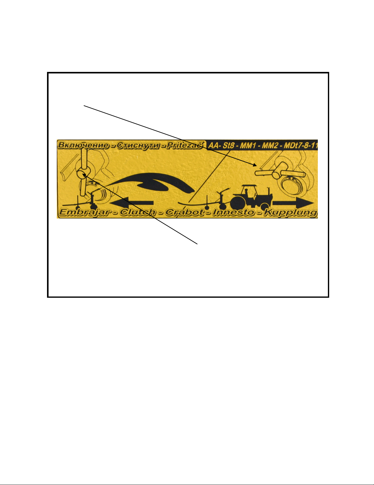
2. Never transport the Water-Reel with the an-return pawl disengaged! The tubing will become loose and
tangled. Do not aempt to operate your Water-Reel if there are any coils of tube that are loose or mis-
placed. If loose coils of tube are noced aer pulling the tube out, they must be ghtened by rotang the
spool with the hand crank. If this is not possible, pull all of the tube out before aempng to rewind the
tube.
3. Never try to move or relocate the machine if the tube is not fully rewound onto the machine.
4. Never pull the tube o the machine other than by pulling on the sprinkler cart (straight out from the ma-
chine).
5. Never run over the tube with any kind of vehicle and avoid pinching or pulling the tube around objects.
Never bend the tube sharper than 25 mes the inner diameter of the tube.
6. If the tube is frequently pulled out only a poron of its complete length the tube remaining on the drum
will become loose. Occasionally it will be necessary to pull all the tube o the drum to ghten the remain-
ing coils.
7. Be careful when operang other equipment near the tube. Make sure the tube doesn’t get gouged or
punctured.
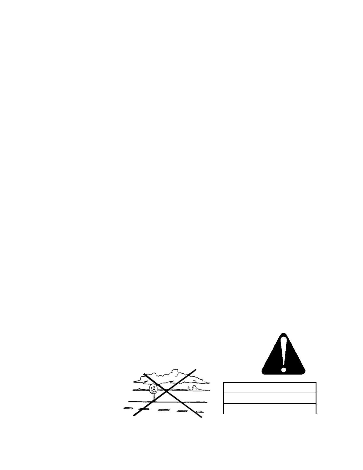
8. Never leave tube pulled out on ground for more than 12 hours prior to your irrigaon run.
9. Avoid using the PTO or engine drive to rewind the tube when it is not pressurized. When the tube is not
pressurized during rewind the tube will aen and the rewind mechanism cannot funcon properly. Keep
the tube pressurized when rewinding!
10. The Water-Reel’s gearbox is equipped with a brake to prevent coils of tube from becoming loose on the
tube spool due to freewheeling of the drum. Loose coils of tube will make the level-wind mechanism ap-
pear to be out of me. In this case, the level-wind system will be damaged and a mis-wrap will occur.
7

T23_AA_Operator Manual_2014 Revised 08/2014
Polyethylene Tube
Precauons for Handling
If your machine is exhibing signs of miswrapping, or loose tube see the Maintenance Secon, Page 28.
Note: If the tube is pulled out in an arc to follow a contour or to avoid an obstacle, the arc should be very
gradual. The arc should not begin unl at least 20% of the tube is rst pulled out straight from the machine.
Under no circumstances should the tube curve more than 90 degrees in its enre length. How well the tube
will follow its laid out path back to the machine will depend mostly on the surface of the ground. For exam-
ple, if there are contours or furrows to follow, the tube may track back very well. If the soil or vegetaon is
slippery and no rows or furrows exist, the tube may slide sideways across the laid out path and the sprinkler
cart will be recoiled back to the machine in a straight line instead of following the intended arc. This will place
an excessive side load on the level wind mechanism and may result in equipment failure or tube damage.
Assembly
Water-Reels are usually shipped with the primary assembly complete. The only items to assemble at the des-
naon are as follows:
1. Wheels. Make sure all lug bolts and axle adjustment bolts are ght. They must be rechecked aer being
towed for any distance greater than one mile.
2. Sprinkler Cart. Aach the sprinkler cart to the tube end.
3. Sprinkler. Install on the sprinkler cart riser pipe.
4. Sprinkler Nozzle. Install the appropriate sprinkler nozzle.
Final adjustment of the sprinkler cart li assembly should be made upon compleon of the rst irrigaon run.
The li hooks should be located directly above the sprinkler cart when the sprinkler cart is completely drawn
up to the compensaon/shut-o bar.
8

T23_AA_Operator Manual_2014 Revised 08/2014
Lubricaon
Water Resistant Grease (Figures 1-3, 5 & 6)
To keep your Water-Reel operang eciently, it is important to lubricate it at the designated locaons aer no
more than 100 operang hours or a minimum once per season. Water resistant grease should be ulized.
Oil (Figure 4)
The gearbox must be kept full of SAE 90 oil. There is an oil sight gauge to assist with assessing this.
Drum Support
Jack
Drum Support
Turntable Bearing
Stabilizer Leg
Hoseguide Mechanism
Fork Support
Figure 1
Bevel Gear Pair
Primary Chain
Secondary Chain
Figure 2
Figure 3
Figure 5
Figure 4
Figure Summary
1. Drum Support & Jack
2. Drum Support
3. Stabilizer Leg
4. Turntable Bearing
5. - Primary Chain
- Secondary Chain
- Right Angle Gearbox
(Bevel Gear Pair)
- Fork Support
9

T23_AA_Operator Manual_2014 Revised 08/2014
Start Up & Operaon
Start-Up & Operaon Procedure
Successful operaon of the Water-Reel irrigaon system depends a great deal on the operator’s understand-
ing of the proper pullout and start-up procedure. Do not aempt to operate this Water-Reel unl you read
and understand the preceding secon tled “Precauons when Handling the Polyethylene Tube”!
Step-by Step Operaon
1. Pull the Water-Reel to the area to be irrigated, parking your Water-Reel and tractor perpendicular to the
irrigaon lane. Pull the turntable lock pin and rotate the spool so that the sprinkler cart is facing down
your irrigaon lane and is approximately 90 degrees away from the chassis. Insert turntable lock pin the
turntable slot plate and replace the coer pin to secure it. Be especially careful to have the spool square-
ly aligned with the sprinkler cart travel path (Diagram Below).
Warning! Do not pull the tube o of the back of the machine. The sprinkler
cart and tube should always be pulled out at approximately a 90 degree angle
to the chassis (diagram below). The stabilizer legs will not hold the load of in-
coming tube if the chassis wheels are not approximately 90 degrees from the
sprinkler cart travel path. See diagram below.
Pull Into Posion Remove Lock Pin Rotate Turntable Replace Lock Pin
10

T23_AA_Operator Manual_2014 Revised 08/2014
Start Up & Operaon
Step-by Step Operaon Connued
2. Lower the stabilizer legs. Remove the coer pin to the slide bolt holding the stabilizer leg in posion while
holding the handle. Lower each leg into the ground and rmly stomp them into the ground. Replace the
slide bolt & coer pin once lowered.
Warning! Never operate the Water-Reel with only one stabilizer
leg in the ground or without the stabilizer feet rmly inserted in the
ground.
3. AA models are equipped with a standard hand crank jack for making height
adjustments. Lower the jack and level your unit, unhook and pull tractor around
into posion to pull sprinkler cart down the irrigaon lane.
1. Verify that the chassis of your Ag-Rain Water-Reel is level, if not adjust the jack
accordingly. Also verify that both stabilizer legs are securely in the ground.
2. Adjust sprinkler cart to the desired width. See “Specicaon” secon.
3. Lower the sprinkler cart from its transport posion. Set the desired sprinkler arc and conrm that the sprin-
kler is equipped with the proper nozzle. Note: Turbine drive irrigators have a minimum G.P.M. ow
requirement. Do not aempt to operate at ows or pressures dierent from those
listed on the “Performance Guide” decal that is installed on the machine.
4. Li An-Return pawl (Diagram below). Flip the pawl into the up posion.
Important! If the pawl is under pressure, remove the safety guard and the yellow sleeve on the gearbox PTO
sha and remove the key that locks the sha into posion.
An-Return Pawl
Remove Safety Shield Remove Yellow Sleeve Close up of Locking Key in
Sha
Remove Locking Key
11

T23_AA_Operator Manual_2014 Revised 08/2014
Start Up & Operaon
Step-by Step Operaon Connued
Rotate the hand wheel counter-clockwise. This will take pressure o the pawl so that it can be lied. Once
pressure is relieved, ip the pawl up into place. Important! Be careful not to turn the sha too far. Over-
rotang may cause the coils of tube to become loose or tangled. Rotate only enough to relieve pressure o
the pawl so it can be lied. Make certain to replace the key into the sha once complete and then replace
the yellow sleeve & safety guard.
10. Disengage the Gearbox via the Clutch Pin before pulling the tube out. Pull the clutch pin out and turn to set
in the groove (See clutch pin posions below).
Warning! Never pullout the guncart with the clutch pin engaged. This will severely damage the
gearbox.
11. Pull the sprinkler cart out the desired distance using your tractor; ulizing the chain, clevis and pin provided.
Use a gear in your tractor that will not exceed 3 MPH at full throle. Pull the tube out at a steady rate and
do not exceed 3 MPH. Do not start and stop during pull out as this contributes to spool coasng and may
result in loosening of the tube. Slow the tractor to 1 MPH or less for y feet prior to stopping. If this is the
rst run, pull out the full length of the tube. It is important that the rst run be a full length run so the
tube becomes packed ghtly on the reel and Timing can be veried. Refer to page 28.
Cauon! If the tube is pulled out in an arc, the rst 20% of the tube must be pulled
straight away from the machine. Failure to observe this limitaon places excessive side
load on the level wind mechanism and may result in equipment failure or tube damage.
See the secon tled “Handling The Polyethylene Tube”.
Engaged Position
Disengaged Position
12

T23_AA_Operator Manual_2014 Revised 08/2014
Start Up & Operaon
Step-by Step Operaon Connued
10. Verify that the coils of tube remaining on the drum are both coiled and packed
ghtly (photo). If they are not use the hand crank and PTO input on the gearbox to
ghten them.
11. Aach supply hose. Verify there are no kinks or twists in the supply hose.
12. Lower the an reverse pawl prior to engaging the drive system.
13. Verify the turbine is o and turn on your pump. If your supply lines have not been used for an extended
period of me, ush them prior to aaching to the Water-Reel.
14. Engage the gear box via the clutch pin.
15. Aer all air is purged from the system and the sprinkler is operang smoothly allow water to go through
the system for several minutes to carry out any trash or debris that may have been in the mainline pipe.
Aer the system is thoroughly ushed, start the drive system by engaging the turbine.
Turbine Drive
Engage turbine and adjust speed control knob
aer system is purged.
Warning! Do not pick up or hold
supply hose as it is being pressurized!
Engaged PositionDisengaged Position
Start
Stop
13

T23_AA_Operator Manual_2014 Revised 08/2014
Start Up & Operaon
Step-by Step Operaon Connued
16. Conrm the sprinkler is operang as expected and in the desired arc. The arc of the sprinkler will aect
the precipitaon applicaon of the system. Note the “Precip Rate” column on the performance guide lo-
cated on the Water-Reel. The lowest precipitaon rate will occur when the sprinkler is operang a full
360-degree circle.
Warning! Exercise the compensaon/shut-o bar to conrm that the engine and/
or gearbox, stop retracon when the sprinkler cart
reaches the machine. This conrms that the turbine
gate is properly adjusted and working. Always exercise
the compensaon/shut-o bar each me before the unit is restarted
to conrm proper operaon (See Page 26 for Adjustment). Do not
allow the machine to operate if the shut-o system is not working
properly. Damage will result if the machine fails to stop when the
irrigaon tube is completely rewound.
17. Observe pressure, travel speed, and sprinkler operaon. See the “Specicaon” secon of this manual for
performance informaon and then adjust speed to the desired travel rate.
18. When the sprinkler cart completes the irrigaon run and has contacted the compensaon/shut-o bar,
the retracon of the tube will stop. With the irrigaon run completed, stop the pump, li the sprinkler
cart into transport posion, retract the stabilizer legs, disconnect the supply hose, and rotate the spool
and cradle to the transport posion. The Water-Reel is now ready to be moved and set up in a new loca-
on. Alternately, the Water-Reel can be rotated 180° to irrigate in the opposite direcon while ulizing
the same water supply.
Sprinkler
Arc Limits
Note: The upper elbow at main bearing may
leak inially at low pressure, but will stop as
pressure increases.
Note: Arc sengs where the sprinkler never
throws water forward of the sprinkler cart could
make the sprinkler cart track o line. This is
caused by the connuous thrust of the sprinkler
that tries to push the tube towards the Water-
Reel. It is necessary to have some sprinkler
thrust which puts the Tube under tension.
Cauon! Do not engage or disengage the clutch pin under high loads. Engaging or disengaging under
high loads may damage the gear train.
14

T23_AA_Operator Manual_2014 Revised 08/2014
Start Up & Operaon
Depth of Water
The depth of water applied by the Water-Reel is regulated by the speed of the sprinkler moving across the
ground and the rate of water being discharged by the sprinkler head. The sprinkler nozzle size and the water
pressure at the sprinkler determine the rate of water discharged. The selecon of the sprinkler nozzle is made
based on the water supply and pump performance.
Aer the desired depth of water has been determined and the proper nozzle has been installed, follow the
steps in the following example to set the speed: (Assume: 1.46” ring nozzle in sprinkler, 120 psi inlet pressure
on pressure gauge, and a desired depth of water of 1 inch.
1. Find the proper secon in the performance Guide for the 1.46” ring nozzle.
2. Locate the 122-psi inlet pressure.
3. Find depth of applicaon 1.00 inch.
4. Set your travel speed as indicated (111 feet per hour in this example).
5. The water pressure on the sprinkler nozzle is 70 psi. The ow in gallons per minute being dis-
charged through the sprinkler is 355 and the weed diameter is 385 feet.
6. The eecve irrigated width is 270 feet and the maximum eecve irrigated length is 1455 feet.
7. You can also note the precipitaon rate (the rate that water is being applied to the soil) is 0.40
inches per hour. This computaon is based on a 320-degree arc of the sprinkler with the arc
symmetrical to the direcon of travel. See sprinkler arc seng in this secon.
8. Hours required for a complete run of about 13.2 can be read from the chart at the boom of the
performance guide entled “Retracon Speed of Irrigaon Tube (Ft/Hr)”.
Note: This informaon is based on standard lengths of tube for the various models. Any tube of a non-
standard length or diameter will substanally change the performance. Consult the factory for performance
informaon on non-standard tubes.
1
5
4
3
2
6
7
8
Sample
15

T23_AA_Operator Manual_2014 Revised 08/2014
Start Up & Operaon
Speed Compensaon
Speed compensaon is necessary for uniform applicaon of water. The buildup of tube on the spool gives the
spool a larger eecve circumference with each layer. With a constant speed of rotaon, each layer of tube
on the spool makes a signicant increase in the rate of sprinkler cart retracon speed during the irrigaon run.
From the beginning of the irrigaon run to the end of the run the typical speed increase of a hard-hose travel-
er is about 40%. This means that without speed compensaon, if you set the travel speed to apply 1 inch of
water at the beginning of the run, you will get only 0.6 inches at the end of the run. On the average, the depth
is only 0.8 inches. This level of uniformity is unacceptable in most cases.
To beer manage the uniformity of applicaon, the Water-Reels are equipped with a speed compensator.
The compensator slows the rotaon of the spool at approximately the same rate that the tube builds up on
the spool so the velocity of the incoming tube stays relavely constant throughout the irrigaon cycle.
The compensaon system monitors the diameter of the spool by use of a bar that rides on the tube and slows
the drive system to oset the increase in the circumference of the spool. The bar is aached mechanically to
the turbine motor or to the throle of an engine drive system.
For Cruise Control equipped machines, the Cruise Control electronically compensates the rotaon of the
spool. The Cruise Control knows the size of the Water-Reel it is controlling and knows how much tube is on
the spool. It then calculates the diameter of the spool and adjusts the rotaonal speed accordingly. The bar
that rides on the tube is not used for speed compensaon. It is used for shut-o in the event of a mis-wrap or
when the sprinkler cart reaches the machine.
The compensator systems will maintain a reasonably constant sprinkler cart retracon speed throughout the
run.
See the “Maintenance & Adjustments” secon in this manual for more informaon about adjusng the tur-
bine compensators.
16

T23_AA_Operator Manual_2014 Revised 08/2014
Start Up & Operaon
Travel Speed Indicator
The travel speed indicator (Taky) displays the ground speed of the sprinkler cart, amount of hose pulled o
machine and layers of tube on spool. The speed is shown in feet per hour for more informaon refer to taky
manual. Cruise Control equipped models do not have a tachometer. The speed is read directly from the
Cruise Control screen.
17
Table of contents
Other KIFCO Farm Equipment manuals
Popular Farm Equipment manuals by other brands

Art's-Way Manufacturing
Art's-Way Manufacturing 6812D Operator's manual

GREAT PLAINS
GREAT PLAINS RC2515 Operator's manual

Checchi & Magli
Checchi & Magli 998963 Use and maintenance manual

Anderson
Anderson 680HS quick start guide

Ferrari
Ferrari FPA MULTIPLA Operating and service manual

TURFCO
TURFCO Aerator PRO-26 Operator's manual