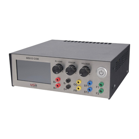
MSG MS021 User manual

MS021
UNIQUENESS
QUALIT Y SERVICE
WARRANTY TRAINING
INNOVATION
2020.03.20
USER MANUAL
TESTER FOR DIODES & RECTIFIERS
INSTRUKCJA OBSŁUGI
STANOWISKO DIAGNOSTYCZNE DO
TESTOWANIA GENERATORÓW SAMOCHODOWYCH
РУКОВОДСТВО ПО ЭКСПЛУАТАЦИИ
ТЕСТЕР ДЛЯ ПРОВЕРКИ ДИОДНЫХ
МОСТОВ


1
User Manual - MS021 Tester
English
INTRODUCTION...........................................................................................................................................................2
1. PURPOSE ................................................................................................................................................................. 2
2. TECHNICAL CHARACTERISTICS...........................................................................................................................3
3. EQUIPMENT PACKAGE...........................................................................................................................................4
4. DESCRIPTION OF THE DEVICE.............................................................................................................................4
5.
OPERATION
............................................................................................................................................................... 5
5.1 Safety regulations..........................................................................................................................................6
5.2 Rectier testing..............................................................................................................................................6
5.3 Tester setup ....................................................................................................................................................8
6. TESTER MAINTENANCE.........................................................................................................................................8
6.1 Cleaning and Care..........................................................................................................................................9
7. MAJOR FAULTS AND TROUBLESHOOTING....................................................................................................... 9
8. EQUIPMENT DISPOSAL ......................................................................................................................................10
CONTENTS

Thank you for purchasing the MSG Equipment product.
Tester for diodes and rectiers is manufactured from quality components and materials.
This manual contains information about the purpose, conguration, design, operation, technical
characteristics and operating rules of MSG MS021 tester.
The manufacturer reserves the right to change the design and software without prior notice to
users.
Read carefully this manual before putting MS021 (hereinafter referred to as the “Device”) into
operation, get special training at the equipment manufacturing facility if necessary.
MS021 has been engineered to satisfy the demand of big service stations and alternator repair
shops for the device which would allow quick and accurate rectier health checks. Testing
rectierswiththe useof multimeter has always beenthe most common practice.This method has a
signicant drawback -it doesn't help to identify the diode type and nd the faulty one. The test
current of a standard multimeter is about 0.002A, which is too low compared to the diode
operating currents.The test currentof MS021 is 0.9A which allows accurate diagnosingofa diode.
2
MS021 is designed to test the performance and structural integrity of automotive alternator
rectiers as well as of diodes separately.
The device detects:
-type of a diode (standard or avalanche);
-degradation of a diode (excessive forward voltage drop);
-avalanche diode reverse-breakdown voltage;
-diode breakdown;
-diode open-circuit failure;
-poor contact between the diode and the conductive busbars.
INTRODUCTION
1. PURPOSE
User Manual - MS021 Tester
English

3
2. TECHNICAL CHARACTERISTICS
3. CONTROL DEVICES
Dimensions (L*W*H), mm 219×214×80
Weight, kg 2
Supply voltage, V 230
Supply frequency, Hz 50
Supply type Single-phase
Consuming power, W No more than 40
Current load of diode test, A 0,9
The voltage on the open contact probes of the
device, V 30
Operating temperature, C˚ From +10 to +40
Storage temperature, C˚ From 0 to +50
User Manual - MS021 Tester
English

The MS021 package includes:
-MSG MS021 tester – 1 pc.;
-power cable – 1 pc.;
-diode fuse – (type: 5*20mm, current: 0.5A) – 1pc.;
-cable with a probe – 1 pc.,
-cable with a clamp – 1 pc.,
-User Manual – 1 pc.
Inspect MS021 tester. If any damage is detected, please contact the manufacturer or sales
representative before launching the equipment.
4
3. EQUIPMENT PACKAGE
4. TESTER DESCRIPTION
WARNING! In case of obvious damage, the operation of the device is forbidden.
The device is supplied with a touch screen (“1” - Fig.1) which displays the tested parameters; the
color indication of the screen signals the technical condition of the tested diode. The tester has
two connection terminals (“2” - Fig.1) for diagnostic cables (Fig.2). Any connection conguration
of cables is allowable. The encoder knob (“3” – Fig.1) is used for ne adjustment of the device for
specic tasks. Button “4” turns the device on. Diode fuse and power connectors are located at the
rear of the device.
Fig.1 MS021 tester. General view:
1 – Touch screen; 2 – Connection terminals for diagnostic cables;
3 – Encoder button; 4 – “ON” button.
123 4
User Manual - MS021 Tester
English

5
Fig.2. Diagnostic cables
Fig.3. MS021 tester. Back view:
1 – Diode fuse; 2 – Power connector.
2
1
5. OPERATION OF THE DEVICE
1.Use the device as intended.
2.The tester is intended for indoor use. When used outdoors, external conditions and technical
characteristics of the device set out in item 2 of this manual, should be taken into consideration.
3.To avoid failure or damage to the tester, do not make any changes to the electrical diagram of
the device on your own. In case of failure, please contact the manufacturer or sales
representative.
4.Do not leave the device with closed probes for more than 2 minutes.
5.Working with a measuring probe, keep your ngers on the plastic part of it. Touching the metal
part of the measuring probe may cause measurement errors.
User Manual - MS021 Tester
English

6
6.The device is equipped with a system for diagnostics of the probes condition. If any fault is
detected, the "PROBE PROBLEM" message will appear on the screen. The "DIODE BREAKDOWN"
message that appears when the probes are open, signals the probe failure. Check the
connection of the probes and ifthe problem persists, contact the customer service.
1.0nly the personnel that has received special training in safety operation and been authorized
to work with the test benches (devices) of certain types is allowed to use the device.
2.Make sure that measuring clamps do not have insulation damage or bare metal spots. Check the
clamps for any breaks. In case of obvious damage, replace them with the new ones before
launching the device.
Diagnostics of a rectier should be performed as follows:
1.Turn the tester on. Connect the clamp to the rectier housing. The following message will appear
on the screen: “CONNECT PROBE TO DIODE”.
2.Touch the contact spot of the tested diode with a probe. The following information will be
displayed:
“Vf” – diode voltage drop (in volts);
"Vr" - stabilizing voltage (in volts). If there are stabilitrons (avalanche diodes) in the rectier
structure, the "AVALANCHE" message will appear.
WARNING! Different contaminants and dirt on the tested contacts may lead to measurement
errors.
5.1. Safety regulations
5.2. Rectier testing
Б
Fig.4. Taking measurements.
А) – incorrect; Б) – correct
А
User Manual - MS021 Tester
English

7
2.1. If the diode is faultless, the screen will display “Vf” and “Vr”
values. The screen color will be green.
2.2. If the "Vf” value is higher than normal, the screen color will be
yellow.
2.3. If the diode is faulty, the screen color will be red.
The operability of the rectier should be decided on the basis of the “Vf” readings and type
(model) of the diode (stabilitron). The “Vf” absolute value is not always a key parameter when
checking the rectier. It is important to pay attention to the spread between the “Vf” values of
different diodes of the same rectier. For example, for a rectier that can carry 50 A, “Vf” = 0.850
V is quite typical. The rectier can be considered faultless If the spread between “Vf” values of
the diodes doesn’t exceed ± 0.020 V. For the 120A rectier, "Vf" = 0.850V is already a critical value.
The diode with such a "Vf" value shall be considered faulty.
2.4. In case of a short or open circuit failure, the screen color will be red and either the “SHORT
CIRCUIT’ or ‘DIODE BREAKDOWN’ message will be displayed correspondingly.
User Manual - MS021 Tester
English

8
The device assesses the diode performance on the basis of the forward voltage drop value (“Vf”)
and is specially calibrated to make it usable for any operator who doesn’t have sufcient
knowledge of the diode parameters and characteristics. Threshold values can be changed at the
user’s option.
Enter the “Settings” menu as follows:
1)Turn the device off.
2)Press and hold down the encoder button (“3” – Fig.1)
3)Turn the device on. A setup mode will be activated.
4)Threshold values for either a faultless diode (green color of the screen) or a faulty one (red
color of the screen) can be changed in this mode.
5)The selected threshold value can be changed by turning the encoder button clockwise or
counterclockwise.
6)To save the selected settings, press and hold down the encoder button until the device enters
the operating mode and the “CONNECT PROBE TO DIODE” message appears on the screen.
7)Turn the tester off to exit the setup menu. The settings won’t be saved.
5.3. Tester setup
Fig.5. Color threshold setting menu.
The test bench is designed for a long-continued full-time operation. However, to ensure uptime
of the test bench, it is necessary to provide regular technical inspection of the device and below
described routine maintenance as recommended:
The following main points should be checked in the course of a daily inspection:
•Whether the environment is permissible for the tester operation (temperature, humidity, air
pollution, vibration, etc.).
6. TESTER MAINTENANCE
User Manual - MS021 Tester
English

9
Soft tissues or wipe cloths should be used to clean the surface of the device neutral detergents.
The display should be cleaned with a special ber cloth and a screen cleaning spray. To prevent
corrosion, failure or damage to the tester, no abrasives or solvents should be used.
7. MAJOR FAULTS AND THEIR TROUBLESHOOTING
6.1. Cleaning and Care
•Whether the wires for connection to the tester terminals are in good condition (visual
inspection).
•Whether the measuring probes are in healthy condition (visual inspection).
•Do not store or use the device in premises where there is a high temperature, humidity,
danger of explosion or re, strong magnetic eld. As a result of exposure to dampness, the
tester performance may deteriorate.
User Manual - MS021 Tester
English
Problem Possible cause Troubleshooting
recommendations
1. Tester doesn’t turn on.
1.1. The power connector came
off.
1.2. The fuse burnt out.
1.1. Check the connection
reliability.
1.2. Replace the fuse.
2. “PROBE PROBLEM” message
appears when the tester is on. 2. Check the diagnostic probes
for damage. 2. Replace the diagnostic
probes.
3. “DIODE BREAKDOWN”
message appears when the
probes are open.
3. Check the reliability of the
connection of the probes.
3.1. Recover the contact.
3.2. Replace the diagnostic
probes.
4. The tested parameters are
displayed incorrectly.
4.1. Check the diagnostic
probes for damage.
4.2. Software error.
4.1. Recover the contact.
4.2. Clean the contact.
4.3. Contact the sales
representatives.

10
Признак неисправности Возможные причины Рекомендации по
устранении
5. The information is displayed
only partially.
5.1. Check the diagnostic
probes for damage.
5.2. Software error.
5.1. Replace the diagnostic
probes.
5.2. Contact the sales
representative.
European WEEE Directive 2002/96/EC (Waste Electrical and Electronic Equipment Directive)
applies to MS021 disposal.
Obsolete electronic equipment and electric appliances including cables and hardware as well as
batteries and accumulators must be disposed of separately from the household rubbish.
Use available waste collection systems to dispose of outdated equipment.
Proper disposal of old appliances prevents harm to the environment and personal health.
8. EQUIPMENT DISPOSAL
User Manual - MS021 Tester
English

11
Instrukcja obsługi - tester MS021
Polish
WPROWADZENIE .......................................................................................................................................................12
1. PRZEZNACZENIE ....................................................................................................................................................12
2. PARAMETRY TECHNICZNE...................................................................................................................................13
3. KOMPLETOWANIE.................................................................................................................................................14
4. ОPIS URZĄDZENIA.................................................................................................................................................14
5. CEL ZASTOSOWANIA.............................................................................................................................................15
5.1 Zasady bezpieczeństwa...............................................................................................................................16
5.2 Sprawdzanie mostka diodowego.............................................................................................................16
5.3 Konguracja urządzenia ............................................................................................................................18
6. OBSŁUGA URZĄDZENIA ......................................................................................................................................18
6.1 Czyszczenie i obsługa.................................................................................................................................. 19
7. GŁÓWNE NIESPRAWNOŚĆI I SPOSOBY ICH USUWANIA.............................................................................19
8. UTYLIZACJA ...........................................................................................................................................................20
SPIS TREŚCI

12
Instrukcja obsługi - tester MS021
Polish
Dziękujemy za wybranie produktów MSG Equipment.
Urządzenie do diagnostyki mostków diodowych MSG MS021 wykonane jest z wysokiej jakości
komponentów i materiałów.
Niniejsza instrukcja obsługi zawiera informacje o celu, wyposażeniu, konstrukcji, zasadzie
działania, parametrach technicznych i zasadach eksploatacji urządzenia MS021.
Producent zastrzega sobie prawo do zmiany konstrukcji i oprogramowania bez uprzedniego
powiadomienia użytkowników..
Przed użyciem MS021 (dalej urządzenie) należy uważnie przeczytać niniejszą instrukcję obsługi, w
razie potrzeby przejść specjalne szkolenie u producenta urządzenia.
Celem opracowania urządzenia MS021 jest potrzeba dużych stacji serwisowych i pracowni
naprawy generatorów w urządzeniu, co pozwala szybko i dokładnie określić stan techniczny
mostka diodowego. Najczęstszym sposobem oceny stanu technicznego mostka diodowego jest
sprawdzenie diod za pomocą multimetru. Ta metoda ma znaczną wadę - niemożność określenia
rodzaju diody i zidentykowania diody, w której wydajność uległa pogorszeniu. Konwencjonalny
multimetr sprawdza prąd o wartości około 0,002A. Ta wartość prądu jest zbyt mała w porównaniu
z prądami roboczymi diody. Urządzenie MS021 sprawdza diodę prądem o wartości 0,9A, co
pozwala dokładnie ocenić stan diody.
Urządzenie MS021 zostało zaprojektowane do oceny wydajności i integralności mostków
diodowych generatorów samochodowych, a także osobno diod.
Urządzenie pozwala ustalić:
-rodzaj diody (zwykła dioda, dioda lawinowa);
-degradacja diody (zwiększony spadek napięcia w kierunku do przodu);
-napięcie odwrotnego przebicia diody lawinowej;
-awaria diody;
-obryw diody;
-obecność słabego kontaktu diody z oponami przewodzącymi.
WPROWADZENIE
1. PRZEZNACZENIE

13
Instrukcja obsługi - tester MS021
Polish
2. PARAMETRY TECHNICZNE
Wymiary (D*S*W), mm 219×214×80
Waga, kg 2
Napięcie zasilania, V 230
Częstotliwość sieci, Hz 50
Rodzaj sieci Jednofazowa
Zużycie energii nie więcej, W. 40
Siła prądu podczas sprawdzania diody, A 0,9
Napięcie prądu przemiennego na otwartych
sondach, V 30
Temperatura robocza, °C od +10 do +40
Temperatura przechowywania, °C od 0 do +50

14
Instrukcja obsługi - tester MS021
Polish
Zestaw urządzeń diagnostycznych MS021 zawiera:
- Urządzenie MSG MS021-1 szt.;
- kabel zasilający-1 szt.;
- bezpiecznik topikowy (typ 5x20мм, ток 0,5А)-1 szt.;
- kabel z sondą-1 szt.;
- kabel z zaciskiem-1 szt.;
- instrukcja obsługi-1 szt.
Sprawdź urządzenie MS021. W przypadku stwierdzenia uszkodzenia przed włączeniem urządzenia
należy skontaktować się z producentem lub przedstawicielem handlowym.
3. KOMPLETOWANIE
4. ОPIS URZĄDZENIA
OSTRZEŻENIE! W przypadku widocznych uszkodzeń korzystanie z urządzenia jest
zabronione.
Urządzenie zawiera ekran 1 rys. 1, który wyświetla zmierzone parametry i wskazuje stan
technicznego testowanej diody za pomocą kolorowej indykacji. Dwa złącza 2 rys. 1 do podłączania
kabli diagnostycznych (patrz rys. 2). Kable diagnostyczne można podłączyć w dowolnej
kombinacji. Pokrętło enkodera 3 rys. 1 służy do precyzyjnego dostrojenia urządzenia do
określonych zadań. Przycisk 4 odpowiada za włączenie urządzenia. Z tyłu urządzenia (patrz rys. 3)
znajduje się bezpiecznik i złącze do podłączenia kabla zasilającego.
Rysunek 1. Ogólny widok urządzenia MS021:
1 - Ekran; 2 - Złącza do kabli diagnostycznych;
3 – Enkoder z przyciskiem; 4 - Przycisk zasilania.
123 4

15
Instrukcja obsługi - tester MS021
Polish
Rysunek 2. Kable diagnostyczne
Rysunek 3. Ogólny widok urządzenia MS021 widok z tyłu:
1 - Bezpiecznik; 2 - Złącze do kabli zasilających.
2
1
5. CEL ZASTOSOWANIA
1.Używaj urządzenia tylko zgodnie z jego przeznaczeniem.
2.Urządzenie jest przeznaczone do użytku w pomieszczeniach. Podczas korzystania z urządzenia
na ulicy należy wziąć pod uwagę warunki otoczenia i parametry techniczne urządzenia opisane w
p. 2.
3.Aby uniknąć uszkodzenia lub awarii urządzenia, nie wolno dokonywać zmian w obwodzie
elektrycznym urządzenia według własnego uznania. W przypadku awarii skontaktuj się z
producentem lub przedstawicielem handlowym.
4.Nie pozostawiaj urządzenie z zamkniętymi sondami na dłużej niż 2 minuty.
5.Podczas pracy z sondą trzymaj palce na plastikowej części. Dotknięcie metalowej części sondy
podczas pomiarów może spowodować błędy pomiaru.

16
Instrukcja obsługi - tester MS021
Polish
6.Urządzenie jest wyposażone w system diagnostyczny sondy. Jeśli urządzenie wykryje problem z
sondami, na ekranie pojawi się napis «PROBE PROBLEM/PROBLEM Z SONDĄ». Jeśli na ekranie
pojawia się «DIODE BREAKDOWN/AWARIA DIODY» przy otwartych sondach, oznacza to również
problem z sondami. Sprawdź, czy połączenie jest prawidłowe i niezawodne, czy sondy są
prawidłowo podłączone, jeśli problem będzie się powtarzał, skontaktuj się z pomocą techniczną.
1.Specjalnie przeszkolone osoby, które otrzymały prawo do pracy na niektórych typach stojaków
(urządzeń) i zostały przeszkolone w zakresie bezpiecznych metod i metod pracy, mogą pracować
z urządzeniem.
2.Upewnij się, że cęgi pomiarowe nie są uszkodzone w izolacji lub odsłoniętym metalu. Sprawdź
otwory w zaciskach. W przypadku stwierdzenia uszkodzenia należy wymienić urządzenie przed
użyciem.
Sprawdzanie mostka diodowego jest wykonane w następujący sposób:
1.Włącz urządzenie. Podłącz zacisk do obudowy mostka diodowego. Na ekranie zostanie
wyświetlony komunikat «CONNECT PROBE TO DIODE/PODŁĄCZ SONDA DO DIODY».
2.Za pomocą sonda dotknij styku testowanej diody. Na ekranie zostaną wyświetlone następujące
informacje:
«Vf» - spadek napięcia diody w woltach;
«Vr» - napięcie stabilizacyjne (w woltach) i komunikat «AVALANCHE/LAWINA» - jeśli diody Zenera
są używane w mostku diodowym (diody lawinowe).
OSTRZEŻENIE! Obecność różnych zanieczyszczeń na testowanych stykach może prowadzić
do niedokładnych pomiarów.
5.1. Zasady bezpieczeństwa
5.2. Sprawdzanie mostka diodowego
Б
Rysunek 4. Wykonywanie pomiarów:
A) - źle; Б) - dobrze
А

17
Instrukcja obsługi - tester MS021
Polish
2.1 Jeśli dioda działa, zostaną wyświetlone wartości «Vf» i «Vr». Ekran
będzie zielony.
2.2. Jeśli dioda ma podwyższoną wartość «Vf» - ekran będzie żółty.
2.3. Jeśli dioda jest uszkodzona, ekran zmieni kolor na czerwony.
Decyzję o kondycji mostka diodowego należy podjąć na podstawie odczytów «Vf» i rodzaju
(modelu) diody (diody Zenera). Wartość bezwzględna «Vf» nie zawsze jest decydującym
parametrem podczas sprawdzania mostka diodowego. Ważne jest, aby zwrócić uwagę na
rozpiętość «Vf» między różnymi diodami tego samego mostka diodowego. Na przykład dla mostka
diodowego o wartości 50 A wartość «Vf» = 0,850 V może być dość typowa. Jeżeli rozproszenie «Vf»
między diodami nie przekracza ± 0,020 V, taki mostek diodowy można uznać za sprawny. W
przypadku mostka diodowego 120 A wartość Vf = 0,850 V jest już niezwykle wysoką wartością.
Diodę z takim «Vf» należy uznać za wadliwą.
2.4. W przypadku zwarcia lub otwartej diody - ekran będzie miał kolor czerwony, a także
odpowiednie komunikaty «SHORT CIRCUIT/KRÓTKI OBWÓD», «DIODE BREAKDOWN/AWARIA
DIODY» odpowiednio.

18
Instrukcja obsługi - tester MS021
Polish
Urządzenie ocenia stan techniczny diody na podstawie wielkości spadku napięcia w kierunku do
przodu «Vf» i jest skongurowane tak, aby mógł być używany przez dowolnego operatora bez
wystarczającej wiedzy o parametrach i charakterystyce diod. Urządzenie pozwala na zmianę
wartości progowych według własnego uznania.
Aby wejść do menu ustawień (rys. 5), wykonaj następujące czynności:
1)Wyłącz urządzenie.
2)Zaciśnij przycisk enkodera (patrz poz. 3 rys. 1).
3)Włącz urządzenie. Urządzenie przejdzie w tryb konguracji.
4)W tym trybie można zmienić wartość progową, po której kolor ekranu zmienia się na czerwony,
a wartość progową, po której kolor ekranu zmienia się na żółty. Krótkie naciśnięcie przycisku
enkodera umożliwia przełączanie między edytowalną wartością progową.
5)Obróć enkoder w prawo lub w lewo, aby zmienić wybraną ramkę.
6)Aby zapisać wybrane ustawienia, należy nacisnąć i przytrzymać przycisk enkodera, aż urządzenie
przejdzie w tryb pracy i na ekranie pojawi się kommunikat «CONNECT PROBE TO DIODE/PODŁĄCZ
SONDA DO DIODY».
7)Aby wyjść z menu ustawień bez zapisywania zmian, należy wyłączyć urządzenie.
5.3. Konguracja urządzenia
Rysunek 5. Menu ustawienia progu indykacji kolorowej
Urządzenie MS021 jest przeznaczone do długotrwałej pracy przez całą dobę. Jednak w celu
uzyskania maksymalnego czasu sprawności konieczne jest regularne sprawdzanie i, jak opisano
poniżej, prolaktyka z zalecaną częstotliwością.
Poniżej znajdują się główne punkty, które należy sprawdzić podczas codziennej inspekcji:
•Czy środowisko jest akceptowalne dla działania stojaka (temperatura, wilgotność,
zanieczyszczenie powietrza, wibracje itp.).
6. OBSŁUGA URZĄDZENIA
Table of contents
Languages:
Other MSG Test Equipment manuals