manuals.online logo
Brands
  1. Home
  2. •
  3. Brands
  4. •
  5. Kilargo
  6. •
  7. Fire And Smoke Damper
  8. •
  9. Kilargo IFD44-LL Series User manual

Kilargo IFD44-LL Series User manual

Wall Mounted Systems
15 Wentworth Place, Banyo Qld 4014
T 1300 858 010 |F +61 7 3861 9266 |E [email protected] |www.kilargo.com.au
Step 1 Position damper centrally in penetration aperture as per system drawing with
IBS Backing Rod and temporary supports or packers.
Step 2 Apply Kilargo Intumescent Mastic (supplied separately) to the gaps between
the damper & building element. Ensure fill depth corresponds with those
detailed in the system drawing.
Step 3 Fasten mounting angles to damper with steel self-drilling screws or steel pop
rivets and, if detailed, to the building element with appropriate mechanical
fixings as per system drawing.
Step 4 Ensure product and certification labels are in a prominent position for easy
identification during subsequent maintenance inspections.
Step 5 Connect ductwork to the damper casing with AS 1682.2 compliant breaka-
way joint.
IFD44-LL Series: Hebel
Installation Instructions:
Ducted
System Notes
• Grilles, louvres, IBS backing rod & fixings are to be supplied by others.
• Kilargo Intumescent Fire Dampers shall be installed in accordance with this detail,
including the use of Kilargo Intumescent Mastic and in accordance with the
requirements of AS1682.2.
• Ensure convenient access is provided for visual inspection and cleaning as necessary.
• 2mm Minimum gap allowable between damper and aperture. For gaps between
2-5mm, a fillet of Kilargo Intumescent Mastic shall be applied.
FRL -/120/-
System No. WH11 (a)
Building element: Hebel
Application: Mounted in casing DD / DG
in 75SW system hebel wall
Maximum size: 300 x 300 *without build up
FRL -/120/-
Test reference No. FAS200229
*Max size 1200 x 1200 if wall thickness is built
up locally with 100mm wide FR plasterboard to
a minimum thickness of 116mm
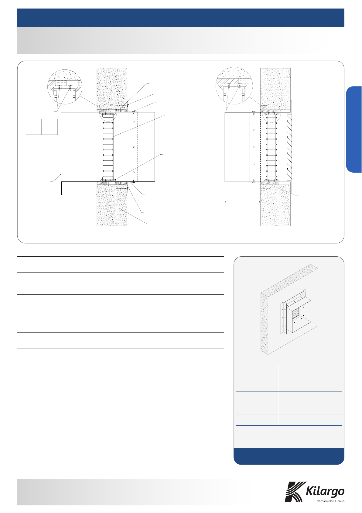
Duct to Duct Duct to Grille
Casing length 150mm MAX
from face of the wall
Gaps between damper casing and
wall system firestopped with Kilargo
Intumescent Mastic 50mm deep.
Max gap 25mm
Kilargo IFD44-LL fixed
into ductwork with steel
tek-screws or pop rivets
Casing length on either
side of wall 150mm MAX
0.7mm or greater
Z275 gal steel casing
positioned centrally
within aperture
IBS Backing Rod
Kilargo Intumescent
fire damper fixed to
steel casing
Kilargo Intumescent
Mastic applied to entire
perimeter of IFD44-LL
damper (on both sides)
Gaps between casing and
wall system firestopped
with Kilargo Intumescent
Mastic 25mm deep.
Max gap 25mm
Hebel 75SW Wall
Minimum 0.7mm steel angles at least
twice the width of the penetration gap,
fixed to damper casing with steel screws,
bolts or pop rivets and fixed to wall with
steel fixings at maximum 150mm centre
spacing or:
-2 per side for casing lengths up to 250mm
-3 per side for casing lengths 251-400mm
8G x 65mm Coarse Thread Screw
Steel Tek Screw
Kilargo IFD44-LL fixed into
ductwork with steel tek-screws
or pop rivets as follows:
Side Length Qty of Screws
0-100mm
101-250mm
251-400mm
401-600mm
1 set
2 sets
3 sets
4 sets
Wall Mounted Systems
15 Wentworth Place, Banyo Qld 4014
T 1300 858 010 |F +61 7 3861 9266 |E [email protected] |www.kilargo.com.au
Wall Mounted Systems
Step 1 Apply Kilargo Intumescent Mastic to the opposing module.
Step 2 Align and bring modules together and mechanically fix together using U
channels and steel self-drilling screws or steel pop rivets with 2 sets of
screws at 150mm centres as per the modular system drawing on both sides.
Step 3 Fix modular damper to aperture or casing as shown in the appropriate
system drawing and installation instructions.
System Notes
• Fixings are to be supplied by others.
• Optional flat joining strips supplied at the time of order in lieu of U channel on request
for air transfer systems only.
1.50
20
30
U Channel
U Channel
2mm Kilargo
Intumescent
Mastic
IFD44-LL modules fixed together
using steel self drilling screws at
max. 150mm centre spacings
with 2 sets of screws
Galvanised Steel
U Channel 30mm x
20mm x 1.5mm
Frames spot welded together
and mastic applied to joint
IFD44-LL Series: Hebel
Installation Instructions:
Ducted - Modular
FRL -/120/-
System No. WH11 (b)
Building element: Hebel
Application: Mounted in casing DD / DG
in 75SW system hebel wall
Maximum size: 300 x 300 *without build up
FRL -/120/-
Test reference No. FAS200229
*Max size 1200 x 1200 if wall thickness is built
up locally with 100mm wide FR plasterboard to
a minimum thickness of 116mm
Note: To be read in conjunction with system
WH11 (a)

Popular Fire And Smoke Damper manuals by other brands

NuAire NRG-ILTIM Installation and Maintenance

NuAire

NuAire NRG-ILTIM Installation and Maintenance

Mandik SEDS-L manual

Mandik

Mandik SEDS-L manual

Mandik FDMD installation instructions

Mandik

Mandik FDMD installation instructions

Mandik FDMB manual

Mandik

Mandik FDMB manual

Johnson Controls RF-2000 installation instructions

Johnson Controls

Johnson Controls RF-2000 installation instructions

SMAY KWP-L Technical documentation

SMAY

SMAY KWP-L Technical documentation

MAT Roto-Twist RT-150 Series Installation & operation instructions

MAT

MAT Roto-Twist RT-150 Series Installation & operation instructions

Greenheck ESK-402 Installation, operation and maintenance

Greenheck

Greenheck ESK-402 Installation, operation and maintenance

LUCOMA RGK-10 Series Installation, operation and maintenance instructions

LUCOMA

LUCOMA RGK-10 Series Installation, operation and maintenance instructions

System air FDR-3G Handbook

System air

System air FDR-3G Handbook

System air PKIR-E60S Installation, operation and maintenance instructions

System air

System air PKIR-E60S Installation, operation and maintenance instructions

eControls R80DV Installer manual

eControls

eControls R80DV Installer manual

Aprilaire 6108 installation instructions

Aprilaire

Aprilaire 6108 installation instructions

Honeywell Home TrueZONE Bypass installation instructions

Honeywell Home

Honeywell Home TrueZONE Bypass installation instructions

Alnor MANDIK FDMC manual

Alnor

Alnor MANDIK FDMC manual

Rf-t CU2 manual

Rf-t

Rf-t CU2 manual

Nailor 1290F quick start guide

Nailor

Nailor 1290F quick start guide

Lindab FNC1 Installation booklet

Lindab

Lindab FNC1 Installation booklet

manuals.online logo
manuals.online logoBrands
  • About & Mission
  • Contact us
  • Privacy Policy
  • Terms and Conditions

Copyright 2025 Manuals.Online. All Rights Reserved.