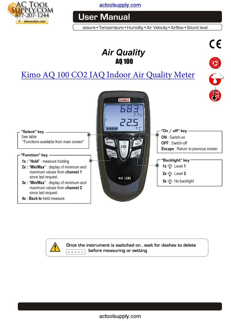
Kimo KIGAS 310 User manual


Table of contents
ANALYSER
1. Introduction.....................................................................................................................................................................................7
1.1. Description of the analyser........................................................................................................................................ 7
1.1.1. Overview of the gas analyser............................................................................................................................ 7
1.1.2. Presentation of the keypad and screen.............................................................................................................8
1.1.3. onnection of the analyser............................................................................................................................... 8
1.2. Main features............................................................................................................................................................ 9
1.3. Technical features................................................................................................................................................... 11
2. Safety............................................................................................................................................................................................12
2.1. Precautions for use................................................................................................................................................. 12
2.2. Symbols used......................................................................................................................................................... 12
2.3. Safety instructions................................................................................................................................................... 12
3. Perform a flue gas analysis..........................................................................................................................................................13
3.1. Prepare the instrument before the analysis............................................................................................................. 13
3.2. Perform an analysis................................................................................................................................................ 13
3.3. Zoom function......................................................................................................................................................... 14
3.4. Assign the analysis to a customer........................................................................................................................... 14
3.5. Add the measurement to a group............................................................................................................................ 14
3.6. Print the analysis results......................................................................................................................................... 14
4. Perform a quick measurement......................................................................................................................................................15
5. Set the different parameters of the analyser................................................................................................................................16
5.1. Instrument setting.................................................................................................................................................... 16
5.1.1. Screen setting................................................................................................................................................. 16
5.1.2. Set the auto-off................................................................................................................................................ 16
5.1.3. hange the language...................................................................................................................................... 16
5.1.4. Modify date and time....................................................................................................................................... 16
5.1.5. Ticket printing setting...................................................................................................................................... 17
5.1.6. Activate or deactivate the visual support......................................................................................................... 17
5.1.7. Activate the group function.............................................................................................................................. 17
5.1.8. Select the alarm sound................................................................................................................................... 18
5.1.9. Activate or deactivate Bluetooth® function (optional).......................................................................................18
5.2. Set the combustible................................................................................................................................................. 18
5.2.1. Modify a combustible...................................................................................................................................... 18
5.2.2. Add a combustible........................................................................................................................................... 19
5.2.3. Delete a combustible....................................................................................................................................... 19
5.3. Set the alarms, measurement units and O protection........................................................................................... 19
5.3.1. Set the alarms................................................................................................................................................. 19
5.3.2. Set the measurement units............................................................................................................................. 19
5.3.3. Set the O protection threshold...................................................................................................................... 19
5.3.4. Set the display................................................................................................................................................ 20
5.4. Set the references................................................................................................................................................... 20
5.5. Set the auto-zero and purge time............................................................................................................................ 20
5.6. Set the operators..................................................................................................................................................... 20
5.6.1. Add an operator.............................................................................................................................................. 20
5.6.2. Modify the operator name............................................................................................................................... 20
5.6.3. Delete an operator.......................................................................................................................................... 21
5.7. Back to factory setting of the analyser.................................................................................................................... 21
5.7.1. Units and values of measurement settings of the factory setting....................................................................21
5.7.2. Device factory setting...................................................................................................................................... 21
6. Manage customers.......................................................................................................................................................................22
6.1. reate a customer................................................................................................................................................... 22
6.2. Modify a customer................................................................................................................................................... 22
6.3. Delete a customer................................................................................................................................................... 22
7. Manage boilers..............................................................................................................................................................................23
7.1. reate a boiler........................................................................................................................................................ 23
7.2. Modify a boiler......................................................................................................................................................... 23
7.3. Delete a boiler......................................................................................................................................................... 23
8. Manage the inspections................................................................................................................................................................24
8.1. Get to inspections................................................................................................................................................... 24
8.2. reate an inspection............................................................................................................................................... 24
8.3. Delete an inspection................................................................................................................................................ 24
8.4. reate a group........................................................................................................................................................ 24
8.5. Add an inspection to a group................................................................................................................................... 25
8.6. Delete a group........................................................................................................................................................ 25
9. Perform measurement of a customised procedure......................................................................................................................25
9.1. Preliminary operations to procedures...................................................................................................................... 25

9.2. Launch a customised procedure............................................................................................................................. 25
10. Perform a control of gas flow......................................................................................................................................................26
10.1. Perform a measurement of theoretical flow........................................................................................................... 26
10.2. Perform a measurement of real flow..................................................................................................................... 26
10.3. Results interpretation............................................................................................................................................ 26
11. Perform a gas network leak test.................................................................................................................................................27
11.1. Perform the test..................................................................................................................................................... 27
11.2. Link the measurement to a customer.................................................................................................................... 27
11.3. Print the results..................................................................................................................................................... 27
12. Perform a pressure measurement..............................................................................................................................................28
12.1. Perform a draft measurement............................................................................................................................... 28
12.2. Perform a differential pressure measurement....................................................................................................... 28
12.3. Perform a flue gas velocity measurement............................................................................................................. 28
12.4. Link the measurement to a customer.................................................................................................................... 28
12.5. Add the measurement to a group.......................................................................................................................... 28
12.6. Print the results..................................................................................................................................................... 28
13. Perform a measurement of ambient O2...................................................................................................................................29
13.1. Perform the measurement.................................................................................................................................... 29
13.2. Link the measurement to a customer.................................................................................................................... 29
13.3. Add the measurement to a group.......................................................................................................................... 29
13.4. Print the results..................................................................................................................................................... 29
14. Perform a measurement of Max O...........................................................................................................................................30
14.1. Perform the measurement.................................................................................................................................... 30
14.2. Link the measurement to a customer.................................................................................................................... 30
14.3. Add the measurement to a group.......................................................................................................................... 30
14.4. Print the results..................................................................................................................................................... 30
15. Perform some temperature measurements................................................................................................................................31
15.1. Perform a measurement of ambient temperature..................................................................................................31
15.2. Perform a measurement of flue gas temperature.................................................................................................. 31
15.3. Perform an ambient temperature measurement with the internal sensor..............................................................31
15.4. Perform a Flow/Return temperature measurement...............................................................................................31
15.5. Link the measurement to a customer.................................................................................................................... 31
15.6. Add the measurement to a group.......................................................................................................................... 31
15.7. Print the results..................................................................................................................................................... 31
16. Perform a measurement of opacity............................................................................................................................................32
16.1. Perform the measurement.................................................................................................................................... 32
16.2. Enter the indexes in the analyser.......................................................................................................................... 32
16.3. Link the measurement to a customer.................................................................................................................... 32
16.4. Add the measurement to a group.......................................................................................................................... 32
16.5. Print the results..................................................................................................................................................... 32
17. Perform a measurement of ionisation current............................................................................................................................33
17.1. Perform the measurement.................................................................................................................................... 33
17.2. Link the measurement to a customer.................................................................................................................... 33
17.3. Add the measurement to a group.......................................................................................................................... 33
17.4. Print the results..................................................................................................................................................... 33
18. Perform a H4 measurement......................................................................................................................................................34
18.1. Perform the measurement with the probe............................................................................................................. 34
18.2. Perform the measurement with the sensor...........................................................................................................34
18.3. Link the measurement to a customer.................................................................................................................... 34
18.4. Add the measurement to a group.......................................................................................................................... 34
18.5. Print the results..................................................................................................................................................... 34
19. Perform a flue gas velocity measurement with a Pitot tube.......................................................................................................35
19.1. Link the measurement to a customer.................................................................................................................... 35
19.2. Add the measurement to a group.......................................................................................................................... 35
19.3. Print the results..................................................................................................................................................... 35
20. To get to information about the analyser....................................................................................................................................36
20.1. Information............................................................................................................................................................ 36
20.2. Diagnostics........................................................................................................................................................... 36
20.2.1. Air flow.......................................................................................................................................................... 36
20.2.2. Gas leak test................................................................................................................................................. 37
21. Maintenance of the analyser.......................................................................................................................................................38
21.1. Life-time of the sensors......................................................................................................................................... 38
21.2. Replace the paper roll of the printer...................................................................................................................... 40
21.3. Replace the battery............................................................................................................................................... 40
22. alculations of the different parameters.....................................................................................................................................41
22.1. O, NO and NOx conversions.............................................................................................................................. 41
22.2. alculation of the level in NOx.............................................................................................................................. 41
22.3. alculation of flue gas velocity.............................................................................................................................. 41

SOFTWARE
1. Introduction...................................................................................................................................................................................44
2. Software installation......................................................................................................................................................................44
2.1. Recommended minimum configuration................................................................................................................... 44
2.2. Installation............................................................................................................................................................... 44
3. Start with the software..................................................................................................................................................................45
3.1. Meaning and functions of the menus bar (1)...........................................................................................................45
3.2. Meaning and functions of tool bar buttons (2)......................................................................................................... 46
3.3. Meaning and functions of the homepage buttons (3).............................................................................................. 46
4. Download inspections...................................................................................................................................................................46
5. Use the different databases..........................................................................................................................................................47
5.1. Use the customer database.................................................................................................................................... 47
5.2. Use the boilers database........................................................................................................................................ 48
5.3. omplete database................................................................................................................................................. 50
5.3.1. Database settings........................................................................................................................................... 50
5.3.2. Save while using............................................................................................................................................. 50
5.3.3. Import a database........................................................................................................................................... 50
5.4. Edit an analysis report............................................................................................................................................. 51
6. Set the analyser............................................................................................................................................................................52
6.1. hange the combustibles........................................................................................................................................ 52
6.2. hange the references............................................................................................................................................ 52
6.3. Manage the operators............................................................................................................................................. 52
6.4. Modify the date and time......................................................................................................................................... 53
6.5. Sensors state.......................................................................................................................................................... 53
6.6. Set printings............................................................................................................................................................ 53
6.7. Battery level............................................................................................................................................................ 53
6.8. Access to information about the instrument and update the instrument..................................................................53
6.8.1. Access to information about the instrument....................................................................................................53
6.8.2. Update the device........................................................................................................................................... 53
The Internet connection is not protected by a proxy...........................................................................................53
The Internet connection is protected by a proxy................................................................................................. 54
6.8.3. Install a 3rd language....................................................................................................................................... 54
6.8.4. Send a report of the device to the After-Sales Service....................................................................................55
6.8.5. Back to factory parameters............................................................................................................................. 55
7. Options..........................................................................................................................................................................................55
7.1. E-mail...................................................................................................................................................................... 55
7.2. User information...................................................................................................................................................... 55
7.3. hange the language.............................................................................................................................................. 55
8. ustomers / Boilers deletion of the analyser................................................................................................................................56
9. ompare the instrument and software information......................................................................................................................57
9.1. Add elements automatically in the databases......................................................................................................... 57
9.2. Modification of customer and boilers features......................................................................................................... 57

6Introduction

1. Introduction
1.1. Description of the analyser
The KIGAZ 310 is a flue gas analyser with two interchangeable sensors (long-life O2 and CO-H2), with an additional possibility of 2 sensors, or an
analyser with three interchangeable sensors (long-life O2, CO-H2 and NO) with an additional possibility of a 4th sensor NO2,SO2 or CH4), or an
analyser with 4 sensors (long-life O2, CO-H2, NO and NO2 or SO2).
Its main features are the following :
•Self-test of the instrument
•CO-H2 dilution
•Integrated water trap with maximum level alarm
•Colour TFT screen
•Integrated printer
•2 thermocouple connections
•2 Go of memory
The gas analyser is supplied in a transport case in ABS or metallic optional) with a magnetic protective cover, a differential pressure kit, an
interchangeable flue gas probe of 300 mm length with integrated draft and LED, a Li-Ion battery and its charger, the LIGAZ-2 software, a USB cable
and a calibration certificate. A paper roll for the printer and a filter are also provided.
This gas analyser is designed to control arameters of flue gas in exhaust duct of heating units. It can not be used in a
ermanently way and/or used as an alarm system.
1.1.1. Overvie of the gas analyser
Introduction 7
Over-moulded handle
Flue gas probe
Integrated water trap
Integrated printer
TFT 3.5'' colour screen
Single connector for
flue gas probe
TcK+gas) and draft
Water trap discharge
LED
Fixing cone
Filter location
LED button

1.1.2. Presentation of the keypad and screen
1.1.3. Connection of the analyser
8Introduction
T1 and T2 thermocouple
connections
C1 connection for external probe
Pt100 temperature, CH4,...)
Flue gas probe connection
P- pressure tap
P+ pressure tap
USB
connection
To view Bottom view Right side view
Function keys
On/Off button
OK button
Esc button
Home screen
Customers menu
Setting menu
Measurement menu
Procedures menu
Information menu
Light for battery
charging
Power supply
Gas outlet
Directional arrows

1.2. Main features
•Screen
Back-lighted TFT 3.5'' colour screen. It allows to display measured parameters in a more comfortable format for the operator. Thanks to the zoom
function with directional arrows), you can view on the screen the measured values in increased characters.
•Printer
The paper of the instrument is a thermal paper with a 10-year guarantee. Printer has an easy replacement system of the paper Easyload). In
addition, printing is fast.
•Battery charger
The instrument is supplied with a 6 V, 1.5 A power adapter to load the internal batteries. The current loading is indicated by a battery symbol on the
top left of the screen. The red LED on the right side of the gas analyser stays on until the battery loading is completed. The battery charging time is
10 hours. The voltage of the power supply is 100-240 VAC, 50/60 Hz. The number of cycles of the battery is about 500 charging cycles.
•Flue gas suction um
The pump, inside the gas analyser, is a diaphragm pump with a motor. It is energized in direct current directly by the instrument in a way to get an
optimal suction of flues gases. The pump is regulated by a continuous measurement of the output flow by the pressure sensor n°3.
•Flue gas robe
Probe in stainless steel with an over-moulded handle in plastic, with a standard length of 30 cm and with a fixing cone to maintain the contact tip in
the duct. Interchangeable, it has a LED allowing to light the dark areas. The probe is connected to the instrument by a neoprene tube of 2.50 m.
The handle is also equipped with a filter that keeps the solid particles of flue gases during the combustion analysis.
•Interchangeable measurement sensors
The analyser uses electrochemical sensors to measure the oxygen and the carbon monoxide compensated in H2 hydrogen). Measurement sensors
are interchangeable. Recharge regularly the battery to guarantee an optimal operating of the electrochemical sensors.
•Tem erature sensors
Flue gas temperature is measured with a thermocouple integrated in the contact tip. The connection to the analyser is made thanks to a single male
connector compensated in temperature. K thermocouple nickel-nickel chromium) allows continuous measurements up to 1250 °C.
The instrument has a NTC thermoresistance for the measurement of internal temperature; this sensor is also used for the measurement of ambient
temperature.
If a temperature control of the combustive air must be performed directly by the supply duct room sealed boiler), a Pt100 temperature probe ref :
SPA 150 SP) will be used. It is recommended to perform this measurement to make the efficiency calculation of the installation more accurately.
•Pressure sensors
The analyser has 3 piezoelectric internal sensors for the measurement:
1 – of the differential pressure Delta P) with manual auto-zero
2 – of the high accuracy draft with auto-zero by solenoid valve
3 – of the pump output flow with a regulation which allows to compensate a clogging of the filter or a high draft. This sensor allows to perform the
tightness test of the analyser.
•Su ly in ut of flue gases and +/- ressure
The analyser has a single connector allowing the connection of flue gas probe.
•Combustibles ty es
The analyser is supplied with a memorisation of technical data which characterises the 15 most known combustibles. It is also possible to add 5
combustibles and their corresponding features.
•Calibration certificate
The analyser is calibrated by comparison with standard of metrology laboratories, which are periodically certified closed to laboratories known at the
international level. Each analyser is supplied with its calibration certificate in which, for every parameters, are indicated the nominal value, the one
measured, the admitted error limits and the found error.
•Conformity and standards
The analyser complies with n°2004/108/EC directive on electromagnetic compatibility. Document available on request. It also complies with
2006/95/EC Low Voltage, 2011/65/EU RoHS II and 2012/19/WEE directives.
Moreover, the analyser complies with EN 50379-1 and 50379-2 standards. except NO2 and SO2 sensors).
•Water tra
The water trap is integrated to the KIGAZ 310. Measured gases go through the probe filter then through the water trap which recovers the liquid
element and, as a result, protects the sensors.
Condensates are evacuated by the opening of the plug located on the bottom on the instrument.
When the maximum level is reached, a red LED lights and the pump stops. It allows to warn the user when the water trap must be emptied.
Introduction 9

The resence of a water tra with a filter can, in some cases, cause the solubility of some gases in water during a flue gas
analysis.
•Customers management
The analyser allows to record customers, theirs respective boilers and inspections. Once the features of customers and boilers are completed in the
analyser, the operator can easily assign the different measured values to a customer and his boiler. These data can then printed and/or transferred
to a computer thanks to LIGAZ-2 software.
•Auto-zero
The analyser has the “auto-zero in the duct” function, it means that the operator can perform measurements draft, temperature...) while the analyser
inhales fresh air in the room. This function allows to save time on the inspection locations.
•CO dilution
The instrument has the CO dilution function that allows to avoid high CO concentrations. These high concentrations can damage the analyser and
its sensors. This function allows to increase the CO concentration without damage the sensor. In dilution function, the range becomes 0-5% 50 000
ppm). The dilution can also be activated during a flue gas analysis by pressing the OK key of the instrument.
•O acity index measurement (o tional)
It is possible to fill in the analyser with opacity index values measured according to the Bacharach scale. The analyser will calculate the average and
results will be printed on the ticket. This measurement must be performed with an opacity pump which is available as an accessory ref: PMO).
•Gas network leak testing (o tional)
It is possible to check the tightness of an installation. For this control, use the pressure sensor used for the differential pressure measurement ref:
KEG).
•Gas flow
It is possible to measure the gas flow of an installation, to compare it with a theoretical gas flow and as a result to estimate the installation
consumption.
•Measured values
- O2: percentage of oxygen in flue gases
- CO: concentration of CO in flue gases
- NO: concentration of NO in flue gases
- NO2: concentration of NO2 in flue gases
- SO2: concentration of SO2 in flue gases
- Tf: flue gases temperature
- Ta: combustive air temperature
•Calculated values
- λ: Air Excess : connection between the volume of combustive air and the requested volume necessary for a combustion in
stoichiometric conditions.
- CO2: percentage of carbon dioxide in flue gases.
- ΔT: difference between the flue gases temperature and the combustive air temperature.
- NOx: concentration of NOx in flue gases calculated with the NO sensor, or measured with the NO and NO2 sensors)
- Qs: percentage of waste heat throughout the chimney.
- ηs: Lower efficiency (or sensible): calculated burner efficiency. This is a ratio between the conventional heating power and the burner
heating power. Among the combustion losses, only the sensible heat lost with the flue gases is taken into account, neglecting the radiation
losses and incomplete combustion losses. This value is referred to LHV Lower Heating Value) and can not be higher than 100%.
The sensible efficiency value is to be compared with the minimum efficiency stated for the heating systems performances.
- ηt: Higher efficiency (or total): is the sum of sensible efficiency and the additional efficiency deriving from the recovery of water vapour
condensation contained in the flue gases. When it s greater than sensible efficiency, then condensation is taking place. It is referred to
LHV Lower Heating Value) and can exceed 100%. The LHV is calculated by an algorithm developed by Kimo and its value must be
considered as indicative.
- CO (O2): Concentration of CO in flue gases in mg/m3. It is calculated according to O2 reference value indicated in the analyser
see page 20).
- NO (O2): Concentration of NO in flue gases in mg/m3. It is calculated according to O2 reference value indicated in the analyser
see page 20).
- NOx (O2): Concentration of NOx in flue gases in mg/m3. It is calculated according to O2 reference value indicated in the analyser
see page 20)
10 Introduction

1.3. Technical features
Parameters Sensor Measuring range Resolution Accuracy* T90 res onse time
Long-life O2Electrochemical From 0 % to 21 % 0.1 % vol. ±0.2 % vol. 30 s
CO
(with H2
com ensation)
Electrochemical From 0 to 8000 ppm 1 ppm
From 0 to 200 ppm: ±10 ppm
From 201 to 2000 ppm:
±5 % of the measured value
From 2001 to 8000 ppm:
±10 % of the measured value
30 s
NO Electrochemical From 0 to 5000 ppm 1 ppm
From 0 to 100 ppm: ±5 ppm.
From 101 to 5000 ppm:
±5 % of the measured value
30 s
Low range NO Electrochemical From 0 to 500 ppm 0.1 ppm
From 0 to 40 ppm: ±2 ppm
From 41 to 500 ppm:
±5 % of the measured value
30 s
NOx Calculated** From 0 to 5155 ppm 0.1 ppm or
1 ppm*** - -
NO2Electrochemical From 0 to 1000 ppm 1 ppm
From 0 to 100 ppm: ±5 ppm.
From 101 to 1000 ppm:
±5 % of the measured value
80 s
SO2Electrochemical From 0 to 5000 ppm 1 ppm
From 0 to 100 ppm: ±5 ppm.
From 101 to 5000 ppm:
±5 % of the measured value
80 s
CO2Calculated** From 0 to 99 % vol 0.1% vol - -
CH4Semiconductor
From 0 to 10000 ppm
From 0 to 1 % vol
From 0 to 20 %LEL
1 ppm
0.0001 % vol
0.002 %LEL
±20 % of full scale 40 s
Flue gas
tem erature K thermocouple From -100 to +1250 °C 0.1 °C ±0.4 % of the measured value or ±1.1 °C 45 s
Ambient
tem erature Internal NTC From -20 to +120 °C 0.1 °C ±0.5 °C
Ambient
tem erature
Pt100 1/3 DIN
external probe) From -50 to +250 °C 0.1 °C ±0.3 % of the measured value ±0.25 °C 30 s
Dew oint
tem erature Calculated** From 0 to +99 °Ctd 0.1 °C - -
DHW tem erature TcK external
probe) From -200 to +1300 °C 0.1 °C ±0.4 % of the measured value or ±1.1 °C -
Draft Piezoelectric
From -10 to +10 Pa
From -1000 to
+1000 Pa
0.1 Pa
1 Pa
From -100 to -10 Pa: ±2 Pa
From -10 to +10 Pa: ±0.5 Pa
From +10 to +100 Pa: ±2 Pa
Above: ±2 % of the measured value
-
Differential ressure Piezoelectric From -20 000
to +20 000 Pa 1 Pa
From -20 000 to -751 Pa:
±0.5 % of the measured value ±4.5 Pa
From 750 to -61 Pa:
±0.9 % of the measured value ±1.5 Pa
From -60 to 60 Pa: ±2 Pa
From 61 to 750 Pa:
±0.9 % of the measured value ±1.5 Pa
From 751 to 20 000 Pa:
±0.5 % of the measured value ±4.5 Pa
-
Losses Calculated** From to 100% 0.1% - -
Flue gas velocity Calculated** From to 99.9 m/s 0.1 m/s - -
Excess air (λ) Calculated** From 1 to 9.99 0.01 - -
Lower efficiency (ηs) Calculated** From 0 to 100% 0.1 % - -
Higher efficiency (ηt)
(condensation) Calculated** From 0 to 120% 0.1% - -
O acity index External instrument From 0 to 9 - - -
* All accuracies indicated in this document were stated in laboratory conditions and can be guaranteed for measurements carried out in the same conditions, or carried out with required
compensation.
** Calculation is made based on the measured values by the analyser.
***The resolution is 0.1 ppm if the O sensor is a low range O sensor (0-500 ppm). The resolution is 1 ppm if the sensor is a O 0-5000 ppm.
Introduction 11

2. Safety
2.1. Precautions for use
Please always use the device in accordance with its intended use and within parameters described in the technical features in order not to
compromise the protection ensured by the device.
2.2. Symbols used
For your safety and in order to avoid any damage of the device, please follow the procedure described in this user
manual and read carefully the notes preceded by the following symbol:
The following symbol will also be used in this user manual:
Please read carefully the information notes indicated after this symbol.
2.3. Safety instructions
The following safety instructions have to be strictly observed.
Not res ecting these safety instructions can lead to a loss of warranty.
•The analyser should not to be used in and under water.
•The analyser should not to be laced near or directly at o en fire or heat.
•The indicated range of tem erature of the robe is not to be exceeded, as the robe and tem erature sensor could be destroyed.
•After measurements, before acking the analyser, wait for the robe to be cold. As long as it is hot, the robe could cause
injuries.
•The exhalations of alcohol liquids (lubricants, etrol, s irit, vanish...) may damage the sensors of the analyser. Therefore, it is
forbidden to reserve or use these fluids nearby the analyser.
•Load the battery only with Kimo charger. The charger must be used only for the ower su ly loading. Use another ty e of
charger can damage the battery and the analyser and can cause electrical shocks.
12 Safety

3. Perform a flue gas analysis
3.1. Prepare the instrument before the analysis
During the measurement, the analyser must be in vertical osition or in horizontal osition. Do not hold the analyser in inclined
osition.
Before the 1st use of the analyser, a full charge of the battery must be made during 12 hours.
Em ty the water tra .
In case of any default or damage of the instrument, Kimo After-sales service shall be contacted. On the back of the analyser,
there is a label with the analyser serial number. This number shall be communicated for every o eration (technical o eration or
request of s are arts).
3.2. Perform an analysis
➢Connect the flue gas probe to the analyser.
➢Turn on the instrument.
Home screen is displayed.
➢Insert the probe in the flue as shown on the figure for at least 3 minutes.
➢Press OK.
The screen with the different possible measurements is displayed.
Remaining time of auto-zero and its progress bar are displayed at the bottom of the screen.
Measurements covered by the auto-zero are not available (Combustion, Max CO and ambient CO2).
At the end of the auto-zero, these menus are available.
Take advantage of the auto-zero to perform the draft.
➢Go to “Flue gas” with the up and down arrows.
➢Press OK.
The screen displays the different combustibles in the analyser.
➢Select the type of used combustible by the boiler with the up and down arrows.
➢Press OK.
The screen displays values of the different parameters of the analysis.
Perform measurement for at least 3 minutes.
Perform a flue gas analysis 13
To hold the measurement, press
the function button.

3.3. Zoom function
From the gas analysis screen, the zoom function is available using the direction arrows.
The initial screen displays 12 measured values.
➢To zoom in, press the right arrow.
The screen displays 6 measured values.
➢To zoom in again, press the right arrow.
The screen displays 3 measured values.
➢To zoom in again, press the right arrow.
The screen displays one measured value.
➢To zoom out, press the left arrow.
➢At any time, press the down arrow to scroll the values.
3.4. Assign the analysis to a customer
At the end of the analysis, when measurements are constant, it is possible to assign it to a customer recorded in the analyser or to unrecorded
customer that should be created.
➢Press the function button.
The analyser displays the list of recorded customers.
➢Select a customer with up and down arrows then press OK or create a customer see page 22) then select it.
The analyser displays the list of available boilers.
➢Select the boiler with up and down arrows then press OK or create a boiler see page 23) then select it.
The analyser backs to the measurement screen of the analysis.
3.5. Add the measurement to a group
The groups allow to regroup measurements in folders. The group function has to be activated see page 17).
Once the measurement is linked to a customer and a boiler, it is possible to add it in a group in the instrument, or create a group:
The analyser proposes to add the measurement to a group.
➢Go to YES and press OK.
➢Go to the required group with the arrows and press OK, or create a group see page 24).
The analyser backs to the measurement screen.
3.6. Print the analysis results
It is possible to print the results on the ticket:
➢Press the function button.
Results are printed on the ticket.
See page 17 for the printing configuration.
14 Perform a flue gas analysis

4. Perform a quick measurement
The quick measurement allows to perform in a few seconds:
•a flue gas measurement
•a draft measurement
•and an ambient CO measurement with Max CO.
➢During the quick measurement, it is possible to print a ticket at each step by pressing the function button, or print the whole
measurements when the analyser proposes it at the end of the quick measurement screen 13).
Perform a quick measurement 15
* If the CO SCOT robe is used, select “External” then follow the instructions on the analyser.

5. Set the different parameters of the analyser
The “Setting” menu allows to set the following parameters:
•Instrument screen, printing, auto-off,...)
•Combustibles
•Measurement
•References O2, atmospheric pressure and altitude)
•AutoZ/Purge
•Operators
The “Setting” art allows to set arameters that can affect the erformed measurements. These settings must be made by a
qualified technician only.
5.1. Instrument setting
5.1.1. Screen setting
This part allows to set the backlight of the screen from 1 to 9.
➢Turn on the instrument.
Home screen is displayed.
➢Go to “Setting” with the up and down arrows then press OK.
➢Go to “Instrument” then press OK.
➢Press OK on the “Screen” line.
➢Go to the parameter to set then press OK.
➢Use the up and down arrows to increase or decrease the value.
➢Press OK to validate.
5.1.2. Set the auto-off
The auto-off allows to turn off the analyser automatically after some time of non-use.
It is possible to set the auto-off at 15 / 30 / 45 / 60 / 90 or 105 minutes or to deactivate it.
“Setting > instrument” screen is displayed.
➢Go to “Auto-off” with the up and down arrows then press OK.
➢Select the required time of auto-off or “Off” to deactivate it with the up and down arrows.
➢Press OK to validate.
5.1.3. Change the language
It is possible to select the language of the instrument: French or English in standard. A third language is downloadable through the LIGAZ-2
software.
“Setting > Instrument” screen is displayed.
➢Go to “Language” with the keypad then press OK.
➢Select the language with the keypad.
➢Press OK.
5.1.4. Modify date and time
“Setting > Instrument” screen is displayed.
➢Go to “Date/time” with the keypad then press OK.
➢Go to the parameter to modify with the keypad day, month, year, hour, minute or second).
➢Press OK.
➢Use the up and down arrows to modify the selected parameter.
➢Press OK.
➢Repeat the procedure on another parameter if required.
➢Go to “Date Format” with the keypad then press OK.
➢Select “Day/Month” to display the day then the month or “Month/Day” to display the month then the day then press OK.
➢Go to “Time Format” with the keypad then press OK.
➢Select the time format: “12” or “24”.
If 12 is selected, “AM” for ante meridiem or « PM » for post meridiem will be displayed in front of the time.
➢Press the function key to quit the screen and save the modifications or press Esc to cancel.
16 Set the different parameters of the analyser

5.1.5. Ticket printing setting
“Setting > Instrument” screen is displayed.
➢Go to “Printing” with the keypad then press OK.
➢Go to “Format” with the keypad then press OK.
➢Select the ticket format: long or short with the keypad then press OK.
ong ticket format: prints the headers, the user name, the
selected customer and boiler, the type of device and its serial
number, the type of combustible, the inspection date and time
and the measurements results.
Short ticket format: prints only the device reference, the
type of combustible, the date and time and the
measurement results.
➢Go to “Logo” then press OK to activate it: ON or deactivate it: OFF.
➢Go to the first line of the “Header” then press OK.
The keyboard appears at the bottom of the screen.
➢Select the letters with the keypad then press OK.
➢Press the function key to validate the line.
The keyboard disappears.
➢Press Esc to back to “Setting instrument” screen and validate modifications.
•To go from lower-case keyboard to upper-case keyboard then to numeric keyboard: press the function key.
•To erase a letter: press the function key.
5.1.6. Activate or deactivate the visual support
The visual support corresponds to help windows displayed met during a measurement procedure. It allows to communicate with application.
“Setting > Instrument” screen is displayed.
➢Go to “Su ort” with the keypad.
➢Go to “Visual su ort” line with the keypad.
➢Press OK to activate it: ON or to deactivate it: OFF.
5.1.7. Activate the group function
Groups allow to gather measurements in a folder. To activate it:
“Setting > Instrument” screen is displayed.
Set the different parameters of the analyser 17

➢Go to “Grou ” with the keypad.
➢Press OK to activate it: ON or to deactivate it: OFF.
For the groups creation and management, see page 24.
5.1.8. Select the alarm sound
“Setting > Instrument” screen is displayed.
➢Go to “Audio” with the keypad then press OK.
➢Press again OK
➢Select with the keypad the Alarm 1 sound or the Alarm 2 sound then press OK.
5.1.9. Activate or deactivate Bluetooth® function (optional)
Bluetooth® allows to communicate with the Kigaz mobile application.
“Setting > Instrument” screen is displayed.
➢Go to “Bluetooth” with the keypad.
➢Press OK to activate it: ON or to deactivate it: OFF.
The icon appears on the instrument screen when it is activated.
When Bluetooth® is activated, Kigaz appears with the name “Kigaz” in the available devices list of the computer, tablet or smartphone.
5.2. Set the combustible
15 different combustibles are recorded in the analyser:
Sahara / Fos Natural gas Cannel-coal
Groninguen – Natural gas Low volatile coal
Russia – Natural gas Coke gas
Propane Biofuel 5%
LPG Wood 20%
Butane Hog fuel 21%
Light oil Pellet 8%
Heavy fuel oil
See page 21 for the measurements parameters units and values list of a factory setting.
5.2.1. Modify a combustible
Each combustible has its own coefficient allowing to calculate flue gases CO2, excess losses and efficiencies in the most accurate way.
The modification of these coefficients will lead some modifications in combustion analysis results. Only a qualified technician
is authorized to modify them.
It is still ossible to reset the factory arameters ressing the “Factory arameters” function key or with the LIGAZ-2
software (see age 55).
It is possible to modify the name of a combustible and its type of energy solid, liquid or gas):
“Setting > Combustibles” screen is displayed.
➢Go to the required combustible with the up and down arrows then press OK.
➢Press “OK” on “Name” line.
The keyboard appears.
➢Select the letters with the direction arrows and press OK to validate.
•To go from lower-case keyboard to upper-case keyboard then to numeric keyboard: press the function key.
•To erase a letter: press the function key.
➢Press the function key to validate the new combustible name.
➢Press “OK” on the “Energy” line.
➢Select the combustible energy type: solid, liquid or gas and press OK.
➢Press the function key.
The instrument backs to the combustible list with the modifications applied.
It is also possible to modify the combustible coefficients:
“Setting > Combustibles” screen is displayed.
➢Go to the required combustible with the up and down arrows then press OK.
➢Go to the “Coefficient” line and press OK.
➢Go to the coefficient to modify with the up and down arrows then press the function key.
The coefficient modification field is displayed.
➢Modify the values with the arrows and press OK to validate.
➢Press Esc to go back to the previous screen.
➢Press the function key to save the new combustible.
18 Set the different parameters of the analyser

5.2.2. Add a combustible
Up to 5 combustibles can be added in the instrument's memory:
“Setting > Combustibles” screen is displayed.
➢Press the function key.
“Add combustible” screen is displayed.
➢Press OK.
The keyboard appears.
➢Enter the name of the combustible with the keypad and press OK.
➢Press the function key to validate the name of the new combustible.
➢Go to “Energy” line with the keypad and press OK.
➢Select “Solid”, “Liquid” or “Gas” with the keypad and press OK.
➢Press the “Save” function key to save the new combustible.
Screen backs to the list of combustible. The new combustible in well on the list in last position.
Every coefficient of the new combustible is set at 0.
➢Follow the procedure of modification of combustible coefficients described page 18.
5.2.3. Delete a combustible
“Setting > Combustibles” screen is displayed.
➢Go to the combustible to delete with the keypad.
➢Press the function key.
5.3. Set the alarms, measurement units and CO protection
5.3.1. Set the alarms
It is possible to activate an alarm for each measurement parameter. This alarm can be rising the alarm of the instrument is activated when the
measured value exceeds the defined threshold) or falling the alarm of the instrument is activated when the measured value is below the defined
threshold).
It is possible to set an alarm for the following parameters:
O2, CO, Amb. CO, CH4, CO2, Qs losses), λ excess air), ηt lower efficiency), ηs higher efficiency), Tf flue gas temperature),
Ta ambient temperature), Td dew-point temperature), Pr. pressure), ΔP differential pressure), draft.
“Setting” menu is displayed.
➢Go to “Measurement” with the keypad then press OK.
➢Press OK on “Alarms” line.
➢Go to the parameter to modify with the keypad then press the function key.
The edge (rising or falling) and the threshold of the selected parameter are displayed.
➢Go to the “Edge” line with the keypad then press OK.
Select the type of alarm with the keypad:
•Rising edge:
•Falling edge:
•Deactivated alarm:
➢Press OK.
➢Go to the “Threshold” line then press OK
The keyboard appears.
➢Modify the alarm threshold value with the arrows and press OK to validate.
➢Validate the threshold with the function key.
➢Press Esc to quit the screen.
5.3.2. Set the measurement units
It is also possible to select the measurement unit for each measured parameter:
•Tem erature: °C, °F
•Pressure: Pa, inWg, hPa, mbar, mmHg, mmH2O, PSI
•CO / COrefO2 / CO2 / NO / NOrefO2 / NO2 / NOx / NOxrefO2 / SO2: ppm, mg/m3, mg/kWh, g/kWh, g/GJ, g/m3, %
•CH4: ppm, %vol, %LIE
“Setting” menu is displayed.
➢Go to “Measurement” with the keypad then press OK.
➢Go to “Units” with the keypad then press OK
➢Go to the parameter to modify with the keypad then press OK.
The list of the available units according to the parameter appears.
➢Go to the requested unit with the keypad then press OK.
➢Press Esc to quit the screen.
5.3.3. Set the CO protection threshold
The CO protection allows to protect the instrument against high concentrations of CO. If the protection threshold is exceeded, the instrument will
start the CO dilution. To set this threshold:
“Setting” menu is displayed.
Set the different parameters of the analyser 19

➢Go to “Measurement” with the keypad then press OK.
➢Go to “CO rotection” with the keypad then press OK.
➢Go to “CO threshold” and press OK.
The modification field of the threshold value is displayed.
➢Modify the threshold with the arrows.
➢Press OK to validate the new threshold.
5.3.4. Set the display
“Setting” menu is displayed.
➢Got to “Measurement” with the keypad then press OK.
➢Go to “Dis lay” with the keypad then press OK.
➢Press the function key to activate or deactivate the measurement display.
➢Press the function key to validate.
5.4. Set the references
The “Setting > References” screen allows to set the features of the measurement environment: O2 reference, %NO2 for the Nox calculation),
altitude and atmospheric pressure. These data are used to calculate the efficiency.
These setting must be erformed by a qualified technician.
“Setting” menu is displayed.
➢Go to “References” with the keypad then press OK.
➢Select the parameter to modify with the keypad then press OK.
The modification field of the reference is displayed.
➢Enter the parameter value with the keypad then press OK to validate.
5.5. Set the auto-zero and purge time
The auto-zero allows the analyser to exhaust ambient fresh air and as a result to put the sensors at 0 ppm. It is possible to configure the auto-zero
time and to activate the automatic auto-zero, i.e. an automatic activation of the auto-zero with a defined interval.
“Setting” screen is displayed.
➢Go to “AutoZ/Purge” line with the keypad then press OK.
➢Press OK.
The list of available duration appears: 30, 40 or 50 seconds, 1, 2, 3, 4 or 5 minutes.
➢Go to the required duration then press OK.
➢To activate the automatic auto-zero, go to « Automatic auto-zero » line then press OK.
The “Interval time” line appears.
➢With the down arrow go to “Interval time” line then press OK.
The interval time list is displayed: 5, 10, 15, 20, 25 or 30 minutes.
➢Select the required interval then press OK.
➢Press Esc to quit the screen.
5.6. Set the operators
It is possible to enter in the analyser names of operators who will use the instrument. The operator who performs an analysis appears on the ticket
only for the long size format).
5.6.1. Add an operator
“Setting” screen is displayed.
➢Go to “O erator” with the keypad then press OK.
➢Press the function key.
The keyboard appears.
➢Enter the name with the keypad: press OK to validate.
➢Press the function key to validate the operator name and to add it in the list.
The analyser backs to the list of present operators.
➢Press Esc to quit the screen.
5.6.2. Modify the operator name
“Setting” screen is displayed.
➢Go to “O erator” with the keypad then press OK.
➢Press the function key.
The keyboard appears.
➢Modify the name with the keypad: press OK to validate.
➢Press the function key to validate the operator name.
The analyser backs to the list of current operators.
➢Press Esc to quit the screen.
20 Set the different parameters of the analyser
Table of contents
Other Kimo Measuring Instrument manuals