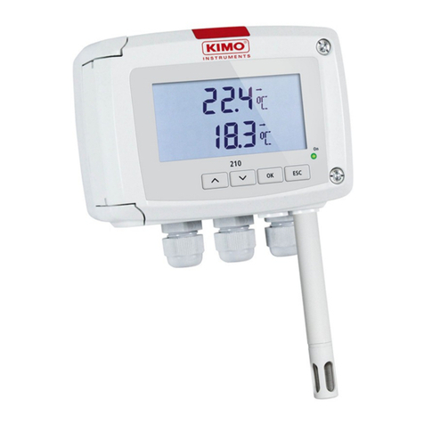
1. Prerequired ........................................................................................P 1
1.a - Working principle ........................................................................P 1
1.b - Output signal selection . . . . . . . . . . . . . . . . . . . . . . . . . . . . . . . . . . . . . . . . . . . . . . . . . . . . . . . . . . . . . . . . . . P 1
1.c - Protection tip of the sensor .............................................................P 1
2. Code activation and access to functions...............................................P 2
3. Display and keypad configuration • F100 ..............................................P 3
3.a - Backlight .................................................................................P 3
3.b - Display contrast control .................................................................P 3
3.c - Keypad locking...........................................................................P 4
4. Configuring channels and units of measurement • F200 . . . . . . . . . . . . . . . . . . . . . . . . P 5
5. Analogue output management • F300 ...................................................P 6
5.a - Output diagnostics.......................................................................P 7
5.b - Analogue output settings................................................................P 8
6. Relay / Alarm settings • F400..............................................................P 10
6.a - Activation / Deactivation of BEEP alarm..............................................P 10
6.b - Relay security ..........................................................................P 10
6.c - Alarm/relay functions and LED colour codes .........................................P 11
6.d - Channel selection for alarms/ relays..................................................P 12
6.e - Alarm mode details.....................................................................P 13
6.f - Alarm mode selection ..................................................................P 15
6.g - Setpoints and time-delay setting ......................................................P 16
7. Pressure measurement configuration • F500 .......................................P 18
7.a - Pressure measurement integration (CP 200) ........................................P 18
7.b - Autozero . . . . . . . . . . . . . . . . . . . . . . . . . . . . . . . . . . . . . . . . . . . . . . . . . . . . . . . . P 18
8. Humidity measurement configuration • F500 .......................................P 19
8.a - Offset settings in Humidity and temperature (TH 200) ..............................P 19
9. Air velocity measurement configuration • F600 ...................................P 20
9.a - Temperature compensation (CP 200) ................................................P 20
9.b - Air velocity coefficient selection (CP 200) ............................................P 21
9.c - Air velocity correction coefficient input (CP and CTV 210) ..........................P 22
Table of contents
Class 200 transmitter configuration via keypad
