Kindermann 7488000 User manual

HDMI-HDBaseT Receiver Plus PoC
Art.-Nr. 7488000063
Ref. No. 7488000063
GB
D
Bedienungsanleitung
Operating instructions

2
Bestimmungsgemäße Verwendung - Designated use
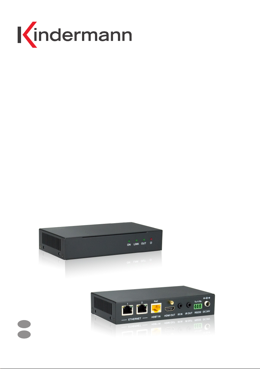
Mit dem HDMI-HDBaseT Receiver Plus PoC werden HDMI-, Ethernet- und Kontroll-Signale (IR & RS232)
bis 1080p und 100 MBit mittels Twisted Pair Kabel bis zu einer Entfernung von 90 m übertragen.
Benötigt werden Transmitter und Receiver.
HDMI-HDBaseT Receiver Plus PoC for the transmission of HDMI, Ethernet and control signals (IR & RS232)
via twisted pair cable over a distance of up to 90 m at 1080p and 100 MBit. Requires transmitter and
receiver.
Lieferumfang - Contents
Sicherheitshinweise - Safety instructions
• Bitte die Anleitung sorgfältig durchlesen und aufbewahren
• Umsetzer dürfen nur mit Sicherheitskleinspannung betrieben werden
• Das System darf nur in trockener Umgebung bei Raumtemperatur gelagert und eingesetzt werden
• Bitte beachten Sie die Sicherheitshinweise der anzuschließenden Geräte
• Das System muss ordnungsgemäß geerdet sein
• Da sich das Gerät während des Betriebs erhitzt, ist für ausreichend Belüftung zu sorgen um Schäden
durch Überhitzung zu vermeiden
• Bei Nichtgebrauch und feuchter Umgebung ist die Stromversorgung zu unterbrechen
• Bei sämtlichen Arbeiten am Gerät ist grundsätzlich die Stromversorgung zu unterbrechen
• Das Gerät darf nicht geönet werden
• Vermeiden Sie den Kontakt mit Flüssigkeiten und Chemikalien
• Please read the instructions carefully and store them
• The switch must be operated at safety low voltage
• The unit may only be stored and used in a dry place at room temperature
• Please note the safety instructions of the connected equipment
• The system must be earthed properly
• As the power generating heat when running, the working environment should be maintained fine
ventilation, in case of damage caused by overheat
• Cut o the general power switch in humid weather or left unused for long time
• Before following operation, ensure that the alternating current wire is pull out of the power supply:
- Take o or reship any components of the equipment
- Take o or rejoin any pin or other link of the equipment
• Do not to open the casing of the equipment
• Do not splash any chemistry substance or liquid in the equipment or around
• 2 x Haltewinkel mit 4 Schrauben (M3 x 6 mm)
• 1 x RS232 Kabel (9-pin Stecker/Buchse, 1,35 m)
• 4 x Klebefüße
• 1 x Receiver Plus
• 1 x External power supply (24V, 1,25A)
• 1 x Operating instructions
• 2 x Mounting brackets including 4 screws (M3 x 6 mm)
• 1 x RS232 cable (9 pin male to female, 1.35 m)
• 4 x Plastic cushions
• 1 x Receiver Plus
• 1 x Steckernetzteil (24V, 1,25A)
• 1 x Bedienungsanleitung

3
Anschließen - Installation
1. Installieren Sie einen geeigneten Transmitter bei dem bilderzeugenden Gerät (z. B. PC) und den
Receiver auf der Seite des bildausgebenden Gerätes (z. B. Monitor).
Ein passender Transmitter (z. B. 7488 000 024) ist separat zu beziehen!
2. Verbinden Sie die beiden Umsetzer mit einem Cat-Kabel (mindestens Cat-5a, geschirmte Kabel
mit niedrigem Widerstand sind von Vorteil, wir empfehlen ein Cat-6 AWG23 Kabel), möglichst als
durchgehendes Kabel ohne Trennstellen.
3. Verbinden Sie nun die Endgeräte über HDMI mit den Umsetzern.
4. RS232, IR und Ethernet (10/100 MBit) können bei Bedarf ebenfalls verbunden werden.
5. Schließen Sie die beiliegenden Steckernetzteile am Transmitter und am Receiver an.
Die LEDs signalisieren die Betriebsbereitschaft.
1. Install a suitable transmitter at the HDMI source (e.g. Blu-ray DVD) and the receiver at the
presentation device (e. g. monitor). A compatible transmitter (e.g. 7488 000 024) has to be ordered
separately.
2. Connect both units with a single Cat-5e/Cat-6 cable (shielded cables with low resistance should be
used, we recommend Cat-6 AWG23 cable).
3. Connect the units with the transmitter and receiver via HDMI cable and, if needed, RS232/IR.
4. RS232, IR and Ethernet (10/100 MBit) can also be connected if necessary.
5. Connect power suppliers with the transmitter and receiver.
Funktionen - Functions
• Übertragung der HDMI-, Ethernet-, IR- und RS232-Signale mit nur einem Cat-Kabel
• Bis zu 90 m bei 1080p (60 Hz)
• Bidirektionale RS232 und IR Verbindung möglich
• PoC (Power over Cable)
• Basiert auf dem HDBaseT Standard
• Datenrate bis 10,2 Gbps
• Entspricht der HDMI 1.4 Norm
• Unterstützt HDTV, HDCP, EDID, CEC und 3D
• 4 LED-Status Anzeigen
• Stabiles Aluminium Gehäuse
• Transmission of HDMI, Ethernet-, IR and RS232 signal with a single Cat cable
• Up to 90 m at 1080p (60 Hz)
• Bidirectional RS232 and IR connections possible
• PoC (Power over Cable)
• Based on the HDBaseT standard
• Data rate up to 10.2 Gbps
• Complies with HDMI 1.4 standard
• Supports HDTV, HDCP, EDID, CEC and 3D
• 4 status LED
• Sturdy aluminum casing

4
Receiver Beschreibung - receiver specification
ON/LINK/IN LED Indicators:
ON: Blinking green in normal operation mode
LINK: Permanent ligth means successful TP
connection
OUT: Light means successful HDCP connection.
If a device does not support HDCP, LED is
blinking
Network: 2 Ethernet ports (10/100 MBit)
TP IN: This input is connected with the output of
the transceiver via Cat cable
HDMI OUT: Connects to HDMI input of the
display/projector
IR IN: If an IR receiver is connected, only the
received signal is transmitted to the transceiver
IR OUT: The IR signal received via TP is sent to
the IR sending diode (accessory 7488 000 026)
RS232 connector, bidirectional
24 VDC: Socket for power supply
ON/LINK/IN Status LEDs:
ON: Blinkt grün im normalen Betrieb
LINK: Status Indikator für die TP-Verbindung
Leuchtet permanent bei bestehender
Verbindung.
OUT: Leuchtet bei bestehender HDCP Verbin-
dung Falls Geräte HDCP nicht unterstützen
blinkt die LED
Netzwerk: 2 Ethernet-Anschlüsse für lokales
Arbeiten über das LAN (10/100 MBit)
TP IN: Dieser Eingang wird über das Cat Kabel
mit dem Ausgang des Transceiver verbunden
HDMI OUT: Wird mit dem HDMI Eingang des
bildanzeigenden Gerätes verbunden
IR IN: Wird ein IR Empfänger angeschlossen,
wird nur dieses empfangene Signal an den
Transceiver weitergeleitet
IR OUT: Das über TP empfangene IR-Signal wird
an die IR Sende-Diode augegeben
(Zubehör 7488 000 026)
RS232 Anschluss, bidirektional
24 VDC: Hohlbuchse für die Spannungsversor-
gung (Nicht benötigt bei Versorgung über PoC)

5
Receiver
Eingang/Input Ausgang /Output
Eingangsignal
Input Signal
RJ45, IR out Ausgang
Output HDMI, IR in
Eingangs-
anschlüsse
Input Connections
RJ45, 3,5 mm Klinken-
buchse
RJ45, 3,5 mm mini jack
Ausgangsanschlüsse
Output Connections
HDMI Buchse, 3,5 mm
Klinkenbuchse
HDMI female, 3.5 mm mini jack
Video TIA/EIA T568A oder
T568B
TIA/EIA T568A or T568B
Video HDMI 1.4a
Audio HDBaseT Übertragungsmodus
Transmission Mode
Digital Audio, unterstützt HDMI
Audio über RGB und Y/Cr/Cb
Digital audio, transmit through
HDMI audio
RGB or Y, Cr, Cb cable
Technische Daten /Technical data
Auflösungsbereich
Resolution Range
800x600@60Hz,
1024x768@Hz,
1280x720@60Hz,
1280x1024@60Hz,
1366x768@60Hz,
1600x1200@60Hz,
1920x1080@60Hz,
1920x1200@60Hz,
4Kx2K, unterstützt 3D
supports 3D
Reichweite
Range
Je nach Cat-Kabel max. 90 m
Depending on cat cable
max. 90 m
Pegel
Gain 0 dB ~ 10 dB@ 100 MHz
dierenzieller Phasen-
fehler
Dierential Phasic Error
± 10°@135 MHz, 90 m
Signal zu Rausch-
abstand
SNR
>70 dB@ 100 MHz - 100m
Bandbreite
Bandwidth 10,2 Gbps
Reflexionsdämpfung
Return Lost
< -30dB@5 KHz Klirrfaktor
THD
< 0.005 %@1 KHz
HDMI Standard HDMI 1.4a + HDCP Min. - Max. Pegel
Min. - Max. Gain
< 0,3 V ~ 1,45 Vp-p
Temperatur
Temperature -10° ~ +40° C Impedanz
Impedance 75 Ohm
Netzteil
Power Supply
Input: 100 VAC ~ 240 VAC,
50/60 Hz, 6,5 W
Output: 24VDC 1.25A
Feuchtigkeit
Humidity 10% ~ 90%
Gewicht
Weight 0,8 kg Abmessungen
Case Dimensions
152 x 30 x 84 mm (BxHxT)

6
TIA/EIA T568A TIA/EIA T568B
Pin Farbe
Colour
Pin Farbe
Colour
1 grün/weiß
green/white
1 orange/weiß
orange/white
2 grün
green
2 orange
orange
3 orange/weiß
orange/white
3 grün/weiß
green/white
4 blau
blue
4 blau
blue
5 blau/weiß
blue/white
5 blau/weiß
blue/white
6 orange
orange
6 grün
green
7 braun/weiß
brown/white
7 braun/weiß
brown/white
8 braun
brown
8 braun
brown
Paar 1
Pair 1
4 und 5
4 and 5
Paar 1
Pair 5
4 und 5
4 and 5
Paar 2
Pair 2
3 und 6
3 and 6
Paar 2
Pair 6
1 und 2
1 and 2
Paar 3
Pair 3
1 und 2
1 and 2
Paar 3
Pair 7
3 und 6
3 and 6
Paar 4
Pair 4
7 und 8
7 and 8
Paar 4
Pair 8
7 und 8
7 and 8
1 23 4 567 8
1 2 4 5 7 8 3 6
13,5 mm
34 mm
118 mm
34 mm
45 mm
77 mm
13,5 mm
34 mm
118 mm
34 mm
45 mm
77 mm
84 mm
152 mm
30 mm
ON LIN K
PoC
IR IN IR OUT RS232 DC 2 4V
21
Tx Rx
HDBaseT Technology
HDCP Compliant
4K x 2K Suppo rt
HDBaseT Pro Receiver/PoC
Two-way PoC
HDBT IN HDMI OUT
OUT
ETHERNET
ON LIN K
PoC
IR IN IR OUT RS232 DC 2 4V
21
Tx Rx
HDBaseT Technology
HDCP Compliant
4K x 2K Suppo rt
HDBaseT Pro Receiver/PoC
Two-way PoC
HDBT IN HDMI OUT
OUT
ETHERNET
ON LIN K
PoC
IR IN IR OUT RS232 DC 2 4V
21
Tx Rx
HDBaseT Technology
HDCP Compliant
4K x 2K Suppo rt
HDBaseT Pro Receiver/PoC
Two-way PoC
HDBT IN HDMI OUT
OUT
ETHERNET
13,5 mm
34 mm
118 mm
34 mm
45 mm
77 mm
13,5 mm
34 mm
118 mm
34 mm
45 mm
77 mm
30 mm

7
PoC (Power over Cable) - PoC (Power over Cable)
Verbinden Sie das 24 V Netzteil mit entweder dem Transmitter oder Receiver. Über die POC Funktion
wird das jeweils andere Gerät mit Energie versorgt.
Connect with DC 24 V power adaptor(s) (Any end of HDMI Pro Transmitter and HDMI Pro Receiver
connecting with power adapter is enough with its POC function).
Fehlerbehebung und Wartung - Trouble shooting and maintenance
• Sollte Farbverlust vorliegen oder kein Videosignal vorhanden sein, stellen Sie sicher, dass sämtliche
Kabel funktionstüchtig und richtig angeschlossen sind
• Sollte beim Umschalten kein Signal ausgegeben werden:
- prüfen Sie ob ein Eingangssignal anliegt
- prüfen Sie ob ein Ausgangssignal anliegt
Dies kann mit Hilfe eines Oszilloskops oder eines Multimeters überprüft werden.
Evtl. sind die Anschlusskabel defekt oder die Verbindungsstücke lose. In diesem Fall sind die Kabel
zu ersetzen.
Sollte sich das Problem durch oben genannte Vorgehensweise nicht beheben lassen, senden Sie es
bitte an Ihren Wiederverkäufer zur Überprüfung.
• Im Falle von statischer Aufladung, prüfen Sie bitte die Erdung.
• When there is a color losing or no video signal output, maybe the cables have already broken or
haven’t been connected well.
• When switching , there is no output image:
- Check if there is any signal at the input.
- Check if there is any signal at the output.
We can check these by using an oscilloscope or a multimeter. If there is no signal input/output, maybe
the input/output cables broken or the connectors loosen, please change for another cable.
- Check if the output port number is the same with the controlled one.
- If it is still the same after the above checking, maybe there is something wrong in the extender.
Please send it to the dealer for inspection.
• If the static becomes stronger when connecting the video connectors, it probably due to bad
grounding, please check the grounding and make sure it connected well, otherwise it would damage
the extender.

7488 000 063 D/GB 2015-06/842 139 Änderungen vorbehalten/Subject to alterations Printed in Germany
Kindermann GmbH · Mainparkring 3 · D-97246 Eibelstadt · E-Mail: inf[email protected] · www.kindermann.com
Verfügbares Zubehör - Available accessories
• RS232-Kabel, Buchse/Stecker (582500000x)
• HDMI-Kabel, Typ A, 19-Pin (58090007xx)
• Stereo Klinkenkabel 3,5 mm für IR, Stecker/Stecker (576600000x)
• HDMI-Transceiver Plus (7488000024)
• IR Receiver/Transmitter (7488 000 026)
• RS232 cable, female/male (582500000x)
• HDMI cable, type A, 19-pin (58090007xx)
• Stereo 3.5 mm mini jack for IR, male/male (576600000x)
• HDMI Transceiver Plus (7488000024)
• IR receiver/transmitter (7488 000 026)
Table of contents
Other Kindermann Receiver manuals