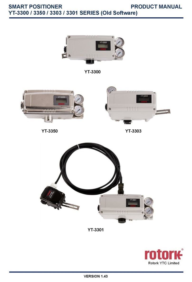
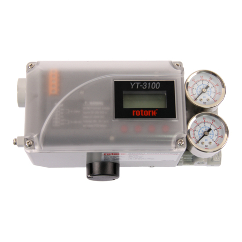
Smart Positioner
YT-3700 / 3750 / 3702 Product Manual
Ver. 1.26 3
4.4.1 Single acting actuator .................................................................................................................... 39
4.4.2 Double acting actuator................................................................................................................... 40
5Connection – Power ................................................................................................................................ 41
5.1 Safety................................................................................................................................................. 41
5.2 Connection......................................................................................................................................... 42
5.2.1 Standard Terminals ....................................................................................................................... 42
5.2.2 Terminals with micro-limit switch option (Only YT-3700 / 3750) ................................................... 44
5.2.3 Terminals with inductive proximity Limit Switch option (Only YT-3700 / 3750)............................. 45
5.3 Ground............................................................................................................................................... 45
6Adjustments ............................................................................................................................................. 46
6.1 Limit Switch Adjustment (Only YT-3700 / 3750)................................................................................ 46
6.2 A/M switch adjustment....................................................................................................................... 47
6.3 Orifice Installment.............................................................................................................................. 48
7Optional Sub-PCB Installment ............................................................................................................... 49
7.1 Installation steps................................................................................................................................ 49
8Maintenance ............................................................................................................................................. 51
8.1 Supply air........................................................................................................................................... 51
8.2 Seals.................................................................................................................................................. 51
9Auto Calibration and PCB Operation..................................................................................................... 52
9.1 Warning.............................................................................................................................................. 52
9.2 LCD display and buttons.................................................................................................................... 52
9.2.1 LCD display and symbols.............................................................................................................. 52
9.2.2 Button and function........................................................................................................................ 53
9.3 Menu levels........................................................................................................................................ 54
9.4 RUN Mode Monitor............................................................................................................................ 55
9.5 Configuration and Operation.............................................................................................................. 56
9.6 Calibration (CALIb) ............................................................................................................................ 60
9.6.1 Acting Type (SINGLE / dOUBLE).................................................................................................. 60
9.6.2 Auto Calibration 1 (AUTO 1).......................................................................................................... 61
9.6.3 Auto Calibration 2 (AUTO 2).......................................................................................................... 61
9.6.4 Travel Zero (TVL ZERO) and Travel end (TVL ENd).................................................................... 62
9.7 Manual Operation (MAN OPER)........................................................................................................ 63
9.7.1 Manual Operation by Set position (MAN SP) ................................................................................ 63
9.7.2 Manual Operation by Manipulator Value (MAN MV) ..................................................................... 64
9.8 Control Parameters (CTL PARM)...................................................................................................... 65
9.8.1 Dead Band (dEAdbANd)................................................................................................................ 65
9.8.2 Forward P parameter (KP UP) and reverse P parameter (KP dN)................................................ 66
9.8.3 Forward Integral time parameter (TI UP) and reverse Integral time parameter (TI dN)................ 66
9.8.4 Forward D parameter (Kd UP) and reverse D parameter (Kd dN)................................................ 67
9.8.5 GAP parameter (GAP)................................................................................................................... 67
