Kingspan SHE TRZ Plus 2A User manual

Kingspan
SHE Control Panel TRZ Plus 2A
and TRZ Plus Comfort
Technical Manual
Compact Control Panel 2A and Compact Control Panel 2A/M
Light + Air
UK & Republic of Ireland

2 Technical ManualKingspan SHE Control Panel TRZ Plus
2A and TRZ Plus Comfort
Contents
Page
Equipment Overview / Function 3
Scope of Delivery 3
Safety Instructions 4
Routing of Cables 6
Description of Function 7
Cable Length Diagram 9
Cable Cross-Section Determination 9
Possible Connections 10
Connecting Diagram Mains / Connecting Diagram Drive 12
Connecting Diagram Magnetic Clamps / Magnetic Locking 13
Connecting Diagram Vent Switch 14
Connecting Diagram SHE manual Call Point 15
Connecting Diagram Smoke Detector 16
Connecting Diagram Fire Alarm System 17
Connecting Buzzer / Signal Lamp 18
Connecting Diagram Wind/Rain Detector 19
Connecting Diagram Potential Free Contacts 19
Connecting Selector Switch Manual / Automatic,
Temperature Sensor and Vent Switch 20
Connecting Multisensor for Measurement of Humidity (%),
CO2Quality (ppm) and Temperature (° C) 21
Connection Diagram 22
Function of DIP-Switches 23
Service Port 25
Start Up Procedure and Trial Run 26
Troubleshooting 28
Maintenance 30
Dimensional Drawing 31
Assembly 33
Service Port Software 35
Technical datas 38

3Technical Manual Kingspan SHE Control Panel TRZ Plus
2A and TRZ Plus Comfort
12/24999513
Equipment Overview /
Function
• SHE control panel for opening and closing of smoke vents in case of
reandventilation.
• Control of 24V DC motors with their own load or limit with a total
powerconsumptionofmax.2A.
• Function “daily ventilation”
• One SHE group and one ventilation group
• 24V power supply, emergency power batteries and charging unit,
parallel operation, 72 hours of functioning guaranteed in case of
power failure
• Linemonitoringofalarmcircuits(autom.detectorsandSHEman.
call points)
• Line monitoring of the connected drives
• Optical malfunction alarm
• Separately fused power input 230V AC / 50 Hz
• Hinged door or cover, lockable
• Conforms to current state-of-the-art standards
• Processor controlled
• Versatile connection facilities
• Service port interface included
• TÜV type tested
• Tested according to EN 12101-10
Scope of Delivery
• 1 x SHE control panel
• 1 x rechargeable batteries
• 2 x velcro tapes for fastening the batteries (Compact Control panel
2A, 2A/M)
• 1 x set of operating instructions
TRZ Plus 2A
TRZ Plus 2A Comfort
Compact Control panel 2A
(Plastic housing)
Compact Control panel 2A/M
(M = Metal housing)
Compact control panel 2A and
Compact control panel 2A/M
For smoke heat extraction and daily
ventilation to control 24 V DC linear drives
and chain motors
Pleasekeeptheseoperatinginstructionsforfuturereferenceandmaintenance.Subjecttotechnicalmodications.Diagramisnotbinding.

4 Technical ManualKingspan SHE Control Panel TRZ Plus
2A and TRZ Plus Comfort
12/24999513
Safety Instructions
Documentation: This documentation is exclusively
valid for the product or product range as stated in the
type designation on the cover and must be applied
comprehensively.Thistechnicaldocumentationmustberead
carefullybeforeinstallation.Followtheguidelines.Contact
themanufacturerifyouhaveanyquestionsorproblems.This
documentationshouldberetainedforfuturereference.
User: This documentation is aimed at trained, professional
electricians with safety awareness, who are familiar with
mechanical and electrical equipment installation, accident
prevention regulations and industrial compensation laws,
andcontainsimportantinformationforoperatorsandusers.
Please observe the following safety instructions which are
emphasized by special symbols.
Caution:Dangertopersonsduetoelectricity.
Attention: Danger to persons due to risks arising
fromtheoperationoftheequipment.Dangerof
crushing/trapping.
Warning:Non-observanceleadstodestruction.
Dangertomaterialduetoincorrecthandling.
Important information
Use according to regulations: The product may
only be used for the functions and applications
detailed, and in accordance with the
accompanyingdocumentation.Unauthorised
electricalandmechanicalmodicationsarenot
permittedandwillinvalidatewarrantyandliability.
Transport and storage: The product may only be
transportedandstoredinitsoriginalpackaging.Itmustnot
be knocked, dropped, or exposed to moisture, aggressive
vapoursorharmfulenvironments.Moredetailedtransport
and storage instructions provided by the manufacturer must
beobserved.
Installation: Installation and assembly may only be carried
out by trained professional electricians, in accordance with
the recognised rules of engineering as well as the technical
documentationprovidedhere.Thiswillguaranteethat
theproductwillfunctionsafelyduringoperation.Care
shouldbetakenthatallmechanicalcomponentsarexed.
Immediately after installation the electrical and mechanical
components should be checked to ensure that they function
correctly, and the tests and the results thereof should be
documented.
Operation: Safe operation is guaranteed if the acceptable
rated values and guidelines regarding maintenance
information stated in this documentation, as well as
supplementary information provided by the manufacturer,
arefollowed.
Malfunction:Ifamalfunctionisidentiedinthecourseof
installation,maintenance,inspectionetc.,immediateaction
shouldbetakentorectifytheproblem.
Repair and maintenance: Defective equipment must
only be repaired by the manufacturer, or by companies
authorisedbythemanufacturer.Onlyoriginalspare
partsmaybeused.Repairsmayonlybecarriedoutby
trained professional electricians, in accordance with the
recognised rules of engineering as well as the technical
documentation provided here and supplementary advice
fromthemanufacturer.Thiswillguaranteethattheproduct
willfunctionsafelyduringoperation.Careshouldbetaken
thatallmechanicalcomponentsarexed.Immediatelyafter
repair the electrical and mechanical components should be
checked to ensure that they function correctly, and the tests
andtheresultsthereofshouldbedocumented.
Maintenance: If the product is used as part of a safety
system such as a smoke and heat extraction system (SHE),
it must be tested, maintained and if necessary repaired at
leastonceayearasspeciedbythemanufacturerorin
line with EN 18232-2 Smoke and heat control systems for
instance and The Regulatory Reform (Fire Safety) Order
2005.Thisisalsorecommendedforsystemsusedpurely
forventilation.Iftheproductistobeusedinothersafety
systems,shortermaintenanceintervalsmaybenecessary.
With systems composed of control units, opening devices,
controlsectionsetc.,allcomponentsthatinteractdirectly
witheachotheraretobeincludedinmaintenance.
Maintenance must be carried out comprehensively following
the manufacturer guidelines and the accompanying
documentation.Componentsrequiringmaintenancemust
beaccessible.Defectiveequipmentmustonlyberepaired
by the manufacturer, or by companies authorised by the
manufacturer.Onlyoriginalsparepartsmaybeused.All
componentsthathaveaspeciedmaximumoperationtime
(such as batteries) must be replaced within this time (see
technicalspecication)withoriginalpartsormanufacturer-
approvedparts.Regularinspectionisnecessarytoensure
thattheequipmentisreadyforoperation.Amaintenance
contractwitharecognisedcontractorisrecommended.

5Technical Manual Kingspan SHE Control Panel TRZ Plus
2A and TRZ Plus Comfort
12/24999513
Safety Instructions
Disposal: Packaging is to be disposed of
appropriately.Electricalequipmentistobedisposed
of at recycling collection points for scrap electrical
andelectronicequipment.TheElectricalandElectronic
Equipment Act relating to disposal of electrical equipment
doesnotapplyinthisinstance.Rechargeableandsingle-use
batteries are to be disposed of in line with § 18 of the Battery
Ordinance and local environmental laws, either via the
manufactureroratanappropriatecollectionpoint.Electrical
equipment and batteries must not be disposed of with
householdwaste.
Compatibility: When putting together a system consisting
ofvariousdevicesmadebydierentmanufacturers,the
system compatibility must be tested and approved by
theconstructortoensuresafefunctionduringoperation.
Equipmentmodicationtoachievecompatibilitymustbe
authorisedbythemanufacturer.
Conformity:Thisconrmsthattheequipmentcomplieswith
therecognisedrulesofengineering.Forelectricalequipment
a declaration of EC conformity can be requested from the
manufacturer.Note:iftheequipment(e.g.driveunit)ispart
of a machine in terms of the Machinery Directive 2006/42/
EC, this does not render the supplier/contractor exempt
from informing the customer with regard to the necessary
installation instructions, labelling, documentation and
certicatesrelevanttothisdirective.
Guarantee: The ZVEI “Green Supply Conditions” are taken
asagreed.Theguaranteeperiodformaterialsupplyis12
months.Anyinterventionwiththeequipmentorsystem
that is not authorised by the manufacturer will result in i
nvalidationofliability,guaranteeandservice.
Liability:Productchangesandsettingsmaybemodied
withoutadvancenotice.Illustrationsarenotbinding.No
liability will be held for contents despite maximum care being
taken.
Electrical safety
Wiring and electrical connections must only be done by an
electrician.Mains230/400VACmustbesecuredseparately
onsite.Theappropriatelaws,specicationsandstandards
mustbeobserved,suchasthedirectiverelatingtore
safety of conduit installations (MLAR / LAR / RbALei), VDE
0100(specicationsforhigh-voltagecircuitsupto1000V),
VDE0815(installationcablesandwiring),VDE0833(re,
burglaryandattackalarmsystems).Ifnecessary,cable
typesmustbedenedinconjunctionwiththelocalapproval
bodies,powersupplycompaniesorresafetyauthorities.
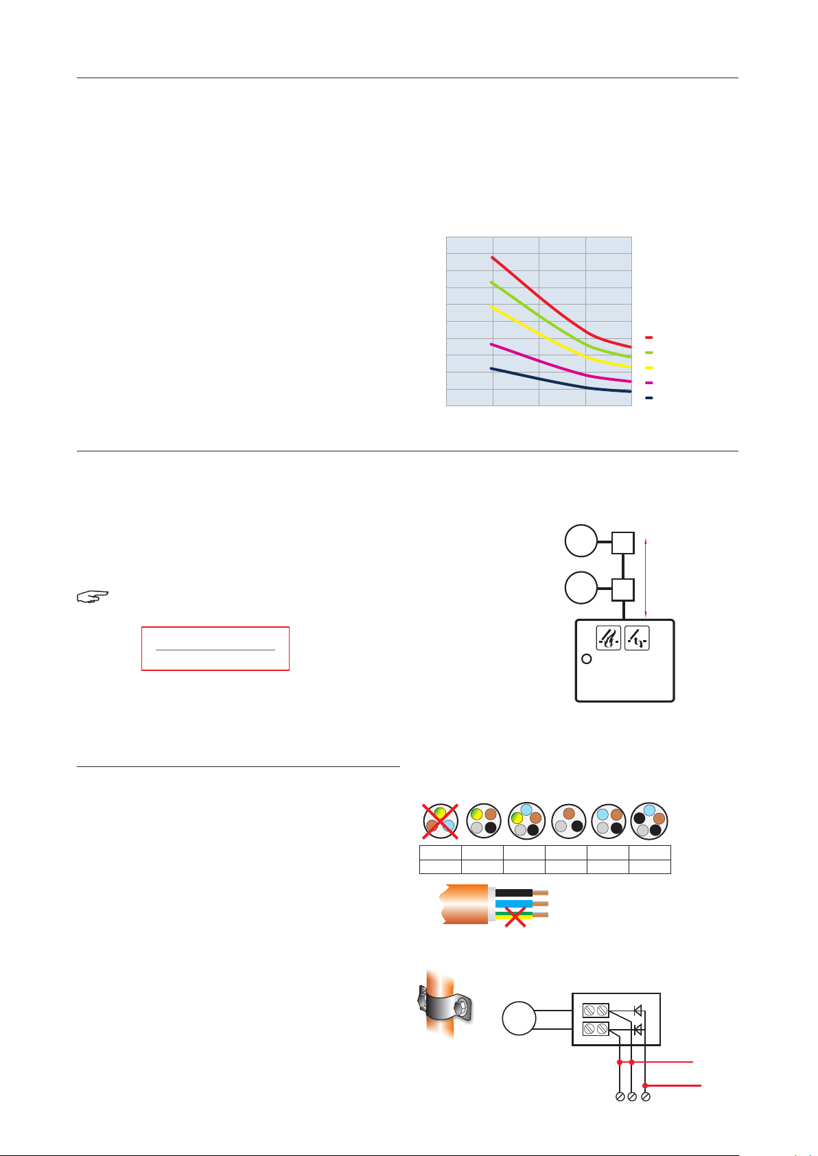
Cablingforextra-lowvoltages(e.g.24VDC)istobelaid
separatelyfromlow-voltageline(e.g.230VAC).Flexible
cables must be laid in such a way that they cannot be
shearedo,twistedorsnappedduringoperation.Power
supplies,controlunitsandjunctionboxesmustbeaccessible
formaintenancework.Cablingtypes,lengthsandcross-
sectionsaretocomplywithtechnicalguidelines.
Before work is carried out on the system, the
mainscurrentandemergencypowersupply(eg.
rechargeable batteries) is to be disconnected from all-
polesandsecuredtopreventaccidentalswitch-on.Never
operate the drive units, control units, operator elements and
sensors on supply voltage and connections in such a way as
tocontravenetheguidelinesintheoperatormanual.There
isariskoffatalinjury,anditcancausecomponentstobe
destroyed!
Mechanical Safety
Falling window casements: Window casements are to be
mounted in such a way that even if one of the suspension
elements fails, the design prevents the unit from falling or
movinginanuncontrolledway,e.g.bydoublehanging,
securitystay,safetycatch.Pleasenote:toprevent
obstruction/falling of the window, the security stay/safety
catch must be compatible with the intended opening span
andmechanismofthewindow.Seealsothedirectivefor
power-operated windows, doors and gates (BGR 232) and
the ZVEI brochure “SHEUpdateNo.3,power-operated
windows“.
Fittings and xing material:anyxingmaterialsrequiredor
supplied with the product must be adapted to the building
andload,andifnecessarysupplemented.
Crush and shear points:Power-operated windows,
doorsandgates:Anycrushandshearhazardareas,
fo r instance between the casement and frame or
skylight and base, must be secured against trapping using
appropriatemeasurestopreventinjury.Seealsothedirective
for power-operated windows, doors and gates (BGR 232)
andtheZVEIbrochure“SHEUpdateNo.3,power-operated
windows“.
Accident prevention regulations and industrial
compensation laws: For works to, on or in a building or part
thereof, the appropriate accident prevention regulations
(UVV) and industrial compensation laws (BGR) are to be
observed.
Environmental conditions: The product must not be
knocked, dropped, or exposed to vibration, moisture,
aggressive vapours or harmful environments, unless
the manufacturer has authorised one or more of these
environmentalconditions.

6 Technical ManualKingspan SHE Control Panel TRZ Plus
2A and TRZ Plus Comfort
I-Y(St)Y 2x2x0,8 mm, max. 100 m
I-Y(St)Y 4x2x0,8 mm, max. 100 m
I-Y(St)Y 2x2x0,8 mm, max. 100 m
I-Y(St)Y 4x2x0,8 mm
!
I-Y(St)Y 2x2x0,8 mm, max. 100 m
I-Y(St)Y 4x2x0,8 mm, max. 100 m
I-Y(St)Y 2x2x0,8 mm, max. 100 m
I-Y(St)Y 4x2x0,8 mm
!
I-Y(St)Y 2x2x0,8 mm, max. 100 m
12/24999513
Routing of Cables
Note:Thisisawiringexample.
Note:Makesureallcabletypesandspecicationsareaccordingtositemanagementrequirementsandthe
appropriatenationalandlocalcodesandlaws.Thestatedcablecrosssectionsmustnotbereduced.Theyarelistedforan
ambienttemperatureof20°C.Increasethecrosssectionsforhighertemperatures.ForE90(E30),allcablecrosssections
mustbeadaptedtothemanufacturer’sspecications.Allcablestothecontrolpanel(exceptthemainssupplylead)
carry24VDCandmustberoutedseparatelyfromthemainssupplylead.Whenroutingthecables,pleaseobservethe
correspondingVDEregulations.
* with expansion via additional printed circuit board TRZ-WRMAS-Basic by TRZ Plus Comfort
Seren 24 V AC /DC 100 mA
Cable type (see chapter cable length diagram)
Protective conductor cable may NOT be used!
Observe VDE regulations!
Either magnetic locking 24 V DC or linear drives
junctionbox
(lastjunctionboxwithmonitoringdiodes)
(see note)
Mains 230V /50 Hz
NYM-I3x1.5mm
Provideaseparatelydisengageablecircuit.
Secureagainstunintentionalswitching-o.
Transmission*
SHE call point
(last SHE manual
call point with
end module)
Vent switch
(see note)
(see note)
(see note)
automatic alarm unit
(last alarm unit with
end module)
up to 200 m I-Y(St)Y 2x2x0,8 mm
up to 350 m I-Y(St)Y 2x4x0,8 mm
Linear drives M9,
24VDC,max.1amp
(withintegratedpowercut-o)
Magnetic locking 24V DC
Wind/rain detector 24 V AC /DC 100 mA*
or TRZ Plus 2A
or TRZ Plus Comfort
detector circuit1
Compact Control panel 2A
Compact Control panel 2A/M
Temperature
sensor
Selector switch
manual/auto-
matic

7Technical Manual Kingspan SHE Control Panel TRZ Plus
2A and TRZ Plus Comfort
12/24999513
Description of Function
Universally
Smoke-Heat-Extraction- (SHE) and Ventilation control panel
for24VDCdriveswithamaximumCurrentdrawof2A.
Toopenandcloseaps,windows,skylightdomesandfor
smokeextractionanddailyventilation.SHEandventilation
functionsviamanualandautomatedcontroldevices.
Self-monitoring system with malfunction indication via LED
ashlight.Integratedpowerbackupfor72haccordingto
DINEN12101-10andVdS2593.SHE-functionsaccordingto
prEN12101-9andVdS2581.Extendedfunctionsforusein
elevatorshaftsaccordingtoVdSguideline2895.Electrical
safetywithTÜVapproval.Installedwithinplasticormetal
housingavailableforsurfaceorinushmountedversionwith
additionalushmountingset.
Manual activation in case of re/smoke/
alarm
Smoke heat extraction / opening windows
Press the red Open switch at a SHE manual call point,
the windows open completely, the red LED display -
SHE activated - is shining at all SHE manual call points, the
ventilationfunctionisoutoforder.
Smoke heat extraction / closing windows
Press the switch “Closed” at a SHE manual call point, the
windows are closing, the red LED display - SHE activated
- goes out at all SHE manual call points, the ventilation
functionisworkingagain.
Note: There is no Reset of the connected and
activated automatic detectors!
Automatic activation in case of re/smoke/
alarm
(If automatic detectors are connected only)
Smoke heat extraction / opening windows
Smoke reaches the automatic detectors, the windows are
opened completely, the red display in the automatic detector
is shining, the red LED display - SHE activated - is shining
at all SHE manual call points, the ventilation function is out
oforder.
Smoke heat extraction / closing windows
Press the switch “Closed” at a SHE manual call point, the
windows are closing, the red LED display - SHE activated
- goes out at all SHE manual call points, the yellow LED
display -malfunction-ashes.
Note: there is no Reset of the connected and
activated automatic detectors!
Reset of automatic detectors
Set the automatic detectors free from smoke by blowing out
orreplacethemincaseofheavysoiling.
Press the Reset switch on the basic circuit control board of
the control panel, the windows are closing, the red display
in the automatic detectors goes out, the red LED display
- SHE activated - goes out at all SHE manual call points,
the yellow LED display - malfunction - goes out, the
ventilationfunctionisworkingagain.
Daily ventilation
(If vent switches are connected only respectively via
operating element of the TRZ Plus Comfort)
Opening windows
Press the switch “Open” at the vent switch, the windows
opencompletely.(Interruptionoftheopeningbypressing
both switches together (Open and Closed) = STOP or by Stop
switchdependingonventswitch).
Closing windows
Press the switch “Closed” at the vent switch, the windows
closecompletely.(Interruptionoftheopeningbypressing
both switches together (Open and Closed) = STOP or by
Stopswitchdependingonventswitch).Incaseofmainsor
batteryfailure,thewindowscloseimmediately.

8 Technical ManualKingspan SHE Control Panel TRZ Plus
2A and TRZ Plus Comfort
12/24999513
Description of Function
Automatic Ventilation Control
If activated (see start up procedure), the windows are
closing automatically after xx min (10 min factory-
made), in case of mains or battery failure, the windows
closeimmediately.
Seealsopage25,DIP-Switch12.
Mains or battery failure
-Automaticclosingoftheaps
- Ventilation function locked, SHE function active
Note: These are standard features for mains or
batteryfailure,Specialfunction:seeDIPswitch
function 3 + 10
Extraction Limit (by operating time)
Seenoteonpage62,switchDIP-Switch6toON.
Teaching
Closethewindows.Earlieststartofthelearningmode
after30seconds.Presstheswitches“Open”and“Closed”
(STOP) at the vent switch as long as the display “Open” is
ashingfast.Openthemotorwiththeswitch“Open”up
tothepositionrequiredwithinthenext10sec.andstop
themotorinthispositionbyreleasingtheswitch“Open”.
Ifnootherswitchispressedwithinthenext10sec.the
learningphaseisnished.
To Deactivate
Seenoteonpage20,switchDIP-Switch6toOFF.
Note: If the vent switch has no Open-display or
there is no ventilation button in the door of the
TRZ-Plus Comfort the stroke limit setting must be
madethroughtheoptionalserviceportsoftware.
Note: In case of mains or battery failure or SHE
activationthefunctionisoutoforder.Incase
of mains or battery failure, the windows close
immediately.
LED Display
IntheSHEcontrolpanelandSHEmanualcallpoints.
The green LED display
OK
-operatingOK-isshining.It
goesoutincaseof:
- mains or battery failure
- malfunction of the line monitoring of the connected
drives,automaticdetectorsorSHEmanualcallpoints.
The yellow LED display -malfunction-isashingin
caseof:malfunction,cableconnectiondefective,mains
and/orbatteryfailure.
Caution: If any malfunction is indicated the
malfunctionhastobeeliminatedimmediately.
The perfect function of the system is no longer
guaranteed.
The red LED display - SHE activation - is shining in
caseof:manualorautomaticSHEactivation.
Closing with Wind/Rain Detector
If a wind/rain detector or a rain sensor is connected, the
windows close automatically in case of beginning winds
and/orrainfall,“VentilationOpen”displayashes,vent
switchoutoforder.Thewindowscloseimmediatelyin
caseofpowerorbatteryfailure.
Note: The ventilation function is out of order or
locked in case of power or battery failure or SHE
activationinordertosavebatterypower.

9Technical Manual Kingspan SHE Control Panel TRZ Plus
2A and TRZ Plus Comfort
12/24999513
Cable Length Diagram
To determine the necessary cable cross-sections as a
function of the line length and the sum of the rated currents
ofthedrives.
m (simple line length)
Cablelengthdiagramupto2ampsfordriveswithacurrentdraw<2.5A
0
1 2
a)
b)
c)
d)
e)
e) 6 mm²
d) 2 x 2,5 mm²
c) 4 mm²
b) 2,5 mm²
a) 1,5 mm²
50
100
150
200
250
300
350
400
450
500
Nominal drive current in amps
Cable Cross-Section Determination
Notes re-cable cross-section determination and cabling layout
Simpliedformulaeforcablecross-sectiondetermination(fordrivesupto2.5
A nominal current draw)
Note: Permissible current supply of the TRZ Plus has to be considered,
seetechnicaldata.
A = cable cross-section
I = sum of the rated drive current draws
*L = simple line length
73=factor,madeupfrom2.5Vmax.permissiblevoltagedropandelectricalconductivityofcopper
A [mm²] =
*
(I [A] + ggf. Aufschlag in %**) x L [m]
73
A [mm²] =
*
(I [A] +
if so loading factor in %**
) x L [m]
73
A [mm²] = I [A] x L* [m]
73
M
=
M
=
simple cabel
length(L*)
Notes re-selection of cables
For the motor supply cables of SHE drives 3 or 5 (duplicated
layout)individualcoresarerequired.
Two cores (4 cores) are for the motor voltage, the 3rd or 5th
corerespectivelyisrequiredformonitoringthecabling.
The selection and layout of the cables is to be performed
accordingto(model)utilityfacilitiesguidelines(MLAR).Here
particular attention is to be paid to E30 or E90 functionality
retention!
3 x ... mm²
**
5 x ... mm²
3 x ... mm²
**
5 x ... mm²
M
=
yellow-green:cannotbeusedfor
the calbing monitoring
brown
blue
Motor Junction box
Motor voltage
Cabling monitoring
Cabling example
Examples of cable types and ttings that can be used
Cable system, consisting of load support system and cables
withappropriatereprotectiontestedwallplugsand
screws.CablesysteminaccordancewithDIN4102-12and
BS8519.Safetycable+layoutsystem

10 Technical ManualKingspan SHE Control Panel TRZ Plus
2A and TRZ Plus Comfort
12/24999513
RESET
- +
!
OK
ON
OFF
57 8
1 3 6 10 1
1
2
4 9 1 2
STG-B.
Port
230 V AC
STOP
Lüftung/VENT Rauchabzug
Smoke heat extraction
12V
M1
=
L1 N 1
12V
M1
=
2 3 8910 1112131415 16171819 20 21
Possible Connections
- lineardrives24VDCwithintegratedelectronicpowercut-o,tandempowercut-o,synchromoduleorchainmotors
24 V DC with limit switches
- overallpowerconsumptionofallmotorsconnectedmax.2A
- 10SHEmanualcallpointsRBH/3A...(lineterminationviaenclosedendresistance)
- 10automaticdetectorswith2-wire-technology,opticalsmokedetectorsand/ordetectorsofheatdierentialand/or
detectorsofmaximumheatormonotoringresistorexfactoryviathenalfuseattached
- 10externalventilationswitches“Open/Stop/Closed”(e.g.typeLTA25)
- 24VDCsirenorashinglights,max100mA
- toconnect1wind-/raindetector(e.g.typeWRM24V,WRM2)or1raindetector(e.g.RM,RM2)OnlywithTRZPlus
ComfortorwithadditionalmoduleWRMAS.
- in each case one connection for potential-free report SHE activated (NO= normally Open contact) and malfunction
(NC=normallyclosedcontact):24V/max.0.5A
OnlywithTRZPlusComfortorwithadditionalmoduleWRMAS.
Fuse
F2 Motor
Switch "SHE Closed" Reset
DIP-Switch
PC Service Port
Fuse battery
Battery connection
Fuse
F1 mains
LED display
F3 battery
Extension ledge
Additional modules connection
The extension by the additional module TRZ/WRMAS* and
TRZRBH*areanoption,itisnotpartofthestandardsupply.
Pleaseaskyourdistributorifrequired.
1. Wind-rain-detection-alarm-malfunction
(TRZ/WRMAS-Basic)
Thefollowingcomponentscanbeconnected:
1 x connection wind/rain detector or rain detector
1xpot.-freetransmissionAlarm(SHE-activation),Closing
contactmax.30VDC/0.5A
1xpot.-freetransmissioncollect.malfunction,Opening
contactmax.30V/0.5A
Opening contact
collective malfunction
Closing contact
alarm (SHE)
Extension ledge
!
456720212223
TRZ/WRMAS
* standard included in the TRZ Comfort Plus

11Technical Manual Kingspan SHE Control Panel TRZ Plus
2A and TRZ Plus Comfort
12/24999513
Installation
Disconnect the control panel from power supply (mains and battery), plug the spacer to the principal circuit control board,
plug the additional module to the extension ledge, create the desired connections and check, re-establish power supply
(mainsandbattery).
Check wind/rain detection function
No SHE and no malfunction signal, the green LED
OK
operatingisshining.PresstheswitchOpenattheventswitch,the
motoropens.Moistentherainsensorsurfaceoftheweatherdetector,thedrivesclose.Iftheventswitchhasadisplayfor
Open,itashes.Theventilationfunctionisblockedaslongasawindorrainalarmispending.ActivateSHE - the drives
havetoopenduringapendingwindorrainalarm(SHEhaspriority).Totestthewinddetection,apermanentaircurrenthas
tobedetectedatthewindwheelapprox.3min(e.g.ahairdryer).Otherwiseproceedforthecheckingasdescribedabove.
Check Alarm (SHE) and malfunction function
No SHE and no malfunction detection, green LED
OK
-operating-isshining.ActivateSHE .Theclosingcontactatthe
terminals4+5switches.ThefunctionisOKifthepassagecanbemeasured.ActivateSHEClosed , initial position, no
SHE-activationandnomalfunctiondetection.TakeothebatteryfuseF3tosimulateamalfunction,Activation!Replace
fuseF3back,controlpanelagainininitialposition,repeatcompletebringingintoserviceoftheTRZPlus2A.Noerrors,
functionisOK,systemreadyforoperation.
2. SHE manual call point TRZ/RBH-Basic
integratedintheTRZPlusfrontdoor.Notsuitableforcompactcontrolpanel2Aand2A/M.
Possible Connections
LED-display
Extension ledge
Switch SHE-activation
SHE manual call point TRZ/RBH
Switch SHE Closed (no Reset)
OK
!
Installation
Disconnect power supply (mains and battery), mount additional module at the inside of the control panel door, plug the plug
totheextensionledgeoftheprincipalcircuitcontrolboardor,ifavailable,oftheadd.moduleTRZ/WRMAS,reconnectpower
supply(mainsandbattery).
Function check
Proceedasindicatedpage65,point“SHEman.callpoints“,repeatthecompletebringingintoserviceoftheTRZPlus,no
errors,functionOK,systemisreadyforoperation.

12 Technical ManualKingspan SHE Control Panel TRZ Plus
2A and TRZ Plus Comfort
12/24999513
1 2 3
M
=
1 2 3
24 V DC
24 V DC
1 2 3
-+
-
+
M
=
M
=
M
=
M
=
M
=
Connecting Diagram Mains/Connecting
Diagram Drive
Allworktobecarriedoutwithoutmainssupply(230VAC)oranybatteriesconnected.Routetheconnectingcablesinto
thecontrolpanelhousingatthetop.Connectallconnectingcablesaccordingtothewiringdiagramandmakesurethat
theyarecorrectlyconnected.Incorrectconnectionsorgureorcolourmix-upscanleadtoincorrectfunctionofthecontrol
paneloroftheexternalcomponents.Thenotesandinstallationdirectivesinthetechnicaldocumentationarealwaystobe
observed.
Provideaseparatelydisengageablecircuit.
Secureagainstunintentionalswitching-o.
several drives per motor circuitone drive
brown
blue
junctionbox junctionbox
last drive
brown
blue
1.drive
brown
blue
monitoring diodes
one drive
N
L1 PE
N
L1 PEPE
Connecting diagram mains (230V AC)
Connecting diagram drive

13Technical Manual Kingspan SHE Control Panel TRZ Plus
2A and TRZ Plus Comfort
1 2 3
+
-
1 2 3
+
-
+
-
-
+
-
+
-
+
O V DC
24 V DC + -
1
2
1 2 3
O V DC
24 V DC + -
1 2 3
12/24999513
Allworktobecarriedoutwithoutmainssupply(230VAC)oranybatteriesconnected.Routetheconnectingcablesintothe
controlpanelhousingatthetop.Connectallconnectingcablesaccordingtothewiringdiagramandmakesurethattheyare
correctlyconnected.Incorrectconnectionsorgureorcolourmix-upscanleadtoincorrectfunctionofthecontrolpanelorof
theexternalcomponents.Thenotesandinstallationdirectivesinthetechnicaldocumentationarealwaystobeobserved.
Connecting Diagram Magnetic Clamps/
Magnetic Locking
Magnetic locking*
one magnetic clamp /magnetic locking
Magnetic clamp*
Magnetic locking*
Magnetic clamp*
several magnetic clamps /magnetic lockings
Junction box Junction box
Magnetic clamp
Monitoring diodes
Last Magnetic clamp
Magnetic clamp 1
2 Closing via spring force of the
door closer
Window closed
The door is
kept open by
magnetic clamp
1Opening via spring force of the
gas spring
* see page 61, DIP-Switch 3 = ON

14 Technical ManualKingspan SHE Control Panel TRZ Plus
2A and TRZ Plus Comfort
10/13424999756
S
SP
POO
11 10 8
STOP
4 3 2 1
4 3 2 1
STOP
STOP
STOP
SS PP OO
SS PP OO
11 10 8 811 10 9
4 3 2 1
811 10 9
S
SP
POO
11 10 8
STOP
4 3 2 1
4 3 2 1
STOP
STOP
STOP
SS PP OO
SS PP OO
11 10 8 811 10 9
4 3 2 1
811 10 9
Allworktobecarriedoutwithoutmainssupply(230VAC)oranybatteriesconnected.Routetheconnectingcablesinto
thecontrolpanelhousingatthetop.Connectallconnectingcablesaccordingtothewiringdiagramandmakesurethat
theyarecorrectlyconnected.Incorrectconnectionsorgureorcolourmix-upscanleadtoincorrectfunctionofthe
controlpaneloroftheexternalcomponents.Thenotesandinstallationdirectivesinthetechnicaldocumentationare
alwaystobeobserved..
Connecting Diagram Vent Switch
one vent switch LTA11 one vent switch LTA25
Jumper
Jumper
several vent switch LTA11 several vent switch LTA25
Jumper
last vent switch last vent switch

15Technical Manual Kingspan SHE Control Panel TRZ Plus
2A and TRZ Plus Comfort
12/24999513 53
Connecting Diagram SHE Manual Call Point
without SHE manual call point one SHE manual call point several SHE manual call points
12 13 14 15 16 17
3
58
426
1
OK
!
10kΩ
OK
!
RBH/3A
10kΩ
12 13 14 15 16 17
6
5483
1
6
5483
1
12 13 14 15 16 17
3
58
426
1
OK
!
10kΩ
RBH/3A
OK
!
RBH/3A
RBH/3A
Allworktobecarriedoutwithoutmainssupply(230VAC)oranybatteriesconnected.Routetheconnectingcablesintothe
controlpanelhousingatthetop.Connectallconnectingcablesaccordingtothewiringdiagramandmakesurethattheyare
correctlyconnected.Incorrectconnectionsorgureorcolourmix-upscanleadtoincorrectfunctionofthecontrolpanelorof
theexternalcomponents.Thenotesandinstallationdirectivesinthetechnicaldocumentationarealwaystobeobserved.
Monitoring resistor
10kΩ

16 Technical ManualKingspan SHE Control Panel TRZ Plus
2A and TRZ Plus Comfort
12/24999513
Connecting Diagram Smoke Detector
Allworktobecarriedoutwithoutmainssupply(230VAC)oranybatteriesconnected.Routetheconnectingcablesintothe
controlpanelhousingatthetop.Connectallconnectingcablesaccordingtothewiringdiagramandmakesurethattheyare
correctlyconnected.Incorrectconnectionsorgureorcolourmix-upscanleadtoincorrectfunctionofthecontrolpanelorof
theexternalcomponents.Thenotesandinstallationdirectivesinthetechnicaldocumentationarealwaystobeobserved.
without smoke detector one smoke detector
SSD 521
UTD 521
UTD 523
MSD 523
last smoke detector
several smoke detectors
SSD 521
UTD 521
UTD 523
MSD 523
one
smoke
detector
last smoke detector
last
smoke
detector
1.smoke
detector
18 19
10kΩ
18 19
+
+123456
123456
10kΩ
123456
+
123456
10kΩ
18 19
123456
+
+
18 19
+
+
18 19
+
10kΩMonitoringresistor
tillFirmwareV01.00.11:DIP-Switch11=OFF
fromFirmwareV01.00.12:DIP-Switch11=ON
active end modul /2
tillFirmwareV01.00.11:DIP-Switch11=ON
fromFirmwareV01.00.12usedasstandard:DIP-Switch11=OFF
10kΩ

17Technical Manual Kingspan SHE Control Panel TRZ Plus
2A and TRZ Plus Comfort
1k
2
4
1
3
UEB2-AE/2
18 19
10kΩ
t ~ 2 sec*.
FAS
UEB2
t ~ 2 sec.*
BMA
+
BMA
BMA
ABA
D
GB
DK
18 19
+1k
2
4
1
3
UEB2-AE/2
UEB2UEB2UEB2
UEB2UEB2UEB2
UEB2-AE/2
UEB2UEB2UEB2UEB2
UEB2UEB2UEB2
UEB2-AE/2
18 19
+
12 3456
18 19
+
+
18 19
10kΩ
t ~ 2 sec.
FAS
UEB2
t ~ 2 sec.
+
BMA
ABA
D
GB
DK
18 19
+
1k
2
4
1
3
UEB2-AE/2
UEB2UEB2UEB2
UEB2UEB2UEB2UEB2
UEB2UEB2UEB2
18 19
+
UEB3-1K-AE
UEB3-1K-AE
UEB2UEB2UEB2
UEB3-1K-AE
18 19
+
1k
2
4
1
3
UEB2-AE/2
18 19
10kΩ
t ~ 2 sec*.
FAS
UEB2
t ~ 2 sec.*
BMA
+
BMA
BMA
ABA
D
GB
DK
18 19
+1k
2
4
1
3
UEB2-AE/2
UEB2UEB2UEB2
UEB2UEB2UEB2
UEB2-AE/2
UEB2UEB2UEB2UEB2
UEB2UEB2UEB2
UEB2-AE/2
18 19
+
12 3456
18 19
+
+
18 19
10kΩ
t ~ 2 sec.
FAS
UEB2
t ~ 2 sec.
+
BMA
ABA
D
GB
DK
18 19
+
1k
2
4
1
3
UEB2-AE/2
UEB2UEB2UEB2
UEB2UEB2UEB2UEB2
UEB2UEB2UEB2
18 19
+
UEB3-1K-AE
UEB3-1K-AE
UEB2UEB2UEB2
UEB3-1K-AE
18 19
+
12/24999513
Connecting Diagram Fire Alarm System (FAS)
Allworktobecarriedoutwithoutmainssupply(230VAC)oranybatteriesconnected.Routetheconnectingcablesintothe
controlpanelhousingatthetop.Connectallconnectingcablesaccordingtothewiringdiagramandmakesurethattheyare
correctlyconnected.Incorrectconnectionsorgureorcolourmix-upscanleadtoincorrectfunctionofthecontrolpanelorof
theexternalcomponents.Thenotesandinstallationdirectivesinthetechnicaldocumentationarealwaystobeobserved.
without re alarm system with re alarm system with re alarm system and smoke detectors
10kΩMonitoringresistor
tillFirmwareV01.00.11:DIP-Switch11=OFF
fromFirmwareV01.00.12:DIP-Switch11=ON
active end modul /2
tillFirmwareV01.00.11:DIP-Switch11=ON
fromFirmwareV01.00.12usedas
standard:DIP-Switch11=OFF
10kΩ
SSD 521
UTD 521
UTD 523
MSD 523
FAS
BMA
ABA
D
GB
DK
18 19
10kΩ
t ~ 2 sec.
FAS
UEB2
t ~ 2 sec.
BMA
+
BMA
BMA
ABA
D
GB
DK
18 19
+
1k
2
4
1
3
UEB2-AE/2
UEB2UEB2UEB2
UEB2UEB2UEB2UEB2
UEB2UEB2UEB2
18 19
+
UEB3-1K-AE
UEB3-1K-AE
UEB2UEB2UEB2
UEB3-1K-AE
18 19
+
UEB3-1K-AE
isusedfromFirmware1.00.11
and replaces the UEB2-AE / 2
UEB3-1K-AE FAS
FAS
*
*
UEB3-1K-AE

18 Technical ManualKingspan SHE Control Panel TRZ Plus
2A and TRZ Plus Comfort
12/24999513
Connecting Buzzer/Signal Lamp
Allworktobecarriedoutwithoutmainssupply(230VAC)oranybatteriesconnected.Routetheconnectingcablesintothe
controlpanelhousingatthetop.Connectallconnectingcablesaccordingtothewiringdiagramandmakesurethattheyare
correctlyconnected.Incorrectconnectionsorgureorcolourmix-upscanleadtoincorrectfunctionofthecontrolpanelorof
theexternalcomponents.Thenotesandinstallationdirectivesinthetechnicaldocumentationarealwaystobeobserved.
with alarm-buzzer
with alarm-signal lamp
20 21
+ -
+ 24 V -
20 21
+ -
+ 24 V -

19Technical Manual Kingspan SHE Control Panel TRZ Plus
2A and TRZ Plus Comfort
12/24999513
Connecting Diagram Wind/Rain Detector
Connecting Diagram Potential Free Contacts
Allworktobecarriedoutwithoutmainssupply(230VAC)oranybatteriesconnected.Routetheconnectingcablesintothe
controlpanelhousingatthetop.Connectallconnectingcablesaccordingtothewiringdiagramandmakesurethattheyare
correctlyconnected.Incorrectconnectionsorgureorcolourmix-upscanleadtoincorrectfunctionofthecontrolpanelorof
theexternalcomponents.Thenotesandinstallationdirectivesinthetechnicaldocumentationarealwaystobeobserved.
Allworktobecarriedoutwithoutmainssupply(230VAC)oranybatteriesconnected.Routetheconnectingcablesintothe
controlpanelhousingatthetop.Connectallconnectingcablesaccordingtothewiringdiagramandmakesurethattheyare
correctlyconnected.Incorrectedconnectionsorgureorcolourmix-upscanleadtoincorrectfunctionofthecontrolpanelor
oftheexternalcomponents.Thenotesandinstallationdirectivesinthetechnicaldocumentationarealwaystobeobserved.
Attention:Potentialfreecontactsformax.24V/max.0.5amp.
WRM/2 24V
+
-
RM/2 24V
TRZ WRMAS
20 21 22 23
S
1
Ö
2
A
WRM/2 24V
RM/2 24V
3 4 5 6
+-WS 18
18
ON
ON
RM/2 24V
WRM/2 24V
Jumper
1
4
2
3
Wind sensor Relay contact
(NC contact)
switches by SHE activation switches by malfunction message
!
A
S
23
202122
+
-
4
5 6 7 23
202122
+
-
4
5 6 7
A
Ö
TRZ WRMAS TRZ WRMAS
!
A
S
23
202122
+
-
4
5 6 7 23
202122
+
-
4
5 6 7
A
Ö
TRZ WRMAS TRZ WRMAS

20 Technical ManualKingspan SHE Control Panel TRZ Plus
2A and TRZ Plus Comfort
12/24999513 58
Connecting Selector Switch Manual/Automatic,
Temperature Sensor and Vent Switch
Allworktobecarriedoutwithoutmainssupply(230VAC)oranybatteriesconnected.Routetheconnectingcablesintothe
controlpanelhousingatthetop.Connectallconnectingcablesaccordingtothewiringdiagramandmakesurethattheyare
correctlyconnected.Incorrectedconnectionsorgureorcolourmix-upscanleadtoincorrectfunctionofthecontrolpanelor
oftheexternalcomponents.Thenotesandinstallationdirectivesinthetechnicaldocumentationarealwaystobeobserved.
Variant 1 with two temperature sensors:
Adjustablehysteresisforopeningandclosingofwindowsovertherespectivetemperaturesensor.Thefartherapartthe
temperature values , the less unwanted movement commands from the window operators are short-term temperature
changesforexampleDraftsmade.
STOP
4 3 2 1
8
11 10 9
> 20 °C
< 18 °C
á
á
SP
ÖSPÖ
H
A
3
4
4
SPÖ
2°C°C
2 x Temperature sensor TS-1030
Vent switch LTA25 Selector switch WHA-14
manuel automatic
open
open
close
close
SS PP ÖÖ
11 10 8
SP
ÖSPÖ
H
A
°C
3
3
3
á
á
> 20 °C < 20 °C
Vent switch LTA11 Temperature sensor TS-1030
open close
Selector switch WHA-14
manuel automatic
Variant 2 only one temperature sensor:
Automaticopeningandclosingofonetemperaturesensor.Thehysteresisisdeterminedbythesensor(eg1-2°C).
Other manuals for SHE TRZ Plus 2A
1
This manual suits for next models
3
Table of contents
Other Kingspan Control Panel manuals