1011026 User Manual Issue 01 (26.10.2021) 6
General Electrical
7.1.1. General Notes on Outside Electrical Installation
Only qualified and competent persons should carry out any electrical installation. Outside electrical
installations can present dangers that are not usually encountered in internal electrical wiring. External
equipment is subjected to the elements and attention must be made to the suitability of the cable, glands,
connection units etc. for outside use. All cable glands should be IP66, or better. The possibility of attack by
vermin should also be considered and adequate precautions taken.
These notes are not intended to replace the latest I.E.E. Wiring Regulations.
7.1.2. Electrical Supply
The electrical feed should be dedicated to the equipment and not used for any other purpose. The supply
should be via a suitable RCD unit backed up by either a motor rated fuse, or preferably a motor rated MCB of
suitable rating.
Ensure that the blower housing is protected by a suitable RCD to BS 4293 and MCB to BS 3871. Cable
installation below ground should be SWA to BS 6346, unless otherwise stipulated.
The RCD must be of the two-pole type rated at 25A/30mA. (If nuisance tripping is experienced then a
sensitivity of 100mA should be used, but this does reduce the personnel protection capability).
7.1.3. Cable Installation
The type and size of cable depends upon site conditions and distance. If conduit/ducting is possible then
providing mechanical and vermin attack protection is provided, single cables of adequate size can be used.
However, the preferable method would be to use steel wire armoured (SWA) cable. This should be buried in
the ground at a depth of 600mm laid on sand with warning tapes on the cable and an additional tape at a
depth of 150mm.
For loads up to 0.75kW and runs of less than 100 metres, 2.5mm² 3 core SWA is adequate. For loads up to
1.55kW and runs of less than 100 metres, 4.0mm² 3 core SWA should be used. It is a requirement to use the
unused core in the cable for the earth conductor and this should be sleeved with earth sleeving at both
connection points.
General Installation
The control panel must not be adjacent to the plant. It can be mounted in the blower housing (supplied with
Biotec / BioFicient / Biosafe Units), wall mounted or fixed to the mounting frame (available separately). It
should be positioned so it cannot be reached by someone standing in or on the unit. It would be advisable to
situate the control panel and beacon in a frequently viewed position, so if a fault alarm appears it will be seen.
7.2.1. Mounting Frame Installation (where applicable)
Set the frame legs in a concrete base, minimum 250mm thick and prop the frame to prevent movement until
the concrete has set.
Allow 350mm minimum clearance from finished ground level to the bottom of the panel.
7.2.2. Retrofit of Control Panel
This Panel can replace the Kingspan Panel (P.No. 010086 - Green Panel). The existing beacon (P.No. 010332)
will have to be replaced with the New Beacon (P.No. 1009254) which is provided with Control panel (P.No.
1002510) as it is not compatible with the new control panel.
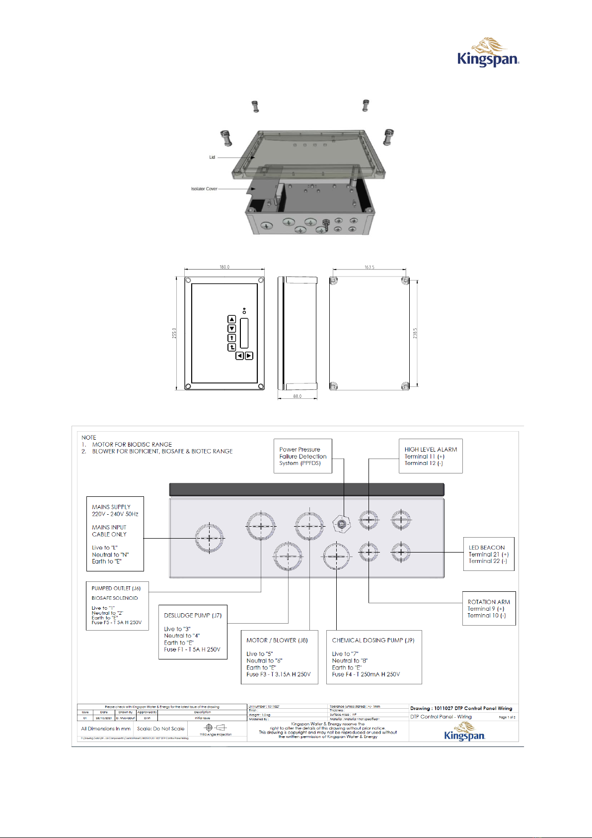
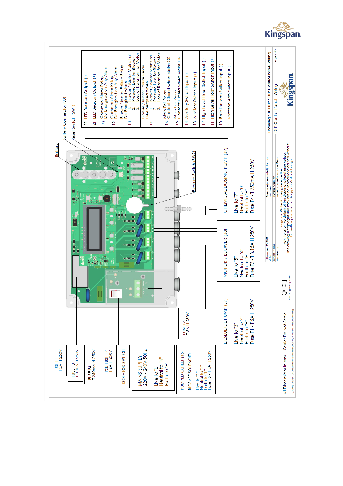
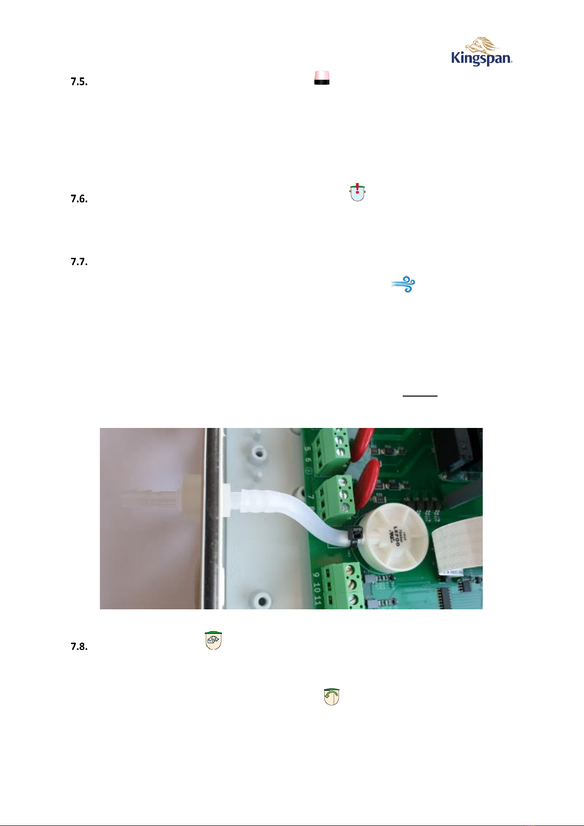
Installation of Integral Discharge Pump (where applicable)
Using a suitable M20 gland, feed the pump power cable through Gland Hole and terminate to connections 1 &
2 (J6) according to Figure 3 & Figure 4.
Installation of High-Level Alarm –HLA (where applicable)
Fix the black plastic bracket to the side wall of the baffle (the exact position is on the drawing included with
the HLA kit). Secure the float cable in the cable gland as shown on the drawing in the HLA kit. Pull the float
cable through any installed ducting into the blower housing. Complete wiring according to Figure 3 & Figure 4.