Kingwo MT36 User manual

+-++
MT36
User manual

1
Declaration
The contents of this manual might be updated without prior notice; the
updated content will be added to the new version of this manual.
Kingwo IoT reserve the rights to update the products or procedures
described in the manual at any time. If there is a description of the
product in the manual that does not match the actual product, the
actual product shall prevail. Kingwo owns the final interpretation rights
of this manual.

2
Contents
1. Product features ................................................... 4
2. Technical Specification .............................................. 5
3. Functions ......................................................... 6
3.1 Basic Functions ................................................ 6
3.1.1 Location monitoring ...................................... 6
3.1.2 Time monitoring ......................................... 7
3.1.3 Blind spot compensation ...................................7
3.1.4 Curve compensation ...................................... 7
3.1.5 Base station positioning ................................... 7
3.1.6 Main power detection .....................................7
3.1.7 Speeding alarm .......................................... 7
3.1.8 Main power failure alarm .................................. 8
3.1.9 Built-in battery .......................................... 8
3.1.10 Fast charge ............................................ 8
3.1.11 Power saving function ....................................8
3.1.12 Intelligent self-check ..................................... 8
3.1.13 Remote setting ......................................... 9
3.1.14 Remote upgrade (FOTA) .................................. 9
3.1.15 Multi-link .............................................. 9
3.2 Extened funtions .............................................. 9
3.2.1 Tire pressure detection .................................... 9
3.2.2 State detection ......................................... 10
3.2.3 Output control ..........................................10
3.2.4 ADDetect .............................................. 10
4.Installation guide .................................................. 11
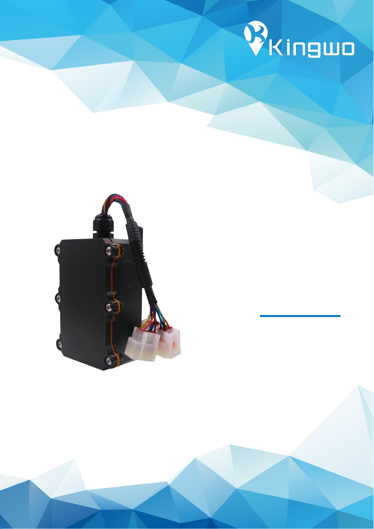
4.1 Wiring diagram ...............................................11
4.1.1 Open cover installation SIM card ........................... 11
4.1.2 Harness definition and wiring .............................. 12
4.2 Parameter settings ............................................ 11
4.2.1 Set up IP port ...........................................11
4.2.2 Set the return interval ....................................13
4.3 Installation location ........................................... 14

3
●MT36 is a special positioning product
●Can switch between wired and wireless
●Built-in 5200mAh polymer lithium battery, real-time positioning is used when
wiring.
●Support satellite positioning, AGPS positioning, base station positioning, etc.
●Communication support: GSM and GPRS.
●Expansion interface, can access tire pressure sensor,temperature sensor, load
sensor, door sensor, pressure switch, etc.
●Support remote firmware upgrade.
●Support multiple protocols, compatible with multiple standard platforms.
●IP68 highest waterproof.
PART 01
Product Overview

4
2.1 Main parameter
Product features
Description
Working voltage
DC 9V~36V,Suitable for 12V/24V vehicles
Working current
Average current<100mA@12V
Main power sleep
current
<15mA@12V
Battery sleep
current
Inside battery
Polymer lithium,3.7V/5200mAH
Charge
Inside battery support fast charge
Communication
Type
2G:GSM/GPRS 850/900/1800/1900MHz
Location type
Support Beidou/GPS dual-mode positioning, AGPS
assisted positioning and LBS positioning
Built-in antenna
Built-in GSM antenna and positioning antenna
Data storage
4MB FLASH(Optional)
I/O interface
2 input,1output
AD interface
2 ADC input,input voltage 0~5V
UART interface
2 RS232&1 RS485
Remote upgrade
Support remote FOTA upgrade firmware
Wake up
Timed wake up, open box alarm wake up
Open box alarm
Support unpacking wake-up alarm
Dual link
Support multi-IP multi-link simultaneous connection
Size
120mm*70mm*50mm
Temperature range
Working temperature:-25℃~70℃;
Storage temperature:-40℃~+85℃;
Protection level
IP68
PART 02
Technical Specification

5
2.2 Product configuration
Basic configuration
Item
Description
Main device
1pcs
3P cable
1pcs
Users manual
1pcs
Warranty card
1pcs
Qualified card
1pcs
Optional accessories
Door sensor
Tire pressure sensor
Temperature sensor
Humidity sensor
3.1 Basic Functions
3.1.1 Location monitoring
Including timing return, blind zone compensation, speed and mileage statistics,
area monitoring and other functions,The system issues positioning instructions, and
the terminal returns data including longitude, latitude, speed, direction, and status
information.
PART 03
Functions

6
3.1.2 Time monitoring
The vehicle GPS terminal can be set to upload the position and status information of
the vehicle to the backend at a certain time or a certain period or at a certain time
interval.
3.1.3 Blind spot compensation
When the terminal enters the GPRS blind zone, the track data will be saved at the
shortest 15S interval, and the blind zone data will be uploaded to the backend when
the GPRS is back online. The blind zone compensation data can be saved up to 4000.
3.1.4 Cornering Compensation
When the vehicle enters the curve lane, the terminal detects that the driving
direction has a certain angular deviation (default 20 degrees), and a timing feedback
message is added to ensure that the driving track is more accurate.
3.1.5 LBS
The terminal uses GPS positioning by default. When the GPS enters the blind zone
and cannot be accurately located, the terminal automatically switches to the base
station location. The terminal acquires the base station information every 30S and
uploads the base station information, the server interprets the specific location.
3.1.6 Main power detection
The terminal detects the main power voltage in real time. When the battery voltage
on the vehicle is too low, the vehicle terminal reports a low voltage alarm to the
monitoring center.
3.1.7 Over speed alarm
When the vehicle speed is higher than the over speed alarm value, the
vehicle-mounted terminal will notify the monitoring center.

7
3.1.8 Main power failure alarm
When the main battery of the vehicle is damaged or cannot supply power, the
built-in backup power supply can keep the system working and send a power failure
alarm to the monitoring center.
3.1.9 Built-in battery
The terminal has a built-in large-capacity high-temperature lithium battery, which
can detect the battery power in real time and report the battery power in real time.
When the built-in battery is working, the terminal has a variety of working states,
which can support the terminal to work continuously for no less than 7 days.
3.1.10 Fast charge
The terminal has a fast charging function. When the main power has power, the
built-in battery can be quickly charged through the fast charging module.
3.1.11 Power saving function
The terminal has a built-in G-Sensor, which can automatically detect the current
state of the device and distinguish between sports mode and static mode; when the
terminal is in static mode for a period of time, the terminal can automatically enter
the power saving mode, and the uploaded data will be converted to heartbeat
feedback; After the G-Sensor detects that it enters the sports mode in real time, the
terminal immediately exits the power saving mode and enters the normal working
state.
3.1.12 Intelligent self-check
The vehicle-mounted terminal can perform self-diagnosis. Once a fault occurs, it will
send a fault notification to the center, such as GPS, GSM, etc., and can automatically
take relevant measures. The monitoring center can also query the terminal's current
model, version, configuration, operating status, and equipment functions.

8
3.1.13 Remote setting
Remotely set various parameters of the terminal through the central system,
including IP, central number, various monitoring parameters, etc.
3.1.14 Remote Upgrade (FOTA)
As long as the GPRS status of the terminal is available, it can use remote wireless
mode to complete the terminal firmware upgrade.
3.1.15 Multi-link
The terminal supports dual IP dual link connection of the main server and the backup
server. The main server and backup server can be set in two ways: IP or domain
name.
3.2 Extended Functions
3.2.1 Tire pressure test
The terminal can be connected with a tire pressure detector to detect tire pressure
information in real time and send it to the background. The terminal can judge the

9
tire pressure status in real time, and once an abnormal tire pressure is found, it can
notify the tire pressure alarm in real time.
3.2.2 Status detection
The terminal supports 2 I/O detections, one high-level input and one low-level input,
which can be used to detect vehicle status. Such as opening the door, loading the
container, and hooking the front of the car.
3.2.3 Output control
The terminal supports 1 I/O output, low-level output, which can be used to connect
a controller.
3.2.4 AD detection
The terminal supports 2 channels of AD signal input, the voltage range is 0~5V, and
can be used for 2 channels of analog detection.

10
4.1 Wiring diagram
PART 04
Installation guide
Upload cover
Remove the face cover, use
screwdriver remove 6 screws.
Host fixing hole
SIM slot
Battery switch
Red LED,GPRS status
Green LED,GPS status
Insert SIM card into SIM slot
when device power is off.
Inner antenna

11
4.1.1 Open the cover and install the SIM card
Indication of LED lights:
Red GPRS LED light: Fast flashing, GPRS network connecting.
Flashes slowly every 5 seconds,GPRS connected.
Green GPS LED light: Fast flashing, GPS positioning.
Flash solid,GPS located.
No flashing,no GPS positioning.
4.1.2 Wire harness definition and wiring
The device uses car-grade waterproof connector (DJ70xxY) and corrugated pipe
protective sleeve as defaulted. Effectively protect the wiring harness and ensure the
stability of the link.
Equipment wiring instructions:
3P power plug: including power supply positive and negative wiring harness, when
installing the wiring, butt with the trailer power line.
4P communication plug: The default is RS232 serial communication interface,
providing 5V power output, which can supply power for external sensors. It can be
used to connect peripherals such as tire pressure sensors, humidity sensors, and
temperature sensors.
Note: This interface is a multiplexed communication port, which can extend up to 2
RS232/1 485 communications.
6P I/O port plug: Provides 2 AD input signal lines, 2 I/O input signal lines and 1 I/O
output signal line. It can be used to collect analog signals, connect to external
controllers and collect switch signals.

12
4.2 Parameter setting
4.2.1 Set IP port
Note: The terminal has a built-in ID number, and the client's IP port can be preset
before delivery. Generally, no parameter setting is required. If you need to modify
the IP, follow the instructions below. The following two methods require the SIM
card to activate the SMS function.
For example, the client's server IP is: 119.23.233.52, and the port number: 6000.
1For TCP connection, use SMS to write: *88*1119023233052*6000*1#, send it to
the local phone number, the terminal will reply: set ok, then the setting is successful.
2For UDP connection, write: *88*1119023233052*6000*0#, send it to the local
phone number, the terminal will reply: set ok, then the setting is successful.
After completing the above settings, the terminal can be connected to the server.
Indicator light is always on or flashing in green, and the red light is flashing
slowly,means terminal has been online and located normally. At this time, close the
top cover and tighten the screws,then fix the equipment on the trailer for use.
3P power plug Red:Positive
Black:Negative
4P communication plug Green+blue:Serial communication signal line
Black:Signal ground
Orange:5V Power supply
6P I/Oplug Brown/Blue:2 AD input signal lines
Yellow:I/O output signal line
Purple/Orange:2 I/O input signal line

13
4.2.2 Set the return interval
Instruction format: HC, T1, T2, T3#
Instructions:
T1: Start the return interval, the value range is 5-1800 seconds, the default is 30
seconds
T2: Turn off the return interval, the value range is 5-1800 seconds, the default is 120
seconds
T3: Sleep return interval, the value range is 15-21600 seconds, the default is 180
seconds
Example: HC,60,180,300# Set T1/T2/T3 to 60 seconds, 180 seconds, 300 seconds
respectively
Use note:
It is strictly forbidden to use the equipment in violation of the operating instructions,
disassemble it without permission, collide, charge, soak in water, exceed 80°C,
man-made failure, force majeure damage, etc., otherwise it may cause short circuit,
insufficient working time, battery deformation, leakage, explosion, etc. No warranty
or compensation will be made for joint losses.
4.3 Installation location
MT36 is designed to meet the IP68 protection standard and can be installed and
fixed in exposed environments. Normally, it can be fixed at the position identified in
the figure below, and the equipment line is routed along the original car harness.

14
Place 1
Place 2
Place 3
HC,<T1>,<T2>,<T3>#
Set the upload interval in real time tracking mode:
T1: upload interval in ignition on status, range,5-30s ,default 90s
T2: Upload interval in ignition off status
,range 5-600 s, default 120 s
T3:Sleep return interval, range 10-1800 s, default 180
For example:
HC,30,90# Set the upload interval as 30s and 90s in ignition on
HC,30,90,300# Set the upload interval as 30s, 90 s in ignition off
and 300s while in sleep mode
UTC,TTTT#
Set time zone,unit minutes, default UTC+8:00
For example:
UTC,480# Time zone UTC+8:00
UTC,330# Time zone UTC+5:30
UTC,-480# Time zone UTC-8:00
UTC,-210# Time zone UTC-3:30

15
WY,<A>[,R,M]#
Set towing alarm:
A: On and off,1:On 0:Off
Default is off
R: Towing radius,Default 500 meters,Range:100-2000 meters
M: Alarm mode,Optional
M=0:GPRS,M=1:SMS+GPRS
Eg:WY,1,100,1# towing alarm on,radius 100 meters
notification mode:GPRS+SMS
LOCKACCOFF,A#
Set vehicle lock
A=0 Receive lock command, execute immediately
A=1 Receive lock command, if ACC is off, execute immediately, if
ACC is on, store this command until ACC off
A=2 Store the command, lock vehicle from ACC Off to On, if the
communication is well, lock vehicle, otherwise wait for next turn
For example:LOCKACCOFF,0# means execute the lock command
immediately after receiving it
APN,apn,user,pswd#
Set APN, User name and password
For example:APN,CMNET,internet,internet#
APN:CMNET
Username: internet
Password: internet
*22*1#
Restore to factory setting
*22*2#
Lock vehicle
*22*3#
Unlock vehicle
*22*4#
Reboot device
IP,ip or dns,port,type#
IP,119.23.233.52,6000,1#
Set the primary server IP:119.23.233.52,port 6000,communication
type:TCP
IP,www.365qczx.com,6000,0#
Set the primary server domain:www.365qczx.com,Port 6000,
communication type UDP

16
Shenzhen Kingwo IoT Co., Ltd
Contact us
+86 0755 86704262
marketing@kingwoiot.com
www.itracksense.com www.kingwoiot.com
Room 301-302, 3rd Floor, Comprehensive Building,
Tsinghua Information Hi-tech Park, North Science Park,
Nanshan District, Shenzhen ,China 518052
Table of contents
Other Kingwo GPS manuals