7
INSTALLATION
INSTALLATION
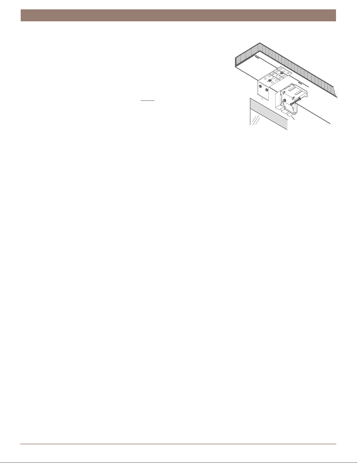
Mount the Installation Brackets — Outside Mount with Valance
With the optional valance, first the valance headboard is mounted and then the installation brackets are mounted to the wall or
molding under the headboard.
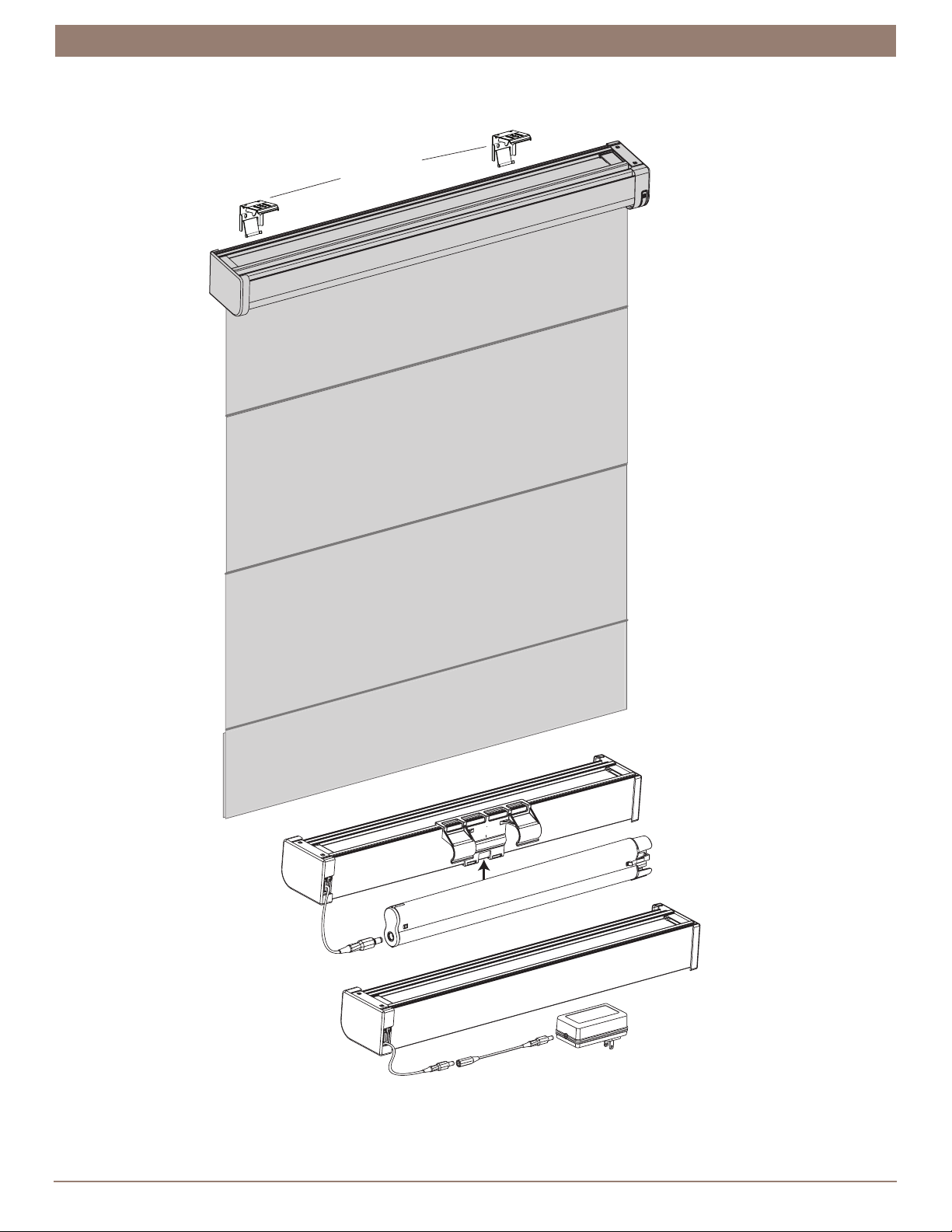
The standard shade has an attached battery wand requiring a spacer block to be used with the installation bracket. DC power
supply or satellite battery pack will not require a spacer block.
■ Mark where the ends of the valance headboard will be located. Center the headboard above the window opening at the height
to allow enough room for the shade to be mounted below. Use a pencil to lightly mark where its ends are located.
➤ Alternatively, measure the width of the valance headboard and use this measurement to determine where the ends of the
headboard will be located.
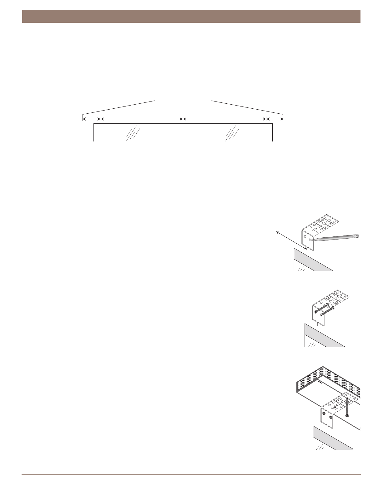
➤ Mark L-bracket locations. Use a pencil to lightly mark 3” in from each valance headboard end location. If more than two
L-brackets came with your order, make additional marks to space the other bracket(s) evenly between the two end brackets.
With two-piece headboards (valances over 96” wide), the two equal-width sections abut in the center. Space brackets 3” in
from the ends of each section and evenly in-between.
IMPORTANT: Be sure to place a bracket on each side of the center split.
■ Mark screw locations. Center an L-bracket on each mark. Then mark where to drill
the screw holes for the mounting screws.
➤ The top of the L-brackets should be 1” below the height where you want the
top of the valance to be located.
➤ The rear of the L-brackets must be flush against a flat mounting surface. Do not
mount L-brackets on curved molding.
IMPORTANT: The tops of the L-brackets must align level aer mounting.
■ Drill 1∕8” pilot holes for the L-bracket mounting screws.
➤ Mount into wood whenever possible.
CAUTION: Use drywall anchors when mounting into drywall. Drywall anchors are not provided.
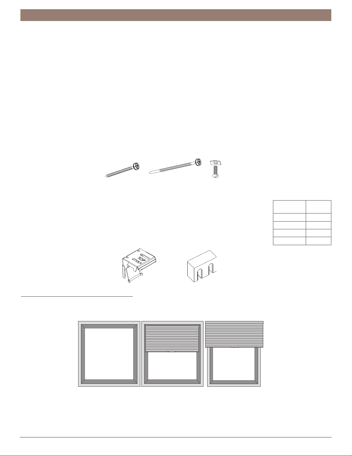
■ Attach the L-brackets to the mounting surface. Use the 1½” hex head screws provided with your order.
■ Check alignment. The tops of all L-brackets must be aligned and level.
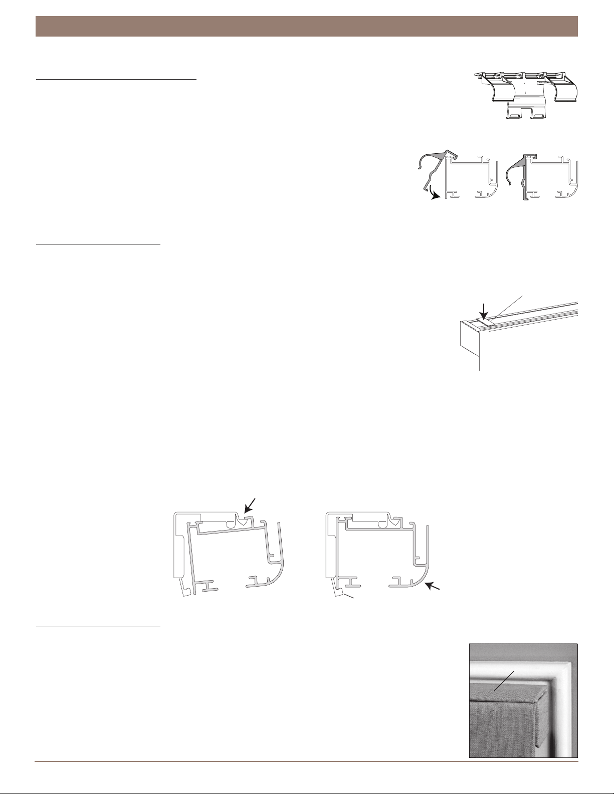
■ Mark screw locations for attaching the valance headboard. Position the valance headboard on top of
the L-brackets with its ends aligned with the end marks and the back against the wall.
➤ The hook-and-loop material faces front and the staples on the headboard face down.
➤ Mark the bottom of the headboard (the side with the staples) through the front and rear slotted
holes on the center of the L-brackets.
■ Drill 1∕8” pilot holes for the valance headboard mounting screws. Remove the headboard and drill the
pilot holes. Be careful not to drill through the fabric on the top of the valance headboard.
■ Attach the headboard to the L-brackets. Use the provided ¾” hex head screws. (Longer screws will
pierce the top of the fabric.)
3" 3"
Space EvenlySpace Evenly
Valance Headboard End Marks
Window Opening
Valance
L-Bracket
3"
Valance
Headboard
End Mark
Valance
L-Bracket
3"
Valance
Headboard
End Mark
1½" Hex Head
Screws