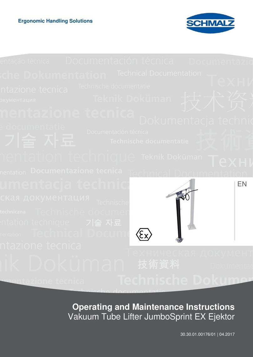
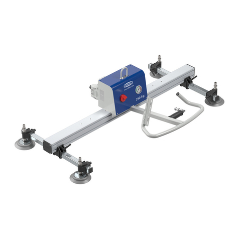
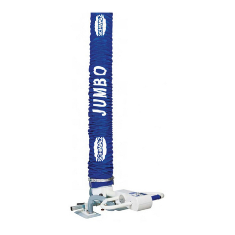
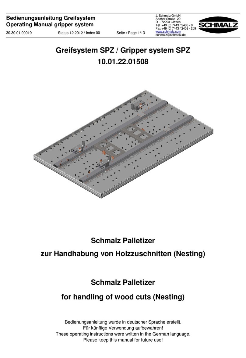
Schmalz JumboFlex Safety+ User manual

JumboFlex Safety+
Operating Instructions
WWW.SCHMALZ.COM EN-US · 30.30.01.02553 · 00 · 09/20

Note
The Operating instructions were originally written in German. Store in a safe place for future reference.
Subject to technical changes without notice. No responsibility is taken for printing or other types of er-
rors.
Published by
© J.SchmalzGmbH, 09/20
This document is protected by copyright. J.SchmalzGmbH retains the rights established thereby. Repro-
duction of the contents, in full or in part, is only permitted within the limits of the legal provisions of
copyright law. Any modifications to or abridgments of the document are prohibited without explicit writ-
ten agreement from J.SchmalzGmbH.
Contact
J. Schmalz GmbH
Johannes-Schmalz-Str. 1
72293 Glatten, Germany
T: +49 7443 2403-0
www.schmalz.com
Contact information for Schmalz companies and trade partners worldwide can be found at:
www.schmalz.com/salesnetwork
2 / 52 EN-US · 30.30.01.02553 · 00 · 09/20

Contents
EN-US · 30.30.01.02553 · 00 · 09/20 3 / 52
Contents
1 Important Information ...................................................................................................................................6
1.1 The technical documentation is part of the product ........................................................................ 6
1.2 Note on Using these Operating Instructions ..................................................................................... 6
1.3 Warnings in This Document................................................................................................................ 6
1.4 Symbol.................................................................................................................................................. 6
1.5 Information Signs on the Lifting Device ............................................................................................ 7
1.6 Type Plate ............................................................................................................................................ 8
2 Fundamental Safety Instructions...................................................................................................................9
2.1 Intended Use........................................................................................................................................ 9
2.2 Non-Intended Use ............................................................................................................................... 9
2.3 Danger Zone ........................................................................................................................................ 9
2.4 Hazards during Operation ................................................................................................................ 10
2.5 Environmental and Operating Conditions....................................................................................... 11
2.6 Workplace Requirements.................................................................................................................. 11
2.7 Personnel Qualifications ................................................................................................................... 11
2.8 Personal Protective Equipment ........................................................................................................ 12
2.9 Safety Features .................................................................................................................................. 12
2.10 Technical Condition........................................................................................................................... 12
2.11 Operator Responsibility .................................................................................................................... 12
2.12 Country-Specific Regulations for the Operator............................................................................... 12
3 Product Description ......................................................................................................................................13
3.1 Mode of Operation ........................................................................................................................... 13
3.2 Components....................................................................................................................................... 13
3.3 Vacuum Pump.................................................................................................................................... 13
3.4 Operator Handle ............................................................................................................................... 14
3.5 Radio Remote Control (Optional) .................................................................................................... 14
3.6 Motor-Protection Switch................................................................................................................... 14
3.7 Gripper Types..................................................................................................................................... 14
3.7.1 Suction Cups...............................................................................................................................15
3.7.2 Mechanical Grippers.................................................................................................................. 16
3.8 Rotary Union...................................................................................................................................... 18
3.9 Vacuum Supply .................................................................................................................................. 18
3.10 Protective Tube.................................................................................................................................. 18
3.11 Options............................................................................................................................................... 18
3.11.1 Dust Filter (Option)....................................................................................................................18
3.11.2 Silencer Box (option) ................................................................................................................. 19
3.11.3 Blower Console (Option)........................................................................................................... 19
3.11.4 Retaining Net (Option)..............................................................................................................19
3.11.5 Parking System for the Gripper (Optional) .............................................................................. 19
4 Technical Data ...............................................................................................................................................21
4.1 Tube Lifters ........................................................................................................................................ 21
4.2 Radio Remote Control....................................................................................................................... 21
5 Transport and Storage..................................................................................................................................23
5.1 Protective Equipment........................................................................................................................ 23

Contents
4 / 52 EN-US · 30.30.01.02553 · 00 · 09/20
5.2 Checking the Delivery ....................................................................................................................... 23
5.3 Removing the Packaging .................................................................................................................. 23
5.4 Transporting the Tube Lifter ............................................................................................................ 23
5.5 Storing the Tube Lifter...................................................................................................................... 24
6 Installation.....................................................................................................................................................25
6.1 Safety ................................................................................................................................................. 25
6.1.1 Protective Equipment................................................................................................................ 25
6.1.2 Safety Instructions for Maintenance ........................................................................................ 25
6.2 Mounting the Vacuum Supply Hose ................................................................................................ 25
6.3 Replacing the Suction Cup................................................................................................................ 26
6.3.1 Removing the Suction Cup........................................................................................................26
6.3.2 Attaching the Suction Cup........................................................................................................ 27
6.4 Installing the Vacuum Pump............................................................................................................. 27
6.5 Checking the Rotation Field ............................................................................................................. 28
6.6 Shortening the Lift Tube................................................................................................................... 28
6.7 Adjusting the Hovering Position ...................................................................................................... 30
6.8 Adjusting the Lowering Speed ......................................................................................................... 31
6.9 Attaching the Quick Reference Guide ............................................................................................. 31
6.10 Installing the Radio Remote Control (Option) ................................................................................ 31
6.10.1 Installing the Receiver ............................................................................................................... 31
6.10.2 Registering the Transmitter ...................................................................................................... 32
6.10.3 Registering an Additional Transmitter.....................................................................................33
6.11 Installing the Silencer Box (Option) ................................................................................................. 33
6.12 Installing the Dust Filter (Option) .................................................................................................... 34
6.13 Installing and Adjusting the Vacuum Regulation Valve (Option).................................................. 34
6.14 Checks Before Start of Operations ................................................................................................... 34
7 Operation ......................................................................................................................................................35
7.1 Safety ................................................................................................................................................. 35
7.1.1 Protective Equipment................................................................................................................ 35
7.1.2 Personnel Qualifications ........................................................................................................... 35
7.1.3 Safety Instructions for Operation ............................................................................................. 35
7.1.4 Using the Tube Lifter Correctly.................................................................................................36
7.1.5 Safely Guiding the Lifted Load ................................................................................................. 37
7.1.6 What to Do in an Emergency....................................................................................................37
7.2 Replacing the Suction Cup................................................................................................................ 37
7.3 Switching on the Tube Lifter ............................................................................................................ 38
7.4 Setting the Hovering Position .......................................................................................................... 38
7.5 Adjusting the Lowering Speed ......................................................................................................... 38
7.6 Raising the Load ................................................................................................................................ 38
7.7 Vertically Apply Suction to the Load and Set It Down Horizontally .............................................. 40
7.8 Setting Down the Load ..................................................................................................................... 41
7.9 Rotating the Load ............................................................................................................................. 42
7.10 Parking the Tube Lifter ..................................................................................................................... 42
8 Troubleshooting............................................................................................................................................44
8.1 Safety ................................................................................................................................................. 44
8.1.1 Protective Equipment................................................................................................................ 44
8.1.2 Safety Instructions for Troubleshooting ..................................................................................44
8.2 Help with Malfunctions .................................................................................................................... 44

Contents
EN-US · 30.30.01.02553 · 00 · 09/20 5 / 52
9 Maintenance..................................................................................................................................................46
9.1 Safety ................................................................................................................................................. 46
9.1.1 Protective Equipment................................................................................................................ 46
9.1.2 Safety Instructions for Maintenance ........................................................................................ 46
9.2 Maintenance Schedule...................................................................................................................... 46
9.2.1 Safety Features .......................................................................................................................... 46
9.2.2 Condition and Function of the Tube Lifter.............................................................................. 47
9.3 Regular Inspections ........................................................................................................................... 48
9.4 Inspecting Safety Features ................................................................................................................ 48
9.4.1 Checking the Non-Return Valve of the Rotary Union............................................................. 48
9.5 Vacuum blower ................................................................................................................................. 49
9.6 Cleaning the Tube Lifter ................................................................................................................... 49
9.7 Dust Filter in the Vacuum Pump....................................................................................................... 49
9.8 Checking the Level of Wear on the Rotary Union .......................................................................... 49
10 Decommissioning and Recycling..................................................................................................................51
10.1 Safety ................................................................................................................................................. 51
10.2 Taking the Tube Lifter out of Operation......................................................................................... 51
10.3 Disposing of the Tube Lifter ............................................................................................................. 51

Important Information
6 / 52 EN-US · 30.30.01.02553 · 00 · 09/20
1Important Information
1.1The technical documentation is part of the product
1. For problem-free and safe operation, follow the instructions in the documents.
2. Keep the technical documentation in close proximity to the product. The documentation must be ac-
cessible to personnel at all times.
3. Pass on the technical documentation to subsequent users.
ðFailure to follow the instructions in these Operating instructions may result in life-threatening in-
juries!
ðSchmalz is not liable for damage or malfunctions that result from failure to heed these instructions.
If you still have questions after reading the technical documentation, contact Schmalz Service at:
www.schmalz.com/services
1.2Note on Using these Operating Instructions
The product JumboFlex is generally referred to as the tube lifter.
J.SchmalzGmbH is generally referred to as Schmalz in these operating instructions.
These Operating Instructions contain important notes and information about the different operating
phases of the product:
• Transport, storage, start of operations and decommissioning
• Safe operation, required maintenance, rectification of any faults
The operating instructions describe the product at the time of delivery by Schmalz.
The tube lifter can be operated with various suction cups and mechanical grippers. For special
grippers, refer to the operating instructions in the appendix.
1.3Warnings in This Document
Warnings warn against hazards that may occur when handling the product. The signal word indicates the
level of danger.
Signal word Meaning
DANGER Indicates a high-risk hazard that will result in death or serious injury if not
avoided.
WARNING Indicates a medium-risk hazard that could result in death or serious injury if
not avoided.
CAUTION Indicates a low-risk hazard that could result in minor or moderate injury if
not avoided.
NOTE Indicates a danger that leads to property damage.
1.4Symbol
This symbol indicates useful and important information.
üThis symbol represents a prerequisite that must be met prior to an operational step.
4This symbol represents an action to be performed.
ðThis symbol represents the result of an action.
Actions that consist of more than one step are numbered:

Important Information
EN-US · 30.30.01.02553 · 00 · 09/20 7 / 52
1. First action to be performed.
2. Second action to be performed.
1.5Information Signs on the Lifting Device
Next accident prevention inspec-
tion (valid for Germany)
27.03.01.00053
Date and time for the accident
prevention inspection
27.03.01.00055
Permissible lift capacity
xxx kg
Lift
capacity
Ensure that the Permissible lift
capacity sticker is clearly legible
at all times.
Quick guide
27.03.01.00623
Read the instructions
27.03.01.00291

Important Information
8 / 52 EN-US · 30.30.01.02553 · 00 · 09/20
Lowering speed label
11.01.43.00480
Release the load label
11.01.43.00481
1.6Type Plate
The type plate is permanently attached to the product and must always be clearly legible.
For each product, the type plate contains the following data:
• Abbreviated device designation
• Order number
• Serial number or SNR
• Year of manufacture
• Max. permitted lift capacity
• Weight
• Electrical voltage
4Please specify all the information above when ordering replacement parts, making warranty claims
or for any other inquiries.

Fundamental Safety Instructions
EN-US · 30.30.01.02553 · 00 · 09/20 9 / 52
2Fundamental Safety Instructions
2.1Intended Use
The tube lifter Jumbo is designed solely for lifting and transporting loads in conjunction with a crane sys-
tem.
Two-hand operation for suction cup: After depositing the load, it can only be released from
the suction cup if the operator deliberately actuates two operating elements.
The tube lifter is intended solely for commercial use indoors. The order confirmation describes the specific
use of the tube lifter JumboFlex. All other types of use are considered non-intended use.
The tube lifter is built in accordance with the latest standards of technology and is shipped in safe condi-
tion. However, hazards can arise during use.
Before handling unfamiliar loads, ensure that the loads to be lifted are rigid enough that they are not
damaged during handling. Perform tests to do so where necessary.
The tube lifter must be used only when hung from the rotary union suspension eye. Observe the type
plate and lift capacity sticker.
2.2Non-Intended Use
Schmalz accepts no liability for damages caused by the use of the tube lifter for purposes other than
those described under “Intended Use”. The use of the tube lifter for loads that are not specified in the or-
der confirmation or have different physical properties than those specified in the order confirmation shall
be considered non-intended use.
In particular, the following are considered non-intended use:
• In potentially explosive atmospheres
• Over 1600m above sea level (the required minimum vacuum cannot be achieved).
• Using as a climbing aid
• Lifting people or animals
• Storing loads while picked up
• Supporting the lifting process by applying external forces
• Applying suction to building components, equipment or supporting surfaces.
• Applying suction to bulk materials (e.g. granulates)
• Applying suction to liquids.
• Evacuation of objects that are in danger of imploding
• Freeing building components or immovable equipment
2.3Danger Zone
Persons in the working area of the tube lifter Jumbo may suffer life-threatening injuries.

Fundamental Safety Instructions
10 / 52 EN-US · 30.30.01.02553 · 00 · 09/20
Danger Zone
The danger zone of the tube lifter includes the following areas:
• The area directly above and below the gripper or above and below the load
• The area immediately around the tube lifter and load
• The working area of the crane system
Measures for avoiding accidents:
• Ensure that no persons are present in the danger zone.
• Ensure that collisions with the surrounding environment and objects do not occur to prevent the
load from breaking off.
2.4Hazards during Operation
CAUTION
Shearing off of the load due to collision with surrounding objects
Risk of injury!
4Ensure that no obstacles or interference contours are present within the working zone
during handling.
CAUTION
Risk of injury due to exposed suction points
4Do not place eyes, ears or hands into suction points.
4Do not bring exposed suction points close to eyes or body orifices.
4Do not place suction plates on the human body.
NOTE
Damage to vacuum hoses due to sharp objects
4Ensure that vacuum hoses cannot be damaged by sharp objects.

Fundamental Safety Instructions
EN-US · 30.30.01.02553 · 00 · 09/20 11 / 52
2.5Environmental and Operating Conditions
CAUTION
Dangerous gases, vapors or dusts are sucked in and dispersed by the vacuum gen-
erator.
Difficulty breathing.
4Before commencing work, ensure that the ambient air does not contain any hazardous
substances.
4Make sure that there are no hazardous substances on the load that can be sucked in.
4If the ambient air is dusty, use a dust filter (particle size max. 5µm).
The tube lifter Jumbo must be operated only under the following conditions:
• Temperature range from 0°C to +40°C.
• The environment must be free from humidity, moisture, dirt, dust, oil or other climatic conditions
that may reduce friction levels.
• The tube lifter Jumbo must have the necessary specifications for the relevant load.
4If in doubt, consult Schmalz before the start of operations.
2.6Workplace Requirements
The following requirements must be fulfilled to ensure a safe workplace:
• The operating company is obligated to perform a risk assessment for the environmental conditions
at the installation location.
• The type plate and warning signs must be legible.
• The operator must have a clear view of the whole working area, the workplace must be adequately
lit and free of glare, and the area around the workplace must be clean and clear.
2.7Personnel Qualifications
Unqualified personnel cannot recognize dangers and are therefore exposed to higher risks!
The operating company must ensure the following points:
• The personnel must be commissioned for the activities described in these operating instructions.
• The staff must be at least 18 years of age and physically and mentally capable.
• The product must be operated only by persons who have undergone appropriate training.
• Personnel must receive regular safety briefings (frequency as per country-specific regulations).
• Work on electrical equipment must be carried out only by qualified electrical specialists.
• Installation, maintenance, and repairs must be carried out only by specialists from J.SchmalzGmbH
or by persons who can prove that they have undergone appropriate training at Schmalz.
The following target groups are addressed in these operating instructions:
• Persons trained in operating and cleaning the product.
• Mechanical and electrical specialists who are responsible for installing, troubleshooting and main-
taining the product.
The company operating the crane system must comply with country-specific regulations regarding the
age, ability and training of the personnel.
Valid for Germany:
A qualified employee is defined as an employee who has received technical training and has the knowl-
edge and experience – including knowledge of applicable regulations – necessary to enable him or her to
recognize possible dangers and implement the appropriate safety measures while performing tasks. Qual-
ified personnel must observe the pertinent industry-specific rules and regulations.

Fundamental Safety Instructions
12 / 52 EN-US · 30.30.01.02553 · 00 · 09/20
2.8Personal Protective Equipment
To avoid injury, always use appropriate protective equipment that is suitable for the situation. The protec-
tive equipment must meet the following standards:
• Protective work shoes in safety class S1 or higher
• Sturdy work gloves in safety category 2133 or higher
• Industrial helmet
• Ear protection class L or higher
• Eye protection class F
• Hair net
• Closely fitting clothing
2.9Safety Features
The tube lifter Jumbo has the following safety features:
• The non-return valve in the rotary union causes the tube lifter to be lowered slowly when the vac-
uum supply fails.
• The load can only be released via two-hand operation.
1. Before each start of operations, ensure that the safety features are in perfect condition.
2. Safety features must not be disabled under any circumstances.
2.10Technical Condition
Safety and functionality are impaired if the product is operated in defective condition.
1. The product must only be operated when in perfect technical working order – i.e., in its original con-
dition.
2. Follow the maintenance schedule.
3. Only use original spare parts.
4. If the operating behavior should change, check the product for faults. Rectify faults immediately.
5. Unauthorized conversion or modification of the product is prohibited.
6. Under no circumstances must safety features be disabled.
Schmalz assumes no liability for consequences of modifications over which it has no control.
2.11Operator Responsibility
The operator is also responsible for third parties in the working area of the tube lifter. The operating
company must ensure that they have the appropriate qualifications and skills.
1. Ensure that the tube lifter cannot be used during maintenance or repair work.
2. The responsibilities for the various activities performed on the tube lifter must be clearly defined.
3. Ensure that these responsibilities are adhered to.
4. When handling unfamiliar loads, carry out tests where necessary to ensure safe operation:
ðThe load is sufficiently rigid that it cannot be damaged during handling.
2.12Country-Specific Regulations for the Operator
1. Observe the country-specific regulations regarding accident prevention, safety testing and environ-
mental protection.
2. Only use the tube lifter once you have verified that the crane system employed complies with the
country-specific rules and safety regulations.

Product Description
EN-US · 30.30.01.02553 · 00 · 09/20 13 / 52
3Product Description
3.1Mode of Operation
The tube lifter is used for fast and frequent lifting and moving of loads (for the lift capacity, see the type
plate).
The vacuum generator generates the vacuum, which is then directed to the suction cups via the supply
hose, rotary union and lift tube.
The vacuum keeps the load attached to the suction cup. Controlled leakage of the vacuum in the lift tube
is used for lifting and lowering.
Two-hand operation for suction cup: After depositing the load, it can only be released from
the suction cup if the operator deliberately actuates two operating elements.
3.2Components
2
3
4
9
6
7
1
10
11
5
1 Vacuum pump 2 Suspension eye
3 Rotary Union 4 Lift Tube
5 Lifting unit 6 Operator handle
7 Suction cup 9 Motor-protection switch
10 Dust filter 11 Silencer box
For operation of the following components, see also the operating instructions in the appendix:
• Vacuum Pump
• Dust filter (option)
• Silencer box (option)
• Motor-protection switch
3.3Vacuum Pump
See the vacuum pump operating instructions in the appendix.

Product Description
14 / 52 EN-US · 30.30.01.02553 · 00 · 09/20
3.4Operator Handle
6.3
5.3
6.6
6.3
6.6
5.6
6.5
5.3 Adjustment screw for the hovering posi-
tion
5.6 Rotation unit latching bolt
6.3 Pushbutton UP/DOWN 6.5 Adjustment screw for the lowering speed
6.6 Control lever for releasing the load
3.5Radio Remote Control (Optional)
The radio remote control enables wireless activation and deactivation of the vacuum generator.
6.1 6.4
6.1 Vacuum generator ON/OFF (transmitter) 6.4 Receiver
3.6Motor-Protection Switch
The motor-protection switch is used to switch the electrical vacuum generation on and off and provide
overvoltage protection. It can be integrated into the Schmalz crane column without the need for compli-
cated wiring and can be optionally locked.
See the motor-protection switch operating instructions in the appendix.
3.7Gripper Types
The tube lifter JumboFlex can be operated with various grippers. The grippers must be approved for use
with this tube lifter.
The displayed figures are only examples. Depending on the particular design, they can differ from the
product.
For special grippers, refer to the operating instructions in the appendix.

Product Description
EN-US · 30.30.01.02553 · 00 · 09/20 15 / 52
4If in doubt, consult Schmalz Service before the start of operations.
3.7.1Suction Cups
Gripper type Image Application area
Round vacuum
gripper
Barrels, buckets, stone slabs
with rough surfaces
Double suction
cup
Clamped, glued, strapped or
open cardboard boxes, also
for crates, sheets, etc.
Sack gripper Paper and plastic sacks, raw
rubber bails, shrink-wrapped
packages, etc.

Product Description
16 / 52 EN-US · 30.30.01.02553 · 00 · 09/20
Gripper type Image Application area
Multiple vacuum
gripper
Cardboard boxes
Multi-gripper Cardboard boxes with vari-
ous sizes and properties;
leakage compensation with
minimum coverage of 75%
Four-head suction
cup
Cardboard boxes, sheets and
non-rigid parts
3.7.2Mechanical Grippers
The venting lever (6.6) for releasing the load does not affect the use of mechanical grippers.

Product Description
EN-US · 30.30.01.02553 · 00 · 09/20 17 / 52
Gripper type Image Application area
Sack gripper Gripping of sacks by clamp-
ing the top seam
Box gripper Gripping of semi-open front
storage containers on the
upper edge of the stack
Shaft gripper for
small load carriers
Gripping of specific small
load carriers (types C, R, RL,
and L) by reaching into the
shaft
For more information, see
the gripper operating in-
structions in the appendix.
Fork gripper for
small load carriers
Gripping of small load carri-
ers (type C) on the external
slot

Product Description
18 / 52 EN-US · 30.30.01.02553 · 00 · 09/20
Gripper type Image Application area
Suspension hook Gripping of various loads
with loops, lugs or handles
such as buckets, jugs, etc.
3.8Rotary Union
3
2
The tube lifter must be used only when hung from the suspension eye (2) of the rotary union (3).
The swivel bearing enables continuous rotation of the tube lifter.
3.9Vacuum Supply
The length of the supply hose is adapted to the individual application. Correct function of the tube lifter
Jumbo can only be ensured if the length of the supply hose does not exceed 50m.
3.10Protective Tube
The protective tube protects the lift tube against mechanical damage.
3.11Options
3.11.1Dust Filter (Option)
We strongly recommend that a dust filter be built into the vacuum line in order to protect the vacuum
generator from all types of contamination (ambient dust, dirty load, etc.).

Product Description
EN-US · 30.30.01.02553 · 00 · 09/20 19 / 52
NOTE
Intake of ambient dust or other foreign bodies
Damage to the vacuum generator!
4When working in dusty environments or handling dusty loads, a dust filter must be in-
stalled upstream of the vacuum generator.
ðIf no dust filter is installed, this will void the warranty for damage caused to the vac-
uum generator as a result of foreign bodies being sucked in.
See the dust filter operating instructions in the appendix.
3.11.2Silencer Box (option)
The silencer box reduces the noise level of the vacuum generator and protects it against contamination.
See the silencer box operating instructions in the appendix.
3.11.3Blower Console (Option)
The blower console allows the vacuum generator and silencer box to be attached to the crane column or
hall struts.
See the blower console operating instructions in the appendix.
3.11.4Retaining Net (Option)
The retaining net protects the suction cups and the lift tube when the tube lifter is not in use and allows
for space-saving storage.
3.11.5Parking System for the Gripper (Optional)
The parking system makes it possible to safely store grippers that are not needed. The parking system is
available in three different lengths for two to four grippers.
Parking system with multiple vacuum gripper
The parking system is compatible with all JumboFlex grippers with a size of 20, 35, and 50 (except box
grippers).
The parking system can be mounted horizontally or vertically on a wall, or vertically on a column. The
mounting kit is not included in delivery. It is the customer’s responsibility to check whether the properties
of the wall can accommodate the parking system.
Maximum gripper weight per mounting adapter: 5kg.
If required, the parking system can be supplemented with any number of mounting adapters. The maxi-
mum number of grippers in the parking system is determined by the size of the gripper.

Product Description
20 / 52 EN-US · 30.30.01.02553 · 00 · 09/20
4To attach a gripper, insert the four screw
heads of the connection plate into the holes
of the mounting adapter from the front.
Example of a single vacuum gripper
This manual suits for next models
3
Table of contents
Other Schmalz Lifting System manuals

Schmalz
Schmalz SPZ Series User manual

Schmalz
Schmalz VACUMASTER HHVM User manual

Schmalz
Schmalz VACUMASTER VHB 250 User manual

Schmalz
Schmalz Jumbo Ergo User manual

Schmalz
Schmalz VACUMASTER COIL User manual

Schmalz
Schmalz VacuMaster VM-BASIC User manual

Schmalz
Schmalz VACUMASTER BASIC User manual

Schmalz
Schmalz VACUMASTER 1000 User manual

Schmalz
Schmalz JumboPicker-Flex Manual

Schmalz
Schmalz Jumbo Flex 20 User manual