manuals.online logo
Brands
  1. Home
  2. •
  3. Brands
  4. •
  5. KKT chillers
  6. •
  7. Chiller
  8. •
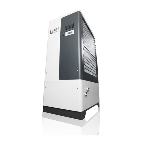
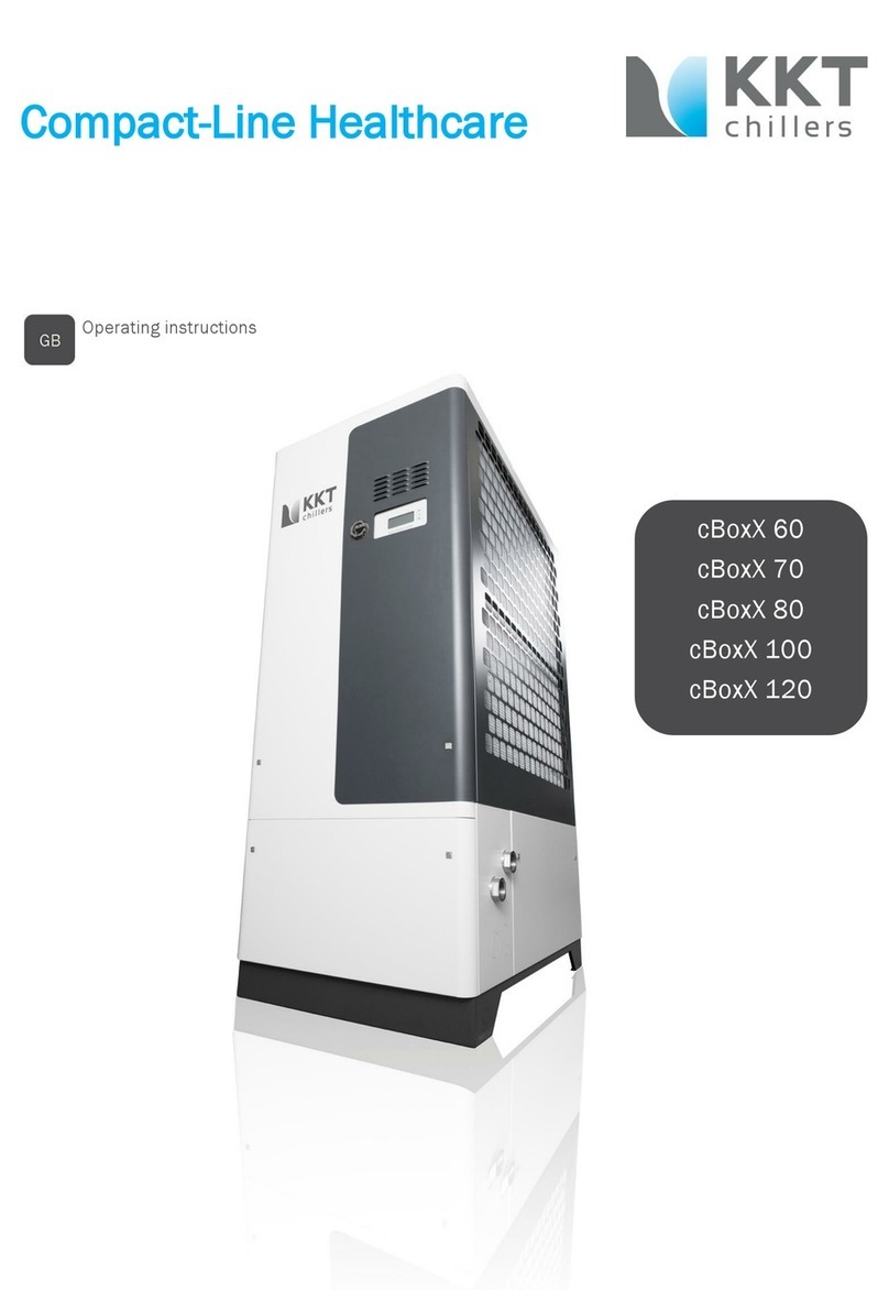
  9. KKT chillers cBoxX 100 Service manual

KKT chillers cBoxX 100 Service manual

Schutzvermerk nach DIN ISO 16016 beachten !
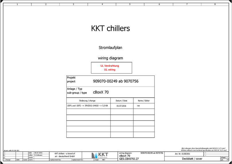
Deckblatt / cover
cBoxX 100
Zur Beachtung !
Der Schalt lan ist Bestandteil des Schaltschrankes gleicher Baunummer und
sollte nicht daraus entfernt werden, damit er im Notfall sofort verfügbar ist.
Bei unbefugten Eingriffen in die Verdrahtung erlischt unsere Gewährleistung !
The circuit diagram is an integral art of the switch cabinet, with matching build number.
should not be removed and should always be available on short notice in case of emergency.
Unauthorized changes to the wiring will void the Warranty!
note !
Vor Inbetriebnahme - alle Schrauben an Schützen,
Klemmen , Relais und Reglern
Tighten all screws on contactors,
clam s, relays and controls rior to commissioning.nachziehen.
Betriebss annung / Line:
Schutzart / Prot.class:
Steuers annung / Control voltage:
Anschlußleistung / Connected load:
max. Stromaufnahme / Max. current:
Vorsicherung / Main fuse:
: 460 V / 60Hz
: 24 V DC
: ca. 46,0 kW/ ca. 52,6 kVA
: ca. 66,0 A
: IP 54
: 80 A
SCCR:
max. Einschaltstrom / inrush am s:
: 20 kA
: 155 A Drahtfarben / colors of wiring :
sheet
sh.
1
23
3 4 5 6 7
KKT chillers - a brand of cBoxX
ait-deutschland GmbH
Art. Nr. 61525501
Hau tstromkreise / main ower : schwarz / black
Schutzleiter / rotective conductor : grün-gelb / green-yellow
Steuers annung / control voltage 24VDC : dunkelblau-darkblue
Steuers annung / control voltage 24VDC : dunkelblau weiß / darkblue-white
Steuers annung / control voltage 230 VAC : rot / red
Steuers annung / control voltage 230VAC (V) : rot-weiß / red-white
Fühlerleitung / sensor conductor: weiß / white
Pot.-freie Verdrahtung / wiring without otential : orange / orange
Stromlauf lan / Circuit diagram
Aderkennzeichnung / core identification
UL Verdrahtung / UL wiring
change date
date
editor
check
normname
28.09.2017
Erstellt mit ELCAD/AUCOPLAN (R) 7.11.0
C. Laaber
R. re lacement for: origin:re layement by: KKT
Projekt / roject
Modell / model:
909100-00468 ab 91001234
cBoxX 100 P 6856
cBoxX
-Inhaltsverzeichnis / contens
Bemerkung:
1 2 3 4 5 6 7 8
sheet
sh.
circuit diagram 909100-00468 ab 91001234
KKT chillers - a brand of
ait - deutschland GmbH
DECKBLATT / COVER DECKBLATT / COVER C. Laaber
INHALTSVERZEICHNIS / CONTENS INHALTSVERZEICHNIS / CONTENS C. Laaber
ANSICHT / VIEW ANSICHT / VIEW C. Laaber
AUFB. / VIEW MOUNTING PLATE AUFB. PLATTE / VIEW MOUNTING PLATE C. Laaber
ANSICHT PLATINE / VIEW PCB ANSICHT PLATINE / VIEW PCB C. Laaber
EINSPEISUNG / POWER SUPPLY EINSPEISUNG / POWER SUPPLY C. Laaber
POT. VERTEILER / POWER UNIT POT. VERTEILER / POWER UNIT C. Laaber
DIG. EINGÄNGE / PCB DIG. INPUT DIG. EINGÄNGE / PCB DIG. INPUT C. Laaber
DIG. AUSGÄNGE / PCB DIG. OUTPUT DIG. AUSGÄNGE / PCB DIG. OUTPUT C. Laaber
ANA. AUSGÄNGE / PCB ANA. INPUT ANA. AUSGÄNGE / PCB ANA. INPUT C. Laaber
ANA. AUSGÄNGE / PCB ANA. OUTPUT MODUL FREE SMC5500/C/S C. Laaber
PLATINE / PCB RESERVE PLATINE / PCB RESERVE C. Laaber
ANA. EINGÄNGE/ PCB ANA. INPUT ANA. EINGÄNGE/ PCB ANA. INPUT C. Laaber
PUMPE / PUMP PUMPE / PUMP C. Laaber
KOMPRESSOR / COMPRESSOR KOMPRESSOR / COMPRESSOR C. Laaber
LÜFTER / CONDENSER FAN LÜFTER / CONDENSER FAN C. Laaber
MOTORKLAPPE / MOTOR FLAP MOTORKLAPPE / MOTOR FLAP C. Laaber
C. Laaber
C. Laaber
SCHNITTSTELLE / INTERFACE SCHNITTSTELLE / INTERFACE
Revision
Inhaltsverzeichnis /contens
re lacement for:re lacement by:
a
b
c
change date
date
editor
check
normname origin:
2
23
28.09.2017
KKT
drawn with ELCAD (R)
Alle Leitungen ohne Querschnittsangabe sind 19 AWG
C. Laaber
All lines without cross-sectional s ecification are 19 AWG
1
2
3
4
5
6
7
8
9
10
11
12
13
14
15
16
17
18
19
20
21
22
23
24
25
cBoxX
-Ansicht / view
Skalierung Maßstab: 1:75
Maßeinheit: mm
1 2 3 4 5 6 7 8
sheet
sh.
circuit diagram 909100-00468 ab 91001234
KKT chillers - a brand of
ait - deutschland GmbH
600
600
Ansicht Frontseite
view front
210
600
Ansicht links
view left
600
210
100 100 140 130 130
50
M63 M63 M63 M63
KEL-DPZ 63/13
KEL-DPZ 63/13
KEL-DPF 63/23-55
KEL-DPZ 63/13
Ansicht unten
view down
100
59
415
260
re lacement for:re lacement by:
a
b
c
change date
date
editor
check
normname origin:
3
23
28.09.2017
KKT
drawn with ELCAD (R)
Alle Leitungen ohne Querschnittsangabe sind 19 AWG
C. Laaber
All lines without cross-sectional s ecification are 19 AWG
OK
kkt-chillers.com
cBoxX
-Aufb. Montage latte / view mounting late
Anforderung: Alle Kennzeichen müssen gesondert
unterhalb des Betriebsmittels
Requirement : All signs must be mounted
se arately below the com onent
angebracht sein!
Skalierung Maßstab: 1:75
Maßeinheit: mm
1 2 3 4 5 6 7 8
sheet
sh.
circuit diagram 909100-00468 ab 91001234
KKT chillers - a brand of
ait - deutschland GmbH
30x80x490
30x80x370
30x80x250
40x80x220
40x80x280 40x80x160
40x80x280 40x80x160
30x80x500
8A1
280
115
185
400
485
360
6Q1
320
PE
Zugentlastung mit Kabelbinder
strain relief with cable ties
Aufkleber Motor Rechtsdrehfeld
sticker motor right rotary field
6F2
6F3
6A1
7S1
6F1 22F1
Ty e E
20F1 20F2 21F1
12Q1
Ty e E
21F2
12Q2
re lacement for:re lacement by:
a
b
c
change date
date
editor
check
normname origin:
4
23
28.09.2017
KKT
drawn with ELCAD (R)
Alle Leitungen ohne Querschnittsangabe sind 19 AWG
C. Laaber
All lines without cross-sectional s ecification are 19 AWG
Achse 90mm
M !
X2
L-
PE7U1
12K1
6U1
X3 X4
6U2
X5 X6
3RV2925-5EB
PE
X1.1
PE NX1.2
3RV1915-1BB
7B1
XPV+
XPV-
3RV2925-5EB
3RV1915-1AB
cBoxX
-Ansicht Platine / view PCB
7N1
7E1
Skalierung Maßstab: 1:75
Maßeinheit: mm
1 2 3 4 5 6 7 8
sheet
sh.
circuit diagram 909100-00468 ab 91001234
KKT chillers - a brand of
ait - deutschland GmbH
600
600
Ansicht Tür innen
view inside of the door
Schalt lantasche
diagram bag
Filter
filter
250
Ringkanal L=400 d20
200
d5,5
245
210
re lacement for:re lacement by:
a
b
c
change date
date
editor
check
normname origin:
5
23
28.09.2017
KKT
drawn with ELCAD (R)
Alle Leitungen ohne Querschnittsangabe sind 19 AWG
C. Laaber
All lines without cross-sectional s ecification are 19 AWG
PE
20
RJ45 485.3 RJ45 485.2
cBoxX
-Eins eisung / ower su ly
-6Q1
-6F1
-12Q1
-X1
-6E1
-12Q2
-X1
-6E2
-6U1 -6U2 -6A1
-XN
-6F2 -6F3
1 2 3 4 5 6 7 8
sheet
sh.
circuit diagram 909100-00468 ab 91001234
KKT chillers - a brand of
ait - deutschland GmbH
Hau tschalter
main switch
Sontheimer
L1T1
T2
T3
L2
L3
HLT
125A
BK
Eins eisung
main ower
BK
BK
Montage latte (AWG 6)PE
AWG 6
AWG 6
PE Tür rechts (AWG 10), Gehäuse (AWG 6)
BK
BK
BK
N
Kurzschlussfest
short circuit rotection
USLKG 35N
UK 35 BU
L1.1 /21.1
L2.1 /21.1
L3.1 /21.1
ST 2,5
2 A
3NW7533-0HG
3NW1020-0HG
1
2
3
4
5
6
/12.3
21
22
1
Gehäuseheizung 1
crank case heater 1
1
2
2
3PE
GN/YE
6W1
ST 2,5
AWG 16
/12.4
21
22
4
Gehäuseheizung 2
crank case heater 2
BK
BK
BK
1
5
2
6PE
GN/YE
6W2
L1 L2
- +
24V-
L1 L2
- +
24V-
BL
BL
L1 L2 L3
Phasenwächter
hase monitoring relay
PE
L-
GN/YE
14
11
12 24
21
22
C 3A
5SY6103-7
1
2C 4A
5SY6104-7
1
2
La +24V /7.5
L1 /20.1
L2 /20.1
L3 /20.1
hase monitoring relay 6A1 / 21 /8.6
L+ 24V /7.1
hase monitoring relay 6A1 / 24 /8.6
L- 24V /7.1
re lacement for:re lacement by:
a
b
c
change date
date
editor
check
normname origin:
6
23
28.09.2017
KKT
drawn with ELCAD (R)
Alle Leitungen ohne Querschnittsangabe sind 19 AWG
C. Laaber
All lines without cross-sectional s ecification are 19 AWG
80W
80W
460 AC
UNO
Netzteil
ower su ly
Phoenix
Iout / 3,75A
460 AC
UNO
Netzteil
ower su ly
Phoenix
Iout / 3,75A Siemens 3UG4513-1BR20
USLKG 5
cBoxX
-Pot. Verteiler / ower unit 24 V DC
-XPV
-7S1
-X4
-7U1
T
+-
-7B1
-7N1
kkt-chillers.com
Bedientableau
control anel
-7E1
1 2 3 4 5 6 7 8
sheet
sh.
circuit diagram 909100-00468 ab 91001234
KKT chillers - a brand of
ait - deutschland GmbH
L+ 24V
/6.8
L- 24V
/6.8
1L+
2L+
3L+
4L+
5L+
6L+
7L+
8L+
9L+
10L+
11L+
12L+
+24V DC
13L+
14L+
15L+
16L+
17L+
18L+
1L-
2L-
3L-
4L-
5L-
6L-
7L-
8L-
9L-
10L-
11L-
12L-
-24V DC
13L-
14L-
15L-
16L-
17L-
18L-
PV Verteiler
otential distribution
STTB 2,5-TWIN-PV
PV Verteiler
otential distribution
STTB 2,5-TWIN-PV
4L+ /8.1
5L+ /12.1
6L+ /13.1
7L+ /13.3
8L+ /14.1
9L+ /14.3
10L+ /14.3
11L+ /14.4
12L+ /17.3
13L+
14L+ /18.5
15L+
16L+
17L+ /23.3
18L+ /23.3
4L- /8.1
5L- /12.3
6L- /12.3
7L- /14.1
8L- /17.3
9L-
10L- /18.5
11L-
12L-
13L-
14L- /20.3
15L- /20.5
16L-
17L-
18L- /23.2
STTB 2,5
BU
Umschaltung
Fernbedien-
tableau
in / out
21
5
43
7
1
1
BU/WH
2
2
3PE
PE
EXTERN
Fernbedientableau
Remote control anel
2 BU /8.34
4
53 WH /8.36
5
7
IN OUT
Wago
859-805
BU/WH
Betrieb nur mit EINEM Bedienteil möglich
Intern oder Extern
o erating only with a use in art ossible
internal or external
2 = BU
3 = WH
La +24V
/6.8
+ OG/WH
- GN/WH
1 2
Schaltschrankthermostat
Heizen
case-thermostate
heating
OK
RJ45 485.3
RJ45 485.2
Schaltschrankheizung
control box heater
L N
X1.18 /20.6
re lacement for:re lacement by:
a
b
c
change date
date
editor
check
normname origin:
7
23
28.09.2017
KKT
drawn with ELCAD (R)
Alle Leitungen ohne Querschnittsangabe sind 19 AWG
C. Laaber
All lines without cross-sectional s ecification are 19 AWG
Ölflex classic 110 CY
5G1
Platine
RS485-3
EATON S/2WM
IN (I)
OFF (0)
OUT (II)
24V
COM
12V
12V
COM
24VDC/12VDC0,5A
cBoxX
-Platine digital Eingänge / PCB digital in ut
-8A1
-X2
DI 1
-X2
1 2 3 4 5 6 7 8
sheet
sh.
circuit diagram 909100-00468 ab 91001234
KKT chillers - a brand of
ait - deutschland GmbH
4L+
/7.2 4L-
/7.2
PCB Digitale Eingänge 1 / digital in uts 1
24V / DC
+ - 3 4 7 81 2 5 6 9 101 2 3
RS 485-3
GND
GND
GND
GND
GND
1 2 3
RS 485-2
BU
BU/WH
2 BU
/7.3 3 WH
/7.3
STTB 2,5
1BU
Fernsteuerung 1
remote control 1
1=Start/run
0=Sto /sto
2BU
MSS Tankheizung
motor rotection
tank heater
STTB 2,5STTB 2,5STTB 2,5STTB 2,5
3BU
TK Heizung
TK heating
4BU
hase monitoring relay 6A1 / 21
/6.8
Phasenüberwachung
hase monitoring
hase monitoring relay 6A1 / 24
/6.8
KKT chillers
re lacement for:re lacement by:
a
b
c
change date
date
editor
check
normname origin:
8
23
28.09.2017
KKT
drawn with ELCAD (R)
Alle Leitungen ohne Querschnittsangabe sind 19 AWG
C. Laaber
All lines without cross-sectional s ecification are 19 AWG
cBoxX
-Platine digital Eingänge / PCB digital in ut
-8A1
-20F1
-20F1
DI 2
-X2 -X2
-20F2
-20F2
DI 3
-X2
1 2 3 4 5 6 7 8
sheet
sh.
circuit diagram 909100-00468 ab 91001234
KKT chillers - a brand of
ait - deutschland GmbH
PCB Digitale Eingänge / digital in uts
3 41 21 2 3 4 5 6
GND
GND
GND
GND
GND
BU
/20.2
77
78
/20.2
95
96 98
Direktstarter Pum e 1
direct starter
um 1
STTB 2,5
BU
5BU
6
Strömungswächter
Pum e 1
flow switch
um 1
BU
STTB 2,5
7BU
8
Fernsteuerung 2
remote control 2
1=Start/run
0=Sto /sto
BU
BU
/20.4
77
78
/20.4
95
96 98
Direktstarter Pum e 2
direct starter
um 2
STTB 2,5
BU
9BU
10 BU
Strömungswächter
Pum e 2
flow switch
um 2
KKT chillers
re lacement for:re lacement by:
a
b
c
change date
date
editor
check
normname origin:
9
23
28.09.2017
KKT
drawn with ELCAD (R)
Alle Leitungen ohne Querschnittsangabe sind 19 AWG
C. Laaber
All lines without cross-sectional s ecification are 19 AWG
cBoxX
-Platine digital Eingänge / PCB digital in ut
-8A1
-22F1
DI 4
-21F1
DI 5
-21F2
1 2 3 4 5 6 7 8
sheet
sh.
circuit diagram 909100-00468 ab 91001234
KKT chillers - a brand of
ait - deutschland GmbH
PCB Digitale Eingänge / digital in uts
1 2 5 63 43 4 5 6 7 8 1 2 7 8
GND
GND
GND
GND
GND
GND
GND
GND
BU
/22.2
13
14
MSS Lüfter 1
circuit breaker
fan 1
BU
DI4.3/X2.51
/22.4 BU
Störung Lüfter 1
fault fan 1
DI4.4/X2.52
/22.4 BU
BU
MSS Lüfter 2 und FU
circuit breaker and FU
fan 2
DI4.7/X2.57
/22.8 BU
Störung Lüfter 2
fault fan 2
DI4.8/X2.58
/22.8 BU
/21.2
13
14
MSS
Kom ressor 1
circuit breaker
com ressor 1
/21.4
13
14
MSS
Kom ressor 2
circuit breaker
com ressor 2
KKT chillers
re lacement for:re lacement by:
a
b
c
change date
date
editor
check
normname origin:
10
23
28.09.2017
KKT
drawn with ELCAD (R)
Alle Leitungen ohne Querschnittsangabe sind 19 AWG
C. Laaber
All lines without cross-sectional s ecification are 19 AWG
cBoxX
-Platine digital Eingänge / PCB digital in ut
-8A1
DI 6
1 2 3 4 5 6 7 8
sheet
sh.
circuit diagram 909100-00468 ab 91001234
KKT chillers - a brand of
ait - deutschland GmbH
PCB digitale Eingänge / digital in uts
1 2 3 4 5 6
GND
GND
GND
KKT chillers
re lacement for:re lacement by:
a
b
c
change date
date
editor
check
normname origin:
11
23
28.09.2017
KKT
drawn with ELCAD (R)
Alle Leitungen ohne Querschnittsangabe sind 19 AWG
C. Laaber
All lines without cross-sectional s ecification are 19 AWG
cBoxX
-Platine digital Ausgänge / PCB digital out ut
-12B1
-X2
-8A1
-12K1
-21F1
-12Q1
-21F2
-12Q2
-12K1
1 2 3 4 5 6 7 8
sheet
sh.
circuit diagram 909100-00468 ab 91001234
KKT chillers - a brand of
ait - deutschland GmbH
5L+
/7.2
P100DA-91D
+
STTB 2,5
11
PCB ES 1
1 2 3 4 5 6 7 8 9 10
GND
BK
Hochdruckschalter
high ressure switch
12
--
BK
13
12W112W1
14
RESETRESET
P
BU
BU
BU
A1
A2
38.61.0.024.0060
6
6
14
12 11
6L-
/7.2
Freigabe Hochdruck
release high ressure
5L-
/7.2
/21.2
23
24
A1
A2
/21.2
/21.2
/21.2
1
3
5
13
2
4
6
14
/6.2 21 22
3RT2028-1BB40
Anforderung
Kom ressor 1
requirement
com ressor 1
/21.4
23
24
A1
A2
/21.4
/21.4
/21.4
1
3
5
13
2
4
6
14
/6.3 21 22
3RT2028-1BB40
Anforderung
Kom ressor 2
requirement
com ressor 2
3
11
12 14
Freigabe Hochdruck
release high ressure
BU
BU/WH 5L- /13.1
KKT chillers
re lacement for:re lacement by:
a
b
c
change date
date
editor
check
normname origin:
12
23
28.09.2017
KKT
drawn with ELCAD (R)
Alle Leitungen ohne Querschnittsangabe sind 19 AWG
C. Laaber
All lines without cross-sectional s ecification are 19 AWG
JOHNSON CONTROLS
3RT2926
1BB00
3RT2926
1BB00
cBoxX
-Platine digital Ausgänge/PCB digital out ut
-8A1
DO 1 DO 2 DO 3
1 2 3 4 5 6 7 8
sheet
sh.
circuit diagram 909100-00468 ab 91001234
KKT chillers - a brand of
ait - deutschland GmbH
6L+
/7.2
5L-
/12.8
PCB digital Ausgänge / digital out uts
1 23 4 5 61 2 7 8 1 2
BU
DO1.1/A1
/20.2
Freigabe
Pum e 1
release
um 1
7L+
/7.2 BU
D01.4/A1
/20.4
Freigabe
Pum e 2
release
um 2
DO1.5/X2.49
/22.3 BU
FU-Freigabe
Lüfter 1
release inverter
fan 1
DO1.6/X2.50
/22.3 BU
DO1.7/X2.55
/22.7 BU
FU-Freigabe
Lüfter 2
release inverter
fan 2
DO1.8/X2.56
/22.7 BU
BU/WS
DO2.1/X3.4
/14.7 OG
Warnmeldung
warning message
warning = low
OK = high
DO2.2/X3.5
/14.7 OG
5L-
KKT chillers
re lacement for:re lacement by:
a
b
c
change date
date
editor
check
normname origin:
13
23
28.09.2017
KKT
drawn with ELCAD (R)
Alle Leitungen ohne Querschnittsangabe sind 19 AWG
C. Laaber
All lines without cross-sectional s ecification are 19 AWG
cBoxX
-Platine digital Ausgänge / PCB digital out ut
-8A1
DO 4
-X2 -X2 -X2 -X3
DO 5
-X3
1 2 3 4 5 6 7 8
sheet
sh.
circuit diagram 909100-00468 ab 91001234
KKT chillers - a brand of
ait - deutschland GmbH
8L+
/7.2
7L-
/7.2
PCB digital Ausgänge / digital out uts
1 2 3 4 5 6 7 8 13 23 1 2
BU/WH
BU
STTB 2,5STTB 2,5
15
n.c.
16
BU
9L+
/7.2
STTB 2,5STTB 2,5
17
18
Magnetventil
Heißgas By as
solenoid valve
hotgas by as
BU
10L+
/7.2
Freigabe
Tankheizung
release tankheater
Freigabe
Tankheizung
release tankheater
BU
11L+
/7.2
STTB 2,5
19
auto. Nachs eisung
automatic refill system
20
STTB 2,5
1OG
2
Sammelstörung
collective failure
X3 2/3 = OK
X3 1/2 = fault
OG
3OG
STTB 2,5
DO2.1/X3.4 /13.64
Warnmeldung
warning message
warning = low
OK = high
DO2.2/X3.5 /13.65
KKT chillers
CAUTION!
24V AC/DC
re lacement for:re lacement by:
a
b
c
change date
date
editor
check
normname origin:
14
23
28.09.2017
KKT
drawn with ELCAD (R)
Alle Leitungen ohne Querschnittsangabe sind 19 AWG
C. Laaber
All lines without cross-sectional s ecification are 19 AWG
Customer use
cBoxX
-Platine analog Eingänge / PCB analogy in ut
-8A1
AI 1
-X2
-15B2
AI 2
-X2
-15B3
-X2
-15B4
1 2 3 4 5 6 7 8
sheet
sh.
circuit diagram 909100-00468 ab 91001234
KKT chillers - a brand of
ait - deutschland GmbH
PCB Analoge Ausgänge / analog out uts
3 41 2 1 2 5 6
IN (R)
GND
L+
IN (I)
L+
IN (I)
L+
IN (I)
STTB 2,5
21
12
P
WH
1
Drucksensor
ressure sensor
Kaltwasser Eintritt
cold water inlet
22 WH
2
STTB 2,5
15W1
23
12
P
WH
1
Drucktransmitter
ressure transmitters
Hochdruck
high ressure
24 WH
2
STTB 2,5
15W2
25
12
P
WH
1
Drucktransmitter
ressure transmitters
Niederdruck
low ressure
26 WH
2
15W3
KKT chillers
re lacement for:re lacement by:
a
b
c
change date
date
editor
check
normname origin:
15
23
28.09.2017
KKT
drawn with ELCAD (R)
Alle Leitungen ohne Querschnittsangabe sind 19 AWG
C. Laaber
All lines without cross-sectional s ecification are 19 AWG
4-20 mA4-20 mA4-20 mA
cBoxX
-Platine analog Eingänge / PCB analogy in ut
-8A1
-X2
AI 3
-X2
-16B2
-X2
-16B3
AI 4
1 2 3 4 5 6 7 8
sheet
sh.
circuit diagram 909100-00468 ab 91001234
KKT chillers - a brand of
ait - deutschland GmbH
PCB
1 2 3 4 5 6 1 2
IN (R)
GND
GND
GND
GND
IN (R)
IN (R)
IN (R)
Analog Eingänge / analog in uts
STTB 2,5
27 WH
Tem .-fühler
Eintritt
tem .-sensor
inlet
28 WH
STTB 2,5
29
1 2
PT 1000
WHBN
Tem .-fühler
Austritt
tem .-sensor
outlet
30 WHWH
16W2
STTB 2,5
31
1 2
PT 1000
WHBN
Tem .-fühler
Saugleitung
tem .-sensor
suction tube
32 WHWH
16W3
KKT chillers
re lacement for:re lacement by:
a
b
c
change date
date
editor
check
normname origin:
16
23
28.09.2017
KKT
drawn with ELCAD (R)
Alle Leitungen ohne Querschnittsangabe sind 19 AWG
C. Laaber
All lines without cross-sectional s ecification are 19 AWG
cBoxX
-Platine analog Ausgänge/PCB analogy out ut
-8A1
AO 1
-X2
-17Y1
-X2
AO 2
1 2 3 4 5 6 7 8
sheet
sh.
circuit diagram 909100-00468 ab 91001234
KKT chillers - a brand of
ait - deutschland GmbH
PCB analog Ausgänge / analog out uts
1 2 3 4 5 6 7 8 1 2 3 4
GND
GND
GND
GND
GND
GND
OUT 0-10V
OUT 0-10V
OUT 0-10V
OUT 0-10V
OUT 0-10V
OUT 0-10V
STTB 2,5
12L+ /7.233
G G0 Y M ZC U
Siemens
MVL 661.XX-X.X
1
8L- /7.234
2
35 WH
3
Eins ritzventil chiller
ex ansion valve chiller
36 WH
4
17W1
AO1.5/X2.53
/22.4 BU
0-10V für Lüfter 1
0-10V for Fan 1
AO1.6/X2.54
/22.4 BU
AO1.7/X2.59
/22.8 BU
0-10V für Lüfter 2
0-10V for Fan 2
AO1.8/X2.60
/22.8 BU
STTB 2,5
37
38
39
40
KKT chillers
re lacement for:re lacement by:
a
b
c
change date
date
editor
check
normname origin:
17
23
28.09.2017
KKT
drawn with ELCAD (R)
Alle Leitungen ohne Querschnittsangabe sind 19 AWG
C. Laaber
All lines without cross-sectional s ecification are 19 AWG
cBoxX
-Platine / PCB Reserve
-8A1
-X2
AIO 1
-X5
-18Y1
AIO 2
-X5 -X2
1 2 3 4 5 6 7 8
sheet
sh.
circuit diagram 909100-00468 ab 91001234
KKT chillers - a brand of
ait - deutschland GmbH
PCB Analoge Ausgänge / analog out uts
1 2 3 4 3 41 2 5 6
L+
IN (I)
OUT 0-10V
GND
IN (R)
IN (R)
GND
GND
GND
OUT 0-10V
STTB 2,5
41 WH
Drucksensor
ressure sensor
Druck
Pum e 2 Austritt
Pressure um 2
outlet
42 WH
ST 2,5
14L+ /7.21
Eins ritzventil chiller
ex ansion valve
heißgas by ass
G G0 Y M ZC U
Siemens
MVL 661.XX-X.X
10L- /7.22
hot gas by ass
ST 2,5ST 2,5
3
4
STTB 2,5
43 WH
Tem .-fühler
Kühlwasser Eintritt
tem .-sensor
cool water inlet
44 WH
KKT chillers
re lacement for:re lacement by:
a
b
c
change date
date
editor
check
normname origin:
18
23
28.09.2017
KKT
drawn with ELCAD (R)
Alle Leitungen ohne Querschnittsangabe sind 19 AWG
C. Laaber
All lines without cross-sectional s ecification are 19 AWG
cBoxX
-Platine analog Eingänge / PCB analogy in ut
-8A1
-19R1
IFP AI1
-X2
-19B1
-X2
1 2 3 4 5 6 7 8
sheet
sh.
circuit diagram 909100-00468 ab 91001234
KKT chillers - a brand of
ait - deutschland GmbH
PCB Digitale Eingänge / digital in uts
1 2 3 4 5 6
IN (R)
GND
L+
IN (I)
L+
IN (I)
7 8 9 10
n.c.
n.c.
n.c.
n.c.
1,05 kOhm
Kodierwiderstand
coded resistor
STTB 2,5
45
Drucksensor
ressure sensor
Druck
Pum e 1 Austritt
12
P
WH
RD
Pressure um 1
outlet
46 WH
WH
19W1
STTB 2,5
47 WH
48 WH
KKT chillers
re lacement for:re lacement by:
a
b
c
change date
date
editor
check
normname origin:
19
23
28.09.2017
KKT
drawn with ELCAD (R)
Alle Leitungen ohne Querschnittsangabe sind 19 AWG
C. Laaber
All lines without cross-sectional s ecification are 19 AWG
4-20 mA
cBoxX
-Pum e / um
-20F1
3~
-20M1
-X1
-20F2
3~
-20M2
-X1 -X1
1 2 3 4 5 6 7 8
sheet
sh.
circuit diagram 909100-00468 ab 91001234
KKT chillers - a brand of
ait - deutschland GmbH
L1
/6.8 L2
/6.8 L3
/6.8
RESET: M
CLASS: 10
12
34
56
1314
2324
A1
A2
7778 95 96
98
/23.3
3...12 A
3RA6120-1DB32
Setting: 7,7 A /9.2
/9.2
BK
1
4,0 kW
6,95 A
Pum e 1
um 1
U1 V1 W1PEGrundfos
CM10-3
BK
2
BK
3
DO1.1/A1
/13.27PE
AWG 14
14L-
/7.2
GN/YE
20W1
ST 2,5
RESET: M
CLASS: 10
12
34
56
1314
2324
A1
A2
7778 95 96
98
/23.3
3...12 A
3RA6120-1DB32
Setting: 7,7 A /9.6
/9.6
BK
1
4,0 kW
6,95 A
Pum e 2
um 2
U1 V1 W1PEGrundfos
CM10-3
BK
2
BK
3
D01.4/A1
/13.3
8PE
AWG 14
15L-
/7.2
GN/YE
20W2
ST 2,5
X1.18 /7.69PE
ST 2,5
L1 /22.1
L2 /22.1
L3 /22.1
MM
re lacement for:re lacement by:
a
b
c
change date
date
editor
check
normname origin:
20
23
28.09.2017
KKT
drawn with ELCAD (R)
Alle Leitungen ohne Querschnittsangabe sind 19 AWG
C. Laaber
All lines without cross-sectional s ecification are 19 AWG
RLT
Q1
RLT
Q1

Other manuals for cBoxX 100

1

Other KKT chillers Chiller manuals

KKT chillers vBoxX 8 User manual

KKT chillers

KKT chillers vBoxX 8 User manual

KKT chillers cBoxX 60 Instruction sheet
KKT chillers

KKT chillers cBoxX 60 Instruction sheet

KKT chillers cBoxX 40 User manual

KKT chillers

KKT chillers cBoxX 40 User manual

KKT chillers cBoxX 70 Quick start guide

KKT chillers

KKT chillers cBoxX 70 Quick start guide

KKT chillers ECO122L Configuration guide

KKT chillers

KKT chillers ECO122L Configuration guide

KKT chillers cBoxX 60 User manual

KKT chillers

KKT chillers cBoxX 60 User manual

KKT chillers nBoxX 1.5 User manual

KKT chillers

KKT chillers nBoxX 1.5 User manual

KKT chillers SC Series User manual

KKT chillers

KKT chillers SC Series User manual

KKT chillers ECO 133 L Quick start guide

KKT chillers

KKT chillers ECO 133 L Quick start guide

KKT chillers KSC Series User manual

KKT chillers

KKT chillers KSC Series User manual

KKT chillers vBoxX 6 Operational manual
KKT chillers

KKT chillers vBoxX 6 Operational manual

KKT chillers cBoxX 100 Quick guide

KKT chillers

KKT chillers cBoxX 100 Quick guide
Popular Chiller manuals by other brands
Parker Hiross Hyperchill ICE076 user manual

Parker Hiross

Parker Hiross Hyperchill ICE076 user manual

Polar Electro UA014 instruction manual

Polar Electro

Polar Electro UA014 instruction manual

Acson SB75BW installation manual

Acson

Acson SB75BW installation manual

enware DFSA120 Installation & maintenance instructions

enware

enware DFSA120 Installation & maintenance instructions

Carrier 19XL series Advance product data

Carrier

Carrier 19XL series Advance product data

FTS RS Series Operator's manual

FTS

FTS RS Series Operator's manual

AERMEC AN R407C Technical and Installation Booklet

AERMEC

AERMEC AN R407C Technical and Installation Booklet

Carrier AquaForce 30XAV 500 Installation, operation and maintenance instructions

Carrier

Carrier AquaForce 30XAV 500 Installation, operation and maintenance instructions

Polar Electro CB507 instruction manual

Polar Electro

Polar Electro CB507 instruction manual

FTS CHARPYCOOL Operator's manual

FTS

FTS CHARPYCOOL Operator's manual

Cleveland TCCT-60-CC supplementary guide

Cleveland

Cleveland TCCT-60-CC supplementary guide

AERMEC NRL Technical manual installation maintenance

AERMEC

AERMEC NRL Technical manual installation maintenance

Elkay HRC2-5-1C installation instructions

Elkay

Elkay HRC2-5-1C installation instructions

Mueller PMC 40/50 Instructions for installation and operation

Mueller

Mueller PMC 40/50 Instructions for installation and operation

Randell BC-10 Specifications

Randell

Randell BC-10 Specifications

Current Prime Chiller 2604 instruction manual

Current

Current Prime Chiller 2604 instruction manual

Tecnomac EasyChill E5 instruction manual

Tecnomac

Tecnomac EasyChill E5 instruction manual

Carrier AQUASnap 30RB Installation, operation and maintenance instructions

Carrier

Carrier AQUASnap 30RB Installation, operation and maintenance instructions

manuals.online logo
manuals.online logoBrands
  • About & Mission
  • Contact us
  • Privacy Policy
  • Terms and Conditions

Copyright 2025 Manuals.Online. All Rights Reserved.