PCE Health and Fitness TU 3 User manual

PCE Americas Inc.
711 Commerce Way
Suite 8
Jupiter
FL-33458
USA
From outside US: +1
Tel: (561) 320-9162
Fax: (561) 320-9176
info@pce-americas.com
PCE Instruments UK Ltd.
Units 12/13
Southpoint Business Park
Ensign way
Hampshire / Southampton
United Kingdom, SO31 4RF
From outside UK: +44
Tel: (0) 2380 98703 0
Fax: (0) 2380 98703 9
info@pce-instruments.com
www.pce-instruments.com/english
www.pce-instruments.com
Manual
Shaft alignment tool PCE-TU 3
Version 1.0
Date of creation: 09.09.2015
Date of last change: 01.03.2016

Manual
2
Contents
1Introduction .............................................................................................................5
2Safety notes.............................................................................................................5
2.1 Precautions................................................................................................................................. 5
3Specifications..........................................................................................................6
4System description.................................................................................................7
4.1 Technical description.................................................................................................................. 7
4.2 Application.................................................................................................................................. 8
4.2.1 CE-Conformity................................................................................................................................ 8
4.3 Delivery content.......................................................................................................................... 8
4.4 Misalignment parameters........................................................................................................... 9
5Machine alignment................................................................................................10
5.1 Determination of measurement data........................................................................................ 10
5.2 System setup............................................................................................................................ 11
5.3 Connection of the measurement sensors................................................................................. 11
5.4 Entering of the dimensions....................................................................................................... 12
5.5 Rough alignment ...................................................................................................................... 14
5.5.1 Rough alignment (var. 1) ............................................................................................................. 14
6Commissioning .....................................................................................................15
6.1 General control keys................................................................................................................. 15
6.2 Starting the PCE-TU 3.............................................................................................................. 15
7Machine alignment................................................................................................16
7.1 Horizontal alignment................................................................................................................. 16
7.1.1 Enter dimensions ......................................................................................................................... 17
7.1.2 Change parameters ..................................................................................................................... 18
7.1.3 Data acquisition............................................................................................................................ 19
7.1.4 Result........................................................................................................................................... 23
7.1.5 Live Alignment.............................................................................................................................. 24
7.2 Vertical machine alignment ...................................................................................................... 28
7.2.1 Entry of machine dimension......................................................................................................... 29
7.2.2 Change/add parameters .............................................................................................................. 30
7.2.3 Data acquisition............................................................................................................................ 31
7.2.4 Result........................................................................................................................................... 36
7.3 Soft Foot Measurement............................................................................................................ 40
7.4 Drive Shaft Alignment............................................................................................................... 41
7.4.1 Set machine dimensions and measurement units....................................................................... 42
7.4.2 Change parameters ..................................................................................................................... 43
7.4.3 Collect data and align Proceed as in the horizontal machine alignment. Pay attention to the
following differences:.................................................................................................................................. 44
7.5 Alignment of machine trains..................................................................................................... 44
7.5.1 Short explanation......................................................................................................................... 44
7.5.2 Execution of a machine train alignment....................................................................................... 44
7.5.3 View measurement results........................................................................................................... 46
7.6 Spindle Program....................................................................................................................... 47
7.6.1 Main screen of the Spindle Program............................................................................................ 48
7.6.2 Measurement process.................................................................................................................. 48
7.6.3 Carry out measurement ............................................................................................................... 48
7.6.4 View and save results.................................................................................................................. 49

Manual
3
7.7 Plumbline Program................................................................................................................... 50
7.7.1 Short explanation......................................................................................................................... 50
7.7.2 Carry out Plumbline Measurement .............................................................................................. 51
7.7.3 Main screen of the program......................................................................................................... 51
7.7.4 Configuration process.................................................................................................................. 52
7.7.5 Screen overview........................................................................................................................... 52
7.7.6 Carry out measurements ............................................................................................................. 53
7.7.7 Duration of the connection establishment.................................................................................... 53
7.7.8 Display overview.......................................................................................................................... 54
7.7.9 View and save results.................................................................................................................. 54
8Extended alignment tools.....................................................................................57
8.1 Flatness Program ..................................................................................................................... 57
8.1.1 Short explanation......................................................................................................................... 57
8.1.2 Main screen of the program......................................................................................................... 57
8.1.3 Change parameters ..................................................................................................................... 58
8.1.4 Create or edit a rectangular grid .................................................................................................. 59
8.1.5 Create circular grid....................................................................................................................... 60
8.1.6 Edit the grid.................................................................................................................................. 60
8.1.7 Editing screen for rectangular grid............................................................................................... 61
8.1.8 Editing screen for circular grid ..................................................................................................... 62
8.1.9 Carry out measurement ............................................................................................................... 62
8.1.10 View and save results.................................................................................................................. 64
8.1.11 Reference modes......................................................................................................................... 64
8.1.12 Define reference points................................................................................................................ 65
8.1.13 Result modes ............................................................................................................................... 65
8.1.14 Enter tolerances........................................................................................................................... 66
8.1.15 View statistics............................................................................................................................... 66
8.2 Bores and centre line programme............................................................................................ 68
8.2.1 Short explanation......................................................................................................................... 68
8.2.2 Main screen of the program (configuration of planes and changing of parameters)................... 68
8.2.3 Configuration process.................................................................................................................. 69
8.2.4 Carry out measurement ............................................................................................................... 70
8.2.5 Duration of the connection establishment.................................................................................... 70
8.2.6 Carry out, view and replace measurements ................................................................................ 71
8.2.7 View and save results.................................................................................................................. 72
8.2.8 Live Mode..................................................................................................................................... 73
8.3 Straightness Program............................................................................................................... 74
8.3.1 Short explanation......................................................................................................................... 74
8.3.2 Carry out a straightness measurement........................................................................................ 74
8.3.3 Main screen of the program (configure positions and change parameters) ................................ 74
8.3.4 Screen overview........................................................................................................................... 75
8.3.5 Splice explanation........................................................................................................................ 75
8.3.6 Configuration process.................................................................................................................. 76
8.3.7 Carry out measurements ............................................................................................................. 76
8.3.8 Duration of the connection establishment.................................................................................... 76
8.3.9 Rough alignment of the laser beam............................................................................................. 77
8.3.10 Carry out, access and replace measurement.............................................................................. 78
8.3.11 View and save results.................................................................................................................. 78
8.3.12 Tutorial for the use of splices....................................................................................................... 80
8.3.13 Live Mode..................................................................................................................................... 80
8.4 Rectangularity program („Squareness programm“) ................................................................. 82
8.4.1 Main screen of the program......................................................................................................... 82
8.4.2 Measurement process.................................................................................................................. 82
8.4.3 Carry out measurement ............................................................................................................... 83
8.4.4 View and save results.................................................................................................................. 84
9System settings.....................................................................................................85

Manual
4
9.1 Set date and time ..................................................................................................................... 86
9.2 Configure automatic turn-off..................................................................................................... 87
9.3 View/set up program licences .................................................................................................. 88
9.4 Set data transfer of the sensor................................................................................................. 89
9.5 Set the user language .............................................................................................................. 90
9.6 Set USB-mode.......................................................................................................................... 91
10 Handling of the Data Dialogue window ...............................................................92
11 „My Documents“ option .......................................................................................94
11.1 Find/organize folders and files ................................................................................................. 94
11.2 Save a report as PDF file ......................................................................................................... 95
12 Appendix................................................................................................................96
13 Disposal.................................................................................................................97
14 Contact...................................................................................................................97
14.1 PCE Instruments UK ................................................................................................................ 97
14.2 PCE Americas .......................................................................................................................... 97

Manual
5
1 Introduction
Thank you for purchasing a Shaft alignment tool from PCE Instruments.
With the help of a Shaft alignment tool, you can perform shaft alignment on machines and motors quickly
and easily. For this purpose, the Shaft alignment tool possesses two special laser sensors, which are
fixed to the particular shaft. The Shaft alignment tool directly displays the corresponding correction values
for every machine base after a short measurement time. In addition to special programs for the alignment
of machines and motors, you can perform further geometrical measurements with the PCE-TU 3.
2 Safety notes
Please read this manual carefully and completely before you use the device for the first time. The device
may only be used by qualified personnel and repaired by PCE Instruments personnel. There is no
warranty of damages or injuries caused by non-observance of the manual.
This manual is published from PCE Instruments without any guarantee.
We expressly point to our general guarantee terms, they can be found in our general terms of business.
If you have any questions please contact PCE Instruments.
2.1 Precautions
The PCE-TU 3 is a class II laser system with a typical wavelength of 670 nm, < 1MW capacity and a
maximal radiation energy of 0,1 mJ per impulse. The class II laser meets the requirements according to
ANSI, BS 4803, IEC 825 and the US American FDA. Note the following safety notes to avoid injury and
damages on the device.
Caution:
- Do not ever directly look into the laser beam!
- Do not ever directly point the laser beam into anyone’s eyes!
Warning!
Make sure that the machines you measure are not started by accident, because injuries might occur. To
avoid that risk, you should either block the power switch in the OFF position or remove the corresponding
fuses. These security measures need to be maintained until the measuring system is removed from the
machines.
Disclaimer
Neither PCE Instruments, nor authorised salesmen can be blamed for damages on machines or working
tools that might occur in the process of working with the PCE-TU 3 system. We check the manual
carefully, to avoid possible errors. If you find an error in this manual, we would be very grateful, if you let
us know.

Manual
6
3 Specifications
Sensor type
Position sensitive photodiodes
Laser type
Visual, red 635 ... 670 nm, < 1 MW
Max. Distance
10 m between the sensors
Measurement accuracy
± 1 % + 0,001
Resolution
0,001 mm
Display resolution
0,01 or 0,001 mm
Inclinometer
Resolution 0,1 °
Interface
USB, Bluetooth
Memory
2 GB
Functions
Horizontal alignment in every position from 60 to
360°
Vertical alignment
Auto sweep mode
Adjustable tolerances
Tilt measurement
Thermal growth
Spacer simulation
PDF reports
Housing
With silicone protection
Protection type: IP65
Power supply
NiMH-Battery (rechargeable)
Environmental conditions
-10 ... +55 °C
Weight
7,5 kg
Manual
7
4 System description
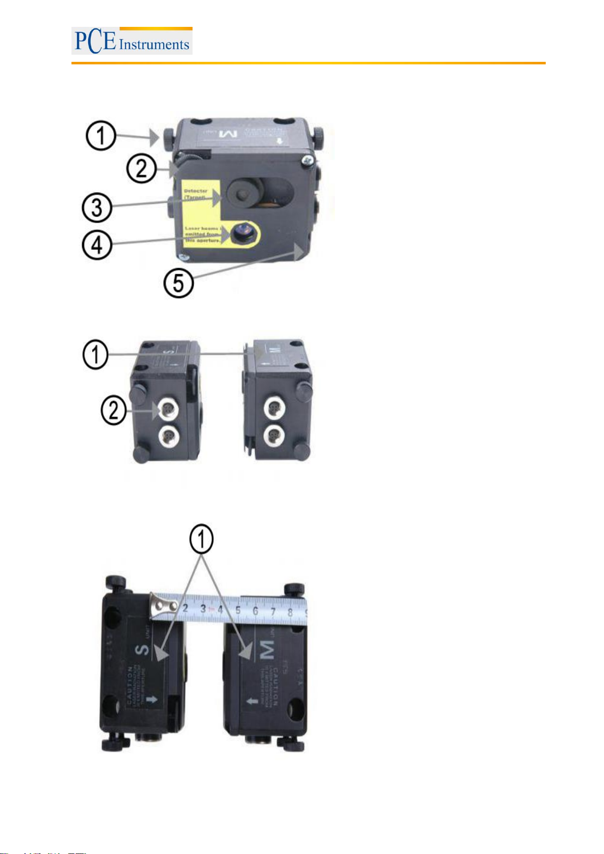
4.1 Technical description
1
Lock button
2
Vertical alignment
3
Detector / target
4
Exit hole of the laser beam
5
Horizontal alignment
Front and top view of the measurement sensors
1
Reference point
2
Cable connector socket
Measurement sensor side view
1
Reference lines to measure the
sensor distance
Top view of the measurement sensors

Manual
8
4.2 Application
The Shaft alignment tool PCE-TU 3 was designed to check and optimize the shaft alignment between
machines. In order to do so, the relative position of two coupled machines (as for example a motor and a
pump) need to be changed, in order to make sure, that the centre lines of the shaft need to be concentric
during normal operation.
4.2.1 CE-Conformity
The Shaft alignment tool is conforming to the following CE requirements:
2006/95/EC, EN 61010-1:2001, EN 60825-1:2007, 2004/108/EC, EN 61326-1:2006, EN 61326-2-2:2006,
EN 55011:2009+A1
4.3 Delivery content
1 x PCE-TU 3 display unit, 2 x probes, 2 x mounting sets for the probes, 1 x measurement tape ,
1 x battery charger, 1 x connection cable, 1 x software, 1 x USB-cable, 1 x manual, 1 x carrying case

Manual
9
4.4 Misalignment parameters
Parallel misalignment
Angular misalignment
Parallel and angular misalignment (Offset + gap)
Parallel and angular misalignment can be determined in two rectangular planes. In order to eliminate
parallel and angular misalignment, the position of the moveable machine (M) needs to be adjusted in both
planes.
For horizontally mounted machines, the following needs to be applied:
The position of the moveable machine (M) needs to be aligned in the horizontal and vertical plane.
For vertically mounted machines, the following needs to be applied:
You need to discuss the use of the movement of a moveable machine under perspectives of operation
and efficiency with the machine operator. After that, you need to determine the arrangement of correction
planes.
Stationary machines (S): The position of the machine is not changed in the course of measurement
and elimination of parallel and angular misalignment
Moveable machines (M): The position of the machine is adjusted, in order to eliminate parallel and
angular misalignment
The measurement system determines the values for parallel and angular misalignment in the coupling (in
two rectangular planes) and the corrective values which are necessary for the elimination of
misalignments of the machine bases of the moveable machine (M). The following figure shows the
misalignment and corrective values for the vertical plane.
Misalignment (vertical plane)
1
Parallel misalignment (Offset)
2
Angular misalignment
3
Corrective value
S
Stationary machine
M
Moveable machine
Manual
10
5 Machine alignment
Mount the measurement sensors to the shaft of both machines, (S) and (M)
Select the corresponding measurement program
Enter the distance between sensor (S) and sensor (M) and between the coupling and the
machine base.
Press , in order to collect measurements on three different positions of the shaft
Adjust the position of the machine bases of the moveable machine according to the determined
measurement results.
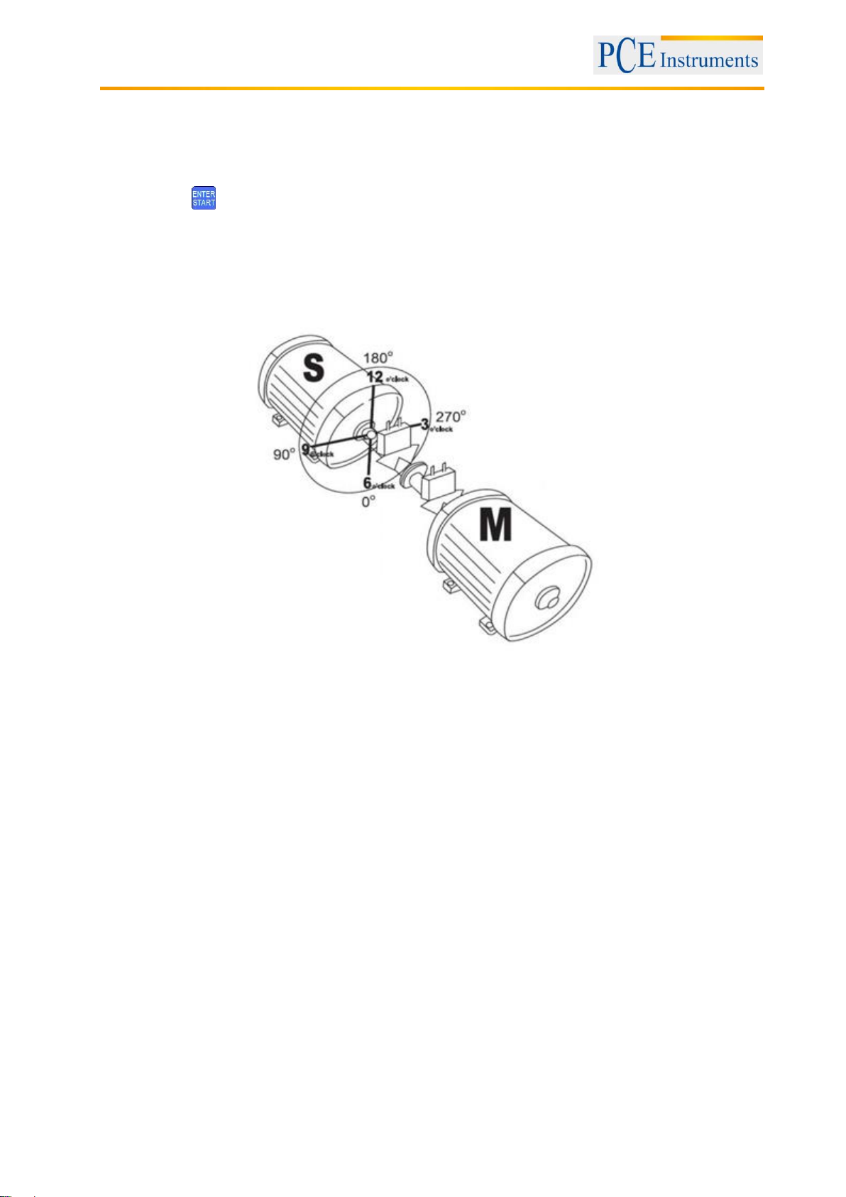
Caution!
For the implementation of the measurement, it is important to conform to the rotation direction of the
shafts and to the relative position of the sensors to the machines (S) and (M).
The figure above, shows machine (S) from the point of view of machine (M) from 12 o’clock position. The
surfaces of the measurement sensors are marked as S and Mand should be mounted to the
corresponding shaft of the machine.
5.1 Determination of measurement data
The Shaft alignment tool PCE-TU 3 is based on the measurement of a moving laser beam in the target
window of the receiving sensor while the shaft, the sensor is mounted to, is rotated.
In order to determinate the axis alignment, at least three measurements (on different positions during the
rotation of the shaft) need to be carried out. A rotation of about 180 ° is sufficient here.
If a rotation of 180 ° should not be possible due to restricted spaces or an unfavourable arrangement of
the machines, the PCE-TU 3 supports a mode for smaller rotation angles. Total rotations of 60 ° are
sufficient in this mode.

Manual
11
5.2 System setup
Before working with the Shaft alignment tool, you need to control the battery status, and recharge the
battery, if necessary.
The battery status is displayed as a small, coloured figure on the bottom of the main menu of the
instrument, while the exact battery status is available in the menu item “Setup”.
Check and clean the surface of the laser detector and the exit hole of the sensor, if necessary.
Use a cotton pad soaked in alcohol for the cleaning. Do not use solvents for the cleaning under any
circumstances.
Check date and time of the system clock and adjust them, if necessary.
5.3 Connection of the measurement sensors
There are serial ports on the display unit, as well as on the measurement sensors. The sensors need to
be connected in series to the display unit with the enclosed cables. Refer to the following figure
Serial connection of the sensors
Manual
12
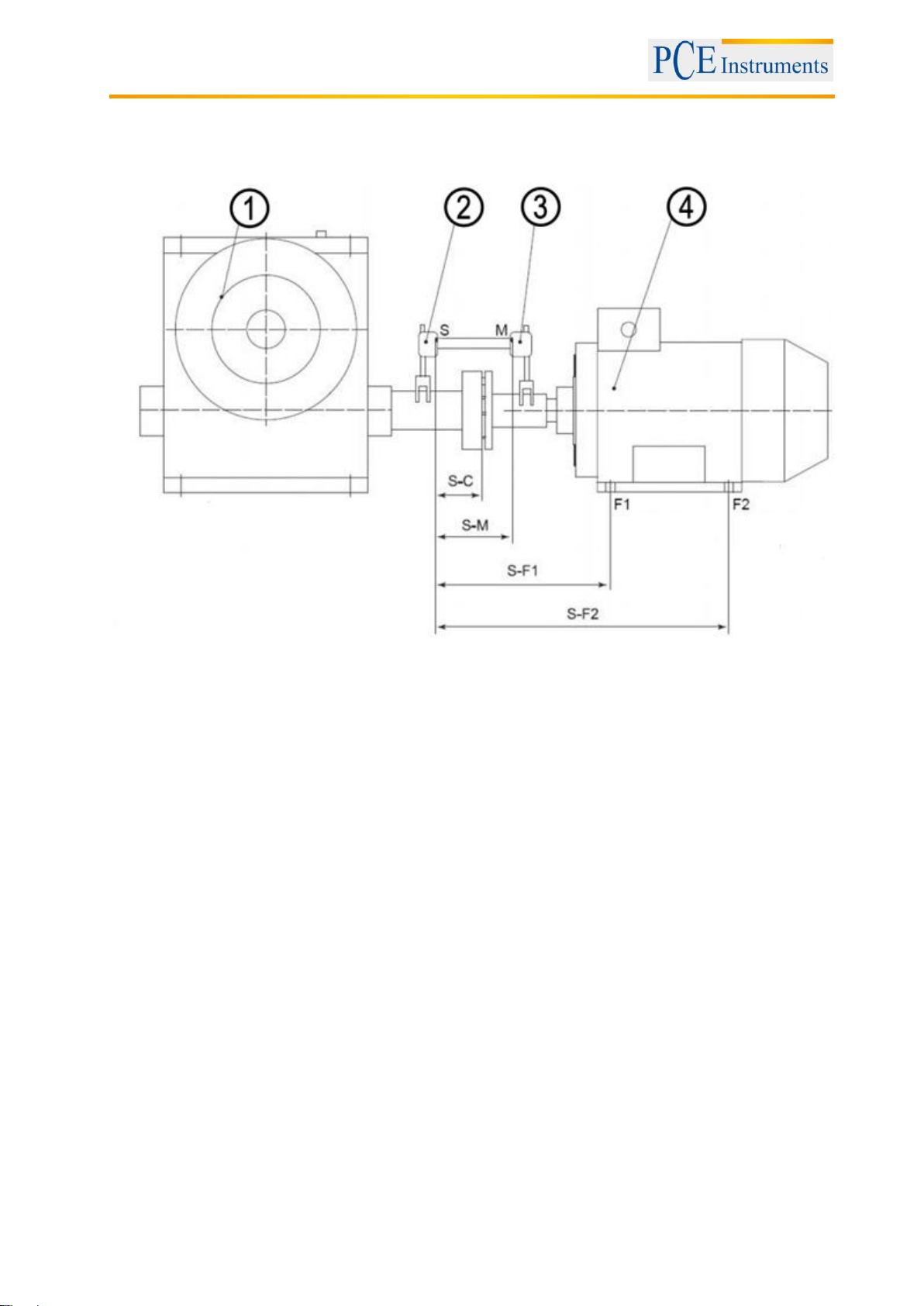
5.4 Entering of the dimensions
To achieve probable measurement results, you need to enter the distances between the sensors, the
coupling and the machine bases first. The following figures show the required dimensions for both,
horizontally and vertically mounted machines.
Horizontal alignment
1
Stationary machine
2
Sensor S
3
Sensor M
4
Moveable machine
F1
Front machine base
F2
Rear machine base
S-M
distance between the measurement sensors
S-C
distance between sensor S and the middle of the coupling
S-F1
distance between sensor S and the machine base F1
S-F2
distance between sensor S and the machine base F2 (needs to be larger than S-F1). If
the machine has three pairs of machine bases, the value can be adjusted after the
measurement. After a new measurement, you receive the corrective values for the third
pair of machine base.
Manual
13
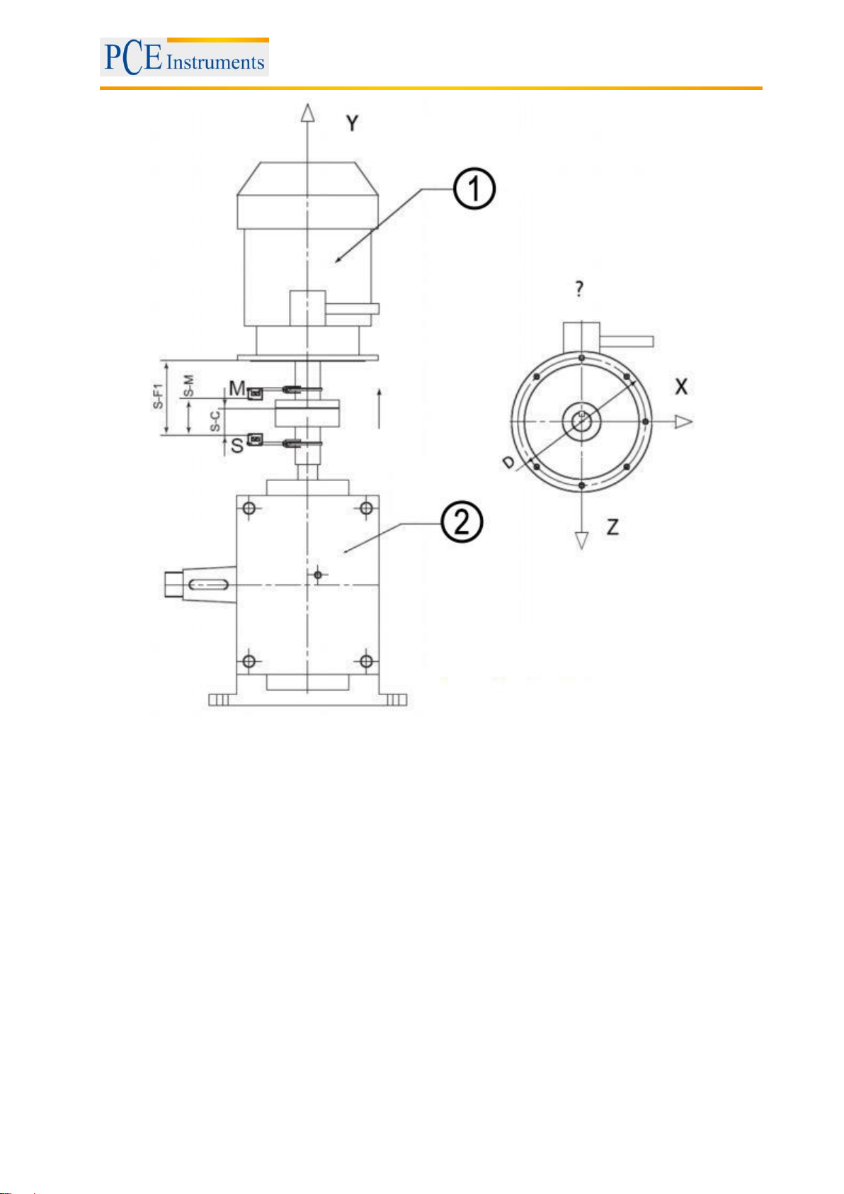
Vertical alignment
1
Moveable machine
2
Stationary machine
S-M
distance between the measurement sensors
S-C
distance between sensor S and the middle of the coupling
S-F1
distance between sensor S and the alignment plane F1
Manual
14
5.5 Rough alignment
Rough alignment should only be applied, if the axis alignment of the machines is in such a bad condition,
that the laser beams do not meet the detector during the rotation of the shaft anymore.
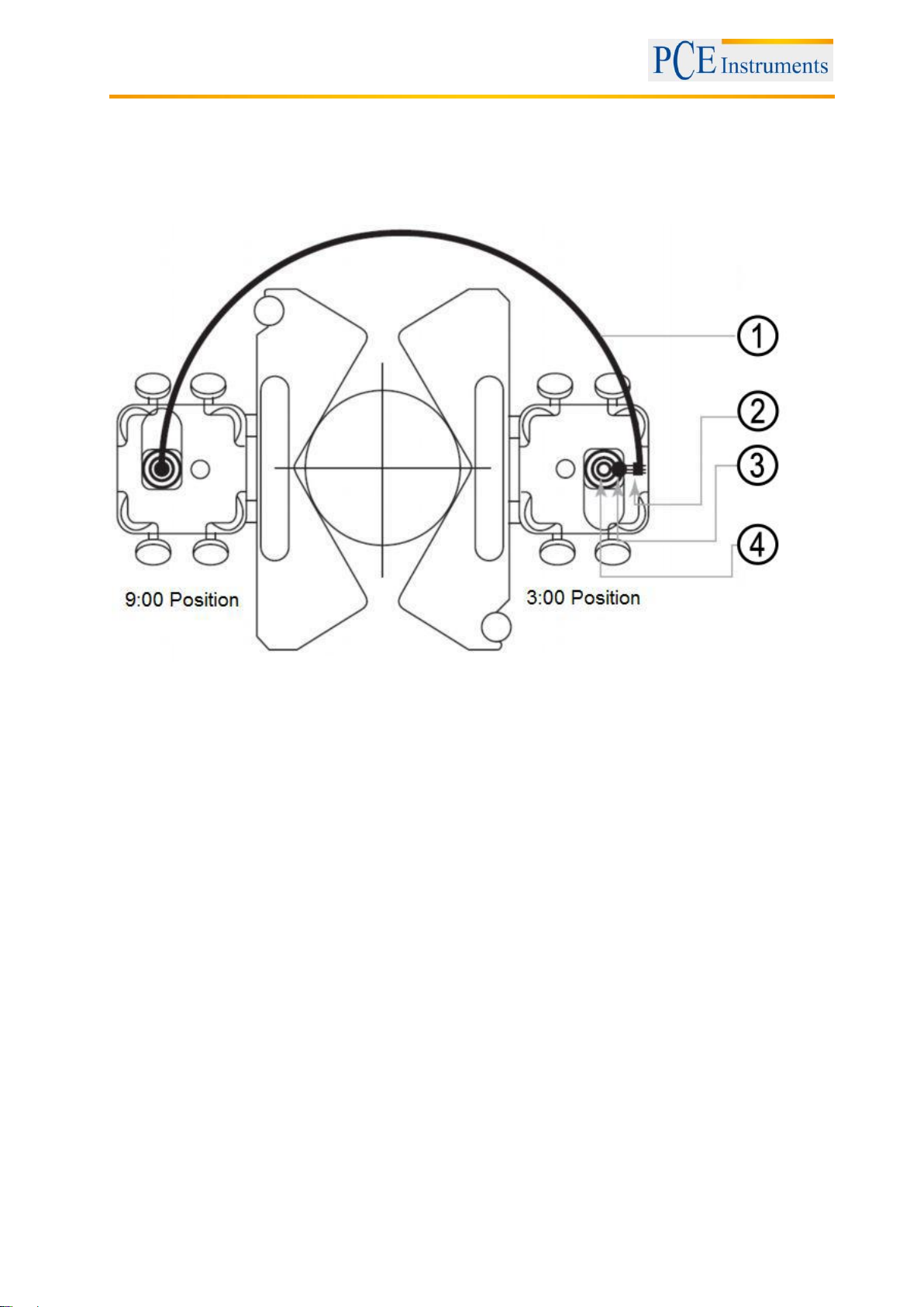
5.5.1 Rough alignment (var. 1)
View from Sensor S
1
Route of the laser beam during the rotation of the shaft
2
Laser beam outside the detector area.
3
Fixing of the laser beam halfway of the route to middle of the detector
4
Alignment of the moveable machine (M), in order to make sure the laser beams meet
(S) and (M) in the middle.
Rotate the shaft with the measurement sensors to the 9:00 position. Aim the middle of the closed
detector opening.
Rotate the shaft with the measurement sensors to the 3 o’clock position.
Check, where the laser beams meet and use the adjustment screws to fix the laser beam in the
middle of the route, to the middle of the detector (figure view from sensor).
Now align the moveable machine to the position, where the laser beam meets S and M from.
Continue with your regular measurement procedure.
Manual
15
6 Commissioning
6.1 General control keys
To close all active windows –except for the main menu –without saving, you can push the button
(serves as ESC button).
The button serves to confirm or leave entering fields and active windows (except for windows with
data entry, main screens of programs and some other).
6.2 Starting the PCE-TU 3
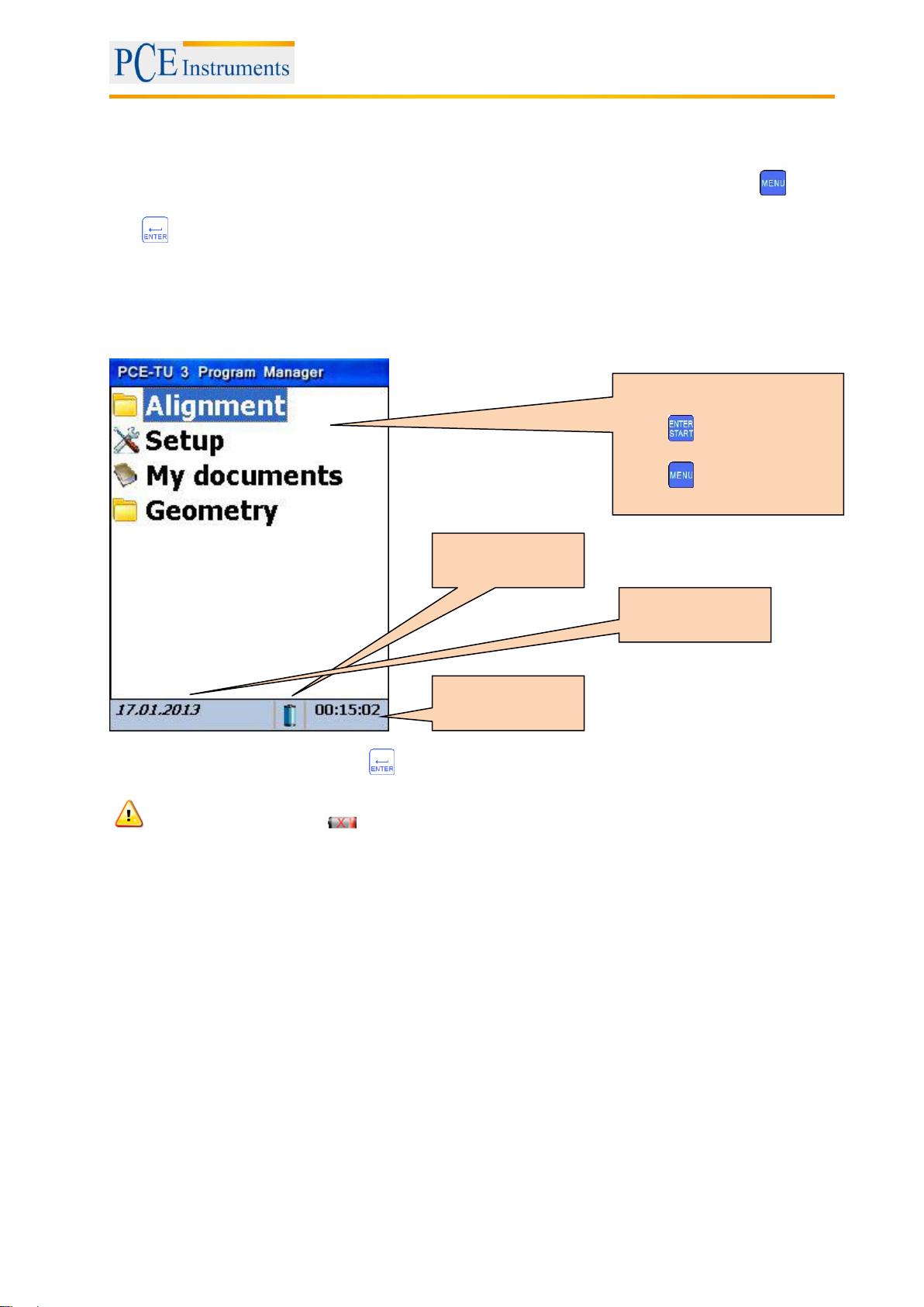
Having completed the booting, the main menu appears on the display.
To select a menu item, press
if the battery indication is flashing, you should immediately save all unsaved data and recharge
the batteries. The symbol indicates that the instrument will turn off soon.
Main Menu items
Press , to open up a list of
subfolders.
Press to close this list.
Battery indicator
System time
System date

Manual
16
7 Machine alignment
7.1 Horizontal alignment
Mount the measurement sensor, marked as S, to the shaft of the stationary machine and the
measurement sensor, marked as M, to the moveable machine. Connect the cable (described in 3.3) to
the sensors and the main unit or configure the Bluetooth interface (only possible with the Bluetooth
adaptor kit).
What should be noted in this window
Shortcuts in this window
Firstly carry out the Soft Foot Measurement
to avoid unexpected errors during the alignment
check the result after alignment by
measurement again
determination of new data
Functions in this window
Continue alignment
- Determine new data
- Continue alignment
- Change of parameters
- Change machine dimensions and
distances
Change machine dimensions and
distances
Change/add parameters
Short description of
the active parameters
Manual
17
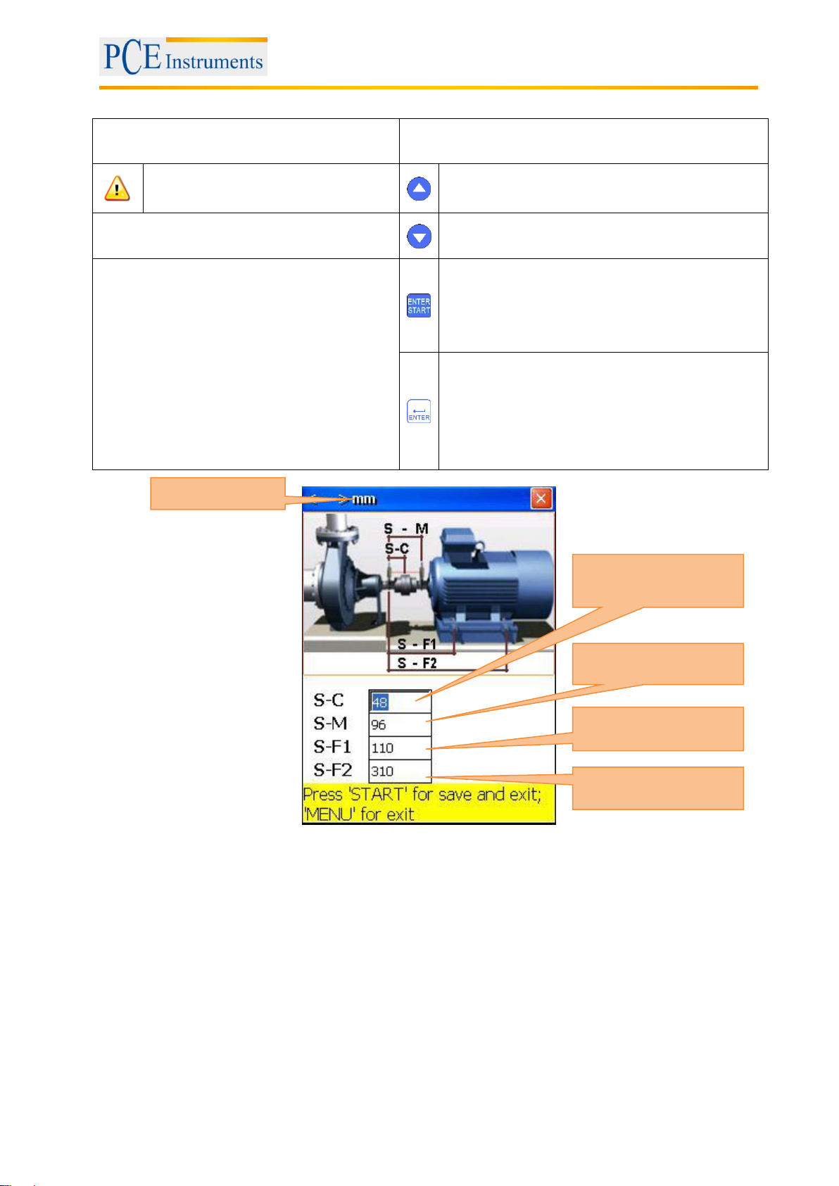
7.1.1 Enter dimensions
What should be noted in this window
Shortcuts in this window
for correct measurement results, the
following must be respected:
S-C ≤ S-F1 < S-F2
Navigate up
Functions in this window
Navigate down
- Enter distance sensor S –middle of
the coupling
- Enter distance sensor S –sensor M
- Enter distance sensor S –middle of
the coupling
- Enter distance sensor S –front
machine base
- Enter distance sensor S –rear
machine base
Save and leave and exit
Confirm entry
Measurement unit
Sensor S to middle of
the coupling
Sensor S to Sensor M
Sensor S to front
machine base
Sensor S to rear
machine base
Manual
18
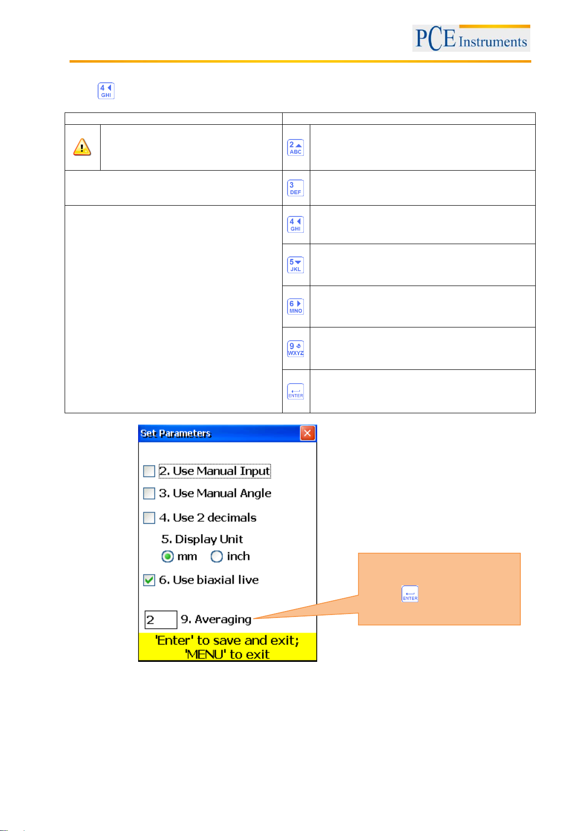
7.1.2 Change parameters
Press to change the parameters.
What should be noted in this window
Shortcuts in this window
Only use the “Biaxial Live”alignment
function with stable shaft positions,
because the smallest rotations can
lead to errors
Activate/deactivate manual data entry
Functions in this window
Activate/deactivate manual angle entry
- Manual entry or use of the sensor data
- Manual angle entry or data from
integrated inclinometer
- Selection between 2 or 3 decimal digits
- Selection between Inc and mm as
measurement unit
- Activate/deactivate “Biaxial Live”
alignment function
Use 2 or 3 decimal digits
Select between Inch and mm as measurement
unit
Activate/deactivate Biaxial Live alignment
Entry for averaging
Save and exit
Filter (averaging) settings
Press to confirm the entry

Manual
19
7.1.3 Data acquisition
Push to collect data.
What should be noted in this window
Shortcuts in this window
Before starting a new alignment
process, you need to enter dimensions
and parameters
Start again (deletes all values)
Confirmation dialogue appears
Do not change the position of
measurement units when work is
interrupted
Laser is now switched on
Functions in this window
Enter Ys-values, if manual entry is activated
- Collect measured values (up to 36)
- Select between auto sweep and
manual mode
- Manual entry of Ys- and Ym-values (if
activated)
- Manual angle entry (if activated)
- Selection of measurement unit
(mm/inch)
- Navigate through collected data
- Delete/add/replace measured values
- Restart (all values are deleted)
- Set Offset
- Save collected data
- Load collected data
Enter Ym-values, if manual entry is
activated
Enter angle, if manual entry is activated
If cursor is on the first place in the entry
field, push this button twice to reverse sign
Select the measurement unit (mm or inch)
Set parallel misalignment (Offset)
Save all data in one file (see chapter 10
„Handling of the Data Dialogue window“)
Load data from file (see chapter 10
„Handling of the Data Dialogue window“)
Delete currently selected reading
Enter new value. You have to switch to the
last value saved, to make this option
possible
Save the current value or replace already
saved values
(confirmation dialogue appears)
Navigate through data
Continue to the result window. All necessary
conditions need to be fulfilled
Open popup menu
Activate/deactivate auto-sweep. Auto-
sweep can only be activated at the
beginning of data acquisition or after restart.
Manual entry of values and inclination need
to be deactivated
Symbols and status in this window
[C]
A blinking amber-coloured “C” in the display means that currently no data can be
received from the sensors.
[R]
A blinking red “R” in the display means that you are already viewing a stored
reading. This one can be deleted or replaced. If this sign is not displayed in the
window, the current value has not been saved yet. Pressing , you can store
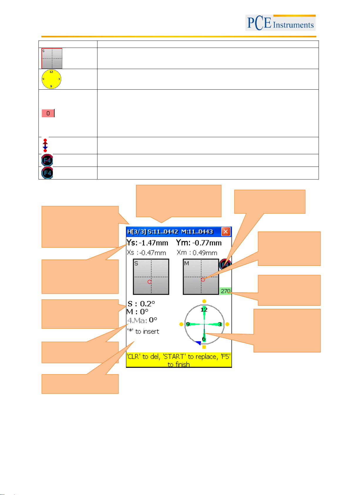
Manual
20
the value.
The absence of the laser beam position indicator and a red blinking frame of the
position indicator mean, that no laser beam meets arrives or no sensor data are
recognized.
An empty dial means that there is currently no angle established (or averaging is
not completed ) or that the rotation angle (to the next position) is too small (lower
than 6°)
A bright red indication means that the rotation angle does not meet the
requirements of the single measurement points (at least 60°).
A yellow indictaion means that the rotation angle is over 60°.
A green indication means that the rotation angle is over the recommended area
(over 90°).
This symbol means that an expanded Y-value range is used.
A crossed-out symbol means that the auto-sweep mode is deactivated.
This symbol means that the auto-sweep mode is activated.
Serial number of the
sensors. “No sensor”, if no
data can be received
Current
measurement/number of
measurements
Alignment type
H- horizontal
V - vertical
Angle of stationary and
moveable side
Manual angle
Note-Box
Dial with
measurement points
and the graphically
displayed angles
Entire rotation
angle; needs to be
larger than 60°
Laser beam position
indication
Auto-Sweep status
Table of contents
Languages:


/CK-MP instruction manual")


