Kleenmaid OCCTWB Product guide

Outdoor
Cooking Centres
Operating and assembly instructions
warranty details
Teppanyaki plate and wok burner
barbecue and pedestal
Only to be used outdoors.
FOR YOUR SAFETY.
1. If you smell gas:
Shut off gas to the
appliance, if possible.
Extinguish any open flame.
Open lid.
If odour continues,
immediately call your gas
supplier or fire department.
2. Do not store or use
petrol or other flammable
vapours and liquids in the
vicinity of this or any other
appliance.
3. A gas cylinder not
connected for use must not
be stored in the vicinity of
this or any other appliance.
Model OCCTWB / OCCTWBNG

the best you can own.
Congratulations on the purchase of your new Kleenmaid outdoor cooking centre. This
appliance has been designed and manufactured to give you years of reliable performance.
the kleenmaid story.
More than one million Australians enjoy using Kleenmaid appliances daily. Selected because of
their unique design, outstanding performance, excellent quality and unquestionable reliability,
each one is value-for-money, 100 per-cent guaranteed and at the top of its class.
attention to detail.
We are proud of our reputation for product innovation and service excellence. By dealing direct, we
can ensure that you consistently receive a high standard of customer service.
Free delivery, dedicated customer and after-sales service plus free kitchen design including
planning seminars are just a few of the ways we are setting new benchmarks for customer service
and experience.
satisfaction guaranteed.
Your new outdoor cooking centre is covered by a written five-year parts and labour warranty,
no lemon guarantee and a unique best value guarantee.
best results.
For best results, carefully read the enclosed instructions on how to assemble your new barbecue.
Correct assembly will avoid delays and unnecessary service calls.
This booklet provides you with comprehensive information to help you get to know the controls and
the features of your new outdoor cooking centre.
congratulations

GENERAL INFORMATION
33
The following minimum clearances from combustible materials must be
maintained when the appliance is in use:
top – 1000 mm, rear – 450 mm, sides – 250 mm.
Openings at the rear and sides of the appliance provide air for
combustion and must not be obstructed.
CLEARANCES
Height –lid closed 990 mm, lid open 1290 mm
Width –665 mm
Depth –lid closed 585 mm, lid open 710 mm
OVERALL DIMENSIONS
Appliance specifications can be found on the data label attached to the
side panel of the appliance body.
SPECIFICATIONS
Appliances for use with bottled gas are labelled ‘Universal LPG’ or
‘Propane’. Appliances for use with natural gas are labelled ‘Natural Gas’
and must be installed by an authorised person. Check the gas type sticker
attached to the appliance.
Your Outdoor Range barbecue is preset at the factory to operate on
bottled gas only, unless specified otherwise.
• FAILURE TO COMPLY WITH THESE
INSTRUCTIONS COULD RESULT IN A
FIRE OR EXPLOSION WHICH COULD
CAUSE SERIOUS BODILY INJURY,
DEATH OR PROPERTY DAMAGE.
• ACCESSIBLE PARTS MAY BE
VERY HOT.
• KEEP YOUNG CHILDREN AWAY.
• ANY MODIFICATION OF THIS
APPLIANCE MAY BE DANGEROUS.
• DO NOT MOVE THIS APPLIANCE
DURING USE.
• TURN OFF THE GAS SUPPLY AT THE
GAS CYLINDER AFTER USE.
• READ THE INSTRUCTIONS BEFORE
USING THE APPLIANCE.
• PARTS SEALED BY THE
MANUFACTURER MUST NOT BE
ALTERED IN ANY WAY.
• THIS APPLIANCE IS ONLY TO BE
USED OUTDOORS.
Purchased from
Date purchased
Serial No.
NOTE: Sales docket must be kept as proof of purchase date.
FOR CUSTOMER REFERENCE
(Record and file in a safe place)
General Information 3
Safety 4-5
Outdoor Areas 6
Pre-Assembly 7
Assembly 8-10
Inspection 11
Assembly –General 12-13
Operation 14
Fault Finding 15
Maintenance 16-17
Parts Diagram/List 18-19
TABLE OF CONTENTS
The regulator and hose assembly supplied with the appliance are suitable
for use with bottled gas.
This regulator is adjusted to have an outlet pressure of 2.75 kPa for
connection to a gas cylinder only. The regulator and hose assembly supplied
with the appliance must be used. Replacement regulator and hose
assemblies must be those specified by the appliance manufacturer.
When connecting the hose and regulator assembly to the gas cylinder,
take care to avoid unnecessary twisting of the flexible hose. Also, take
care to avoid a loose connection with the gas cylinder. After the assembly
has been secured, turn on the gas and check for leaks by brushing a
soap and water solution over all visible and accessible gas line connections.
Include checking those connections which were made by your supplier.
The presence of bubbles will indicate a gas escape. DO NOT TEST FOR
GAS ESCAPES WITH AN OPEN FLAME. If you are unable to correct the
leak by tightening the connections, turn off the gas and contact your place
of purchase immediately.
Always ensure the appliance is kept away from flammable materials
and the gas cylinder clear of any heat source. When changing over from
an empty gas cylinder to a full one, make sure this procedure is carried
out in a flame free atmosphere.
Inspect the gas hose assembly when exchanging the gas cylinder,
or at least once a year, whichever is more frequent. If the ‘O-Ring’or PVC
hose is cracked, cut, abraded or damaged in any way, the appliance must
not be operated. The complete assembly must be replaced if damaged
and when statutory conditions require it. Contact your place of purchase
if uncertain.
HOSE AND REGULATOR SAFETY
NEVER OPERATE THIS APPLIANCE
WITHOUT A REGULATOR.
This appliance is certified to AS 4557 by the Australian Gas Association.
Refer to data label on the appliance for certificate number.
This appliance must be used in accordance with the installation
requirements of your local gas supply authority, and the appropriate
installation standard AS5601.
GAS INSTALLATION CODES

SAFETY
44
FOR YOUR SAFETY:
• DO NOT STORE OR USE PETROL OR
OTHER FLAMMABLE VAPOURS AND
LIQUIDS IN THE VICINITY OF THIS OR ANY
OTHER APPLIANCE.
• DO NOT STORE EMPTY OR FULL SPARE
GAS CYLINDERS UNDER OR NEAR THIS
OR ANY OTHER APPLIANCE.
• KEEP THE GAS HOSE AWAY FROM HOT
SURFACES. PROTECT GAS HOSE FROM
DRIPPING GREASE.
AVOID UNNECESSARY TWISTING OF
HOSE. VISUALLY INSPECT HOSE PRIOR TO
EACH USE FOR CUTS, CRACKS, EXCES-
SIVE WEAR OR OTHER DAMAGE.
REPLACE HOSE, IF NECESSARY.
• NEVER TEST FOR GAS LEAKS WITH A LIT
MATCH OR OPEN FLAME.
• NEVER LIGHT APPLIANCE WITH LID
CLOSED.
• NEVER LEAN OVER COOKING
SURFACE WHILE LIGHTING APPLIANCE.
• USE GOOD QUALITY INSULATED OVEN
MITTS WHEN OPERATING APPLIANCE.
• NEVER ALTER OR MODIFY THE
REGULATOR OR GAS SUPPLY ASSEMBLY.
• THIS APPLIANCE MUST NOT BE USED
INDOORS.
DANGER – IF YOU SMELL OR HEAR
THE HISS OF ESCAPING GAS FROM
THE GAS CYLINDER:
• KEEP CLEAR OF THE GAS CYLINDER.
• TURN ALL CONTROLS ON THE
APPLIANCE TO ‘OFF’.
•EXTINGUISH ANY OPEN FLAME.
•REMOVE LID OR OPEN HOOD.
•IF ODOUR CONTINUES, IMMEDIATELY
CALL YOUR GAS SUPPLIER OR FIRE
DEPARTMENT.
READ CAREFULLY BEFORE
ASSEMBLING AND OPERATING
YOUR OUTDOOR RANGE BARBECUE.
NEVER CONNECT AN UNREGULATED
GAS CYLINDER TO THIS APPLIANCE.
• NEVER STORE YOUR
GAS CYLINDER INDOORS.
• FOR STORAGE AND CYLINDER
EXCHANGE, DISCONNECT HOSE AT THE
CYLINDER ONLY –
DO NOT DISCONNECT HOSE FROM
THE APPLIANCE.
DO NOT use this appliance in garages, porches, breezeways, sheds or
other enclosed areas. The Outdoor Range barbecue is to be used
OUTDOORS ONLY. Refer to page 6. It is not intended to be installed in
or used on recreational vehicles and/or boats and should not be placed
under any surface that will burn. Do not obstruct the flow of combustion
and ventilation air around the appliance housing while in use.
LOCATION OF YOUR OUTDOOR RANGE
Keep children away from this appliance during use and until it has cooled
after you are finished. Do not allow children to operate appliance or to
swing on handle.
PROTECT CHILDREN
The gas cylinder should be filled by a reputable gas dealer, or exchanged at
a reputable gas cylinder exchange outlet. Gas cylinders should be
visually inspected and re-qualified periodically.
Always keep gas cylinder in an upright position. Always close the
cylinder valve when the appliance is not in use.
Do not subject the gas cylinder to excessive heat.
If you store this appliance indoors, ALWAYS disconnect and remove gas
cylinder FIRST, and store gas cylinder safely outside. Gas cylinders
must be stored outdoors in a well ventilated area out of reach of children,
and must not be stored in a building, garage or any other enclosed area.
This is a low pressure appliance and must only be used with the hose and
regulator supplied.
This appliance is designed for use with a 9 kg gas cylinder. Ensure
gas cylinder conforms to Australian Standard AS2469 and is less than 10
years old.
DO NOT CONNECT THIS APPLIANCE TO A GAS
CYLINDER LESS THAN OR EXCEEDING THIS CAPACITY.
GAS CYLINDER USE AND APPLIANCE SAFETY
SERVICING
ANY OF THE FOLLOWING SIGNS MAY
INDICATE THAT THE APPLIANCE IS NOT
OPERATING PROPERLY AND MAY NEED
SERVICING:
•EXCESSIVE YELLOW FLAME.
•IRREGULAR SIZE OF FLAME
ACROSS BURNER.
•‘POPPING’OF FLAME.
•SOOTING.
•ABNORMAL NOISE(S).
•HISSING SOUND.
NOTE: Before requesting service,
please refer to page 15 ‘Fault Finding’.
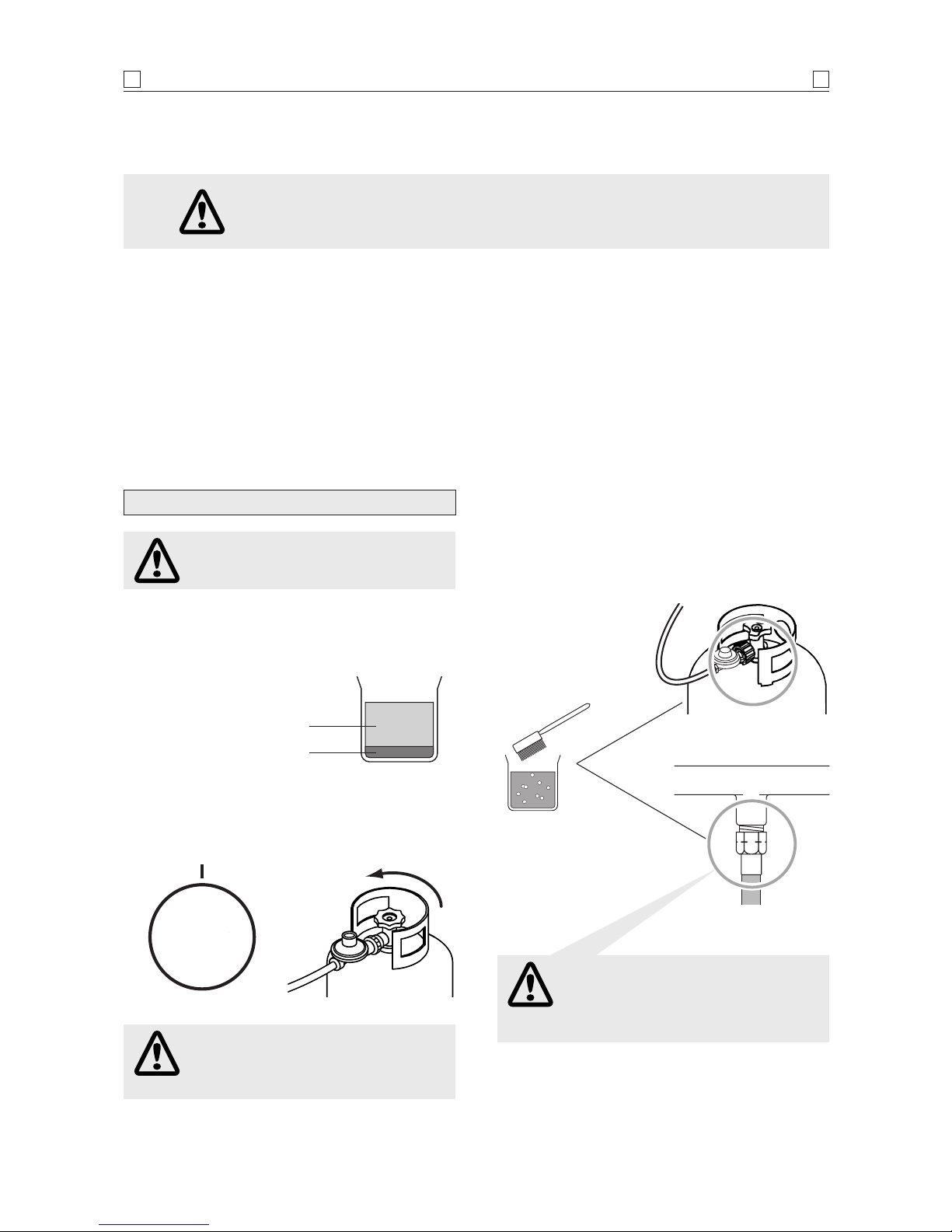
NEVER TEST FOR LEAKS WITH A FLAME.
Prior to first use, and at the beginning of each new season (or, if using
bottled gas, whenever gas cylinder is changed), you must check for gas
leaks. Follow these steps:
1. Make soap solution by mixing one part liquid detergent and one
part water.
2. Turn burner control(s) to ‘OFF’, then turn on gas at source.
3. Apply the soap solution to all visible and accessible gas connections
including the gas cylinder. Bubbles will appear in the soap solution
if connections are not properly sealed. Tighten or rectify as necessary.
Refer to page 5 for further details.
4. If you have a gas leak you cannot rectify, turn off the gas at the
source. Contact the manufacturer for assistance.
Refer to back cover.
CHECKING FOR GAS LEAKS

SAFETY
55
NEVER CHECK FOR LEAKS WITH
A FLAME.
IF YOU HAVE A GAS LEAK YOU
CANNOT RECTIFY, TURN OFF THE GAS
AT THE SOURCE. CONTACT THE
MANUFACTURER.
WHEN CHANGING THE GAS HOSE FOR
ANY REASON, ALWAYS CHECK THE
CONNECTION TO THE MANIFOLD FOR
GAS LEAKS BEFORE OPERATING THE
APPLIANCE.
ALWAYS CHECK FOR GAS LEAKS EACH TIME
YOU USE YOUR OUTDOOR RANGE BARBECUE.
1. Make liquid detergent solution by mixing one (1) part liquid
detergent and four (4) parts water.
2. Turn burner control knob(s) to ‘OFF’, then turn on gas at
source.
CHECKING FOR GAS LEAKS
You should follow this procedure after any of the following:
•Not having used the appliance for an extended period of time,
•Initial assembly of the appliance,
•Any disconnection and reconnection of hose assembly,
•Changing gas cylinder,
•Upon re-connecting gas cylinder after it has been disconnected for storage.
4 parts water Gas cylinder connection
Manifold connection
Open
1 part liquid
detergent
3. Apply the liquid detergent solution to all visible and accessible
gas connections, including the connection to the gas cylinder.
Bubbles will appear in the liquid detergent solution if
connections are not properly sealed. Tighten or rectify as
necessary.
OFF
IGN HI
LO

The following diagrams are examples of outdoor areas.
These same principles apply to canopy or shaded cloth areas.
THIS APPLIANCE SHALL ONLY BE USED IN AN ABOVE GROUND OPEN AIR SITUATION WITH NATURAL
VENTILATION, WITHOUT STAGNANT AREAS, WHERE GAS LEAKAGE AND PRODUCTS OF COMBUSTION
ARE RAPIDLY DISPERSED BY WIND AND NATURAL CONVECTION.
ANY ENCLOSURE IN WHICH THE APPLIANCE IS USED SHALL COMPLY WITH ONE OF THE FOLLOWING:
OUTDOOR AREAS
66
•AN ENCLOSURE WITH WALLS
ON ALL SIDES, BUT AT LEAST
ONE PERMANENT OPENING AT
GROUND LEVEL AND NO
OVERHEAD COVER
•WITHIN A PARTIAL
ENCLOSURE THAT INCLUDES
AN OVERHEAD COVER AND NO
MORE THAN TWO WALLS
•WITHIN A PARTIAL
ENCLOSURE THAT INCLUDES
AN OVERHEAD COVER AND
MORE THAN TWO WALLS, THE
FOLLOWING SHALL APPLY:
(i) AT LEAST 25% OF THE TOTAL
WALL AREA IS COMPLETELY
OPEN: AND
(ii) AT LEAST 30% OF THE
REMAINING WALL AREA IS
OPEN AND UNRESTRICTED
•IN THE CASE OF BALCONIES,
AT LEAST 20% OF THE TOTAL
OF THE SIDE, BACK AND FRONT
WALL AREAS SHALL BE AND
REMAIN OPEN AND
UNRESTRICTED
•DO NOT USE THIS APPLIANCE IN
GARAGES, PORCHES, BREEZE-
WAYS, SHEDS OR OTHER
ENCLOSED AREAS.
THIS APPLIANCE IS TO BE
USED OUTDOORS ONLY.
Refer below.
•THE APPLIANCE IS NOT
INTENDED TO BE INSTALLED IN
OR USED ON RECREATIONAL
VEHICLES AND/OR BOATS AND
SHOULD NOT BE PLACED
ADJACENT TO OR UNDER ANY
SURFACE THAT WILL BURN.
•DO NOT OBSTRUCT THE FLOW
OF COMBUSTION AND
VENTILATION AIR AROUND
THE APPLIANCE HOUSING
WHILST IN USE.
Both ends
open
30% or more in total of
the remaining wall area
is open and unrestricted
30% or more in total of
the remaining wall area is
open and unrestricted
Open side at
least 25% of total
wall area
Open side at
least 25% of total
wall area

PRE-ASSEMBLY
77
Standard Phillips-head screwdriver.
Adjustable spanner (open-end shifter).
TOOLS YOU WILL NEED
Description Qty
Trolley side panel –right 1
Trolley side panel –left 1
Trolley rear panel 1
Castor seat
–1 x left rear, 1 x left front, 1 x right rear, 1 x right front 4
Castors 4
Bottom shelf 1
Trolley bracket –front 1
Gas cylinder pull-out tray 1
Body support bracket 2
Trolley separation panel 1
Doors 2
Body assembly 1
Hardware pack 1
Hot plate 1
Pot support 1
Door hinge
–1 x top left, 1 x top right 2
Door guide 1
Grease tray 1
Grease drain tube 1
Towel rack 1
Spice rack 1
CARTON CONTENTS
Before attempting to assemble your barbecue, check that all the
necessary parts have been included using the parts list opposite.
Inspect barbecue and trolley parts as you proceed.
Contact your place of purchase for assistance regarding
replacement of any damaged or missing parts. Supplier contact
details are on the back cover of the instruction manual.
Do not assemble or operate a barbecue that appears damaged.
Check that the barbecue supplied is correct for the gas type
being used. There is a label on the side panel of the barbecue
above the gas connection. Barbecues for use with gas cylinders
are labelled ‘Universal LPG’. Barbecues for use with natural gas
are labelled ‘Natural Gas’.
CHECK BARBECUE FOR ANY DAMAGE
While it is possible for one person to assemble the barbecue,
we recommend asking for the assistance of another person when
manoeuvring some of the larger or heavier pieces.
GENERAL
1. Flatten cardboard packaging and use this as a protective
work surface to assemble upon.
2. Some protective coating may need to be removed from
components prior to assembly.
3. Tighten screws and nuts unless otherwise specified.
4. Pre-screwing of connection points for securing the side
shelves will assist in securing shelves smoothly.
ASSEMBLY TIPS

ASSEMBLY
88
LEFT
SIDE
Phillips flat-head screw 1/4" x 1/2"
Qty: 4
Phillips flat-head screw 3/16" x 3/8"
Qty: 4
Attach side panels to bottom shelf.
2
Phillips-head screw 1/4" x 1/2"
Qty: 16
Attach castor seats to side panels.
NOTE: Castor seats are labelled for
correct location
Repeat for right side.
1
A
B
Door magnets
to front
LF
B
RF
Attach castor wheels to castor seat.
Attach door guide
3
Phillips-head screw 3/16" x 3/8"
Qty: 2
Door guide
A
B
A
B
B
A

ASSEMBLY
99
Phillips-head screw 3/16" x 3/8"
Qty: 12
Flange nut 3/16"
Qty: 12
Phillips-head screw 1/4" x 1/2"
Qty: 4
Rear panel
Attach the trolley bracket front and rear panel.
4
Attach gas cylinder tray.
TIGHTEN ALL SCREWS.
5
RIGHT
SIDE
Phillips-head screw
3/16" x 3/8"
Qty: 6
Flange nut 3/16"
Qty: 6
Screw
Attach body support brackets and trolley
separation panel.
6
Trolley bracket front.
NOTE: Door magnets to bottom
Nut x3
Door hinge bracket,
top left
Door hinge bracket,
top left

A S S E M B L Y
10 10
Phillips-head screw
1/4" x 13/16"
Qty. 4
Attach barbecue body to trolley.
NOTE: Release regulator from underneath the
body by cutting the cable tie. Feed regulator
through the hole in the trolley separation panel.
After assembly is complete close the hatch
(located underneath) around the gas hose.
Refer to page 13 for installation of grease tray and grease
tube.
8
Phillips-head screw
3/16" x 1/4"
Qty: 4
Phillips-head screw
3/16" x 3/8"
Qty: 4
Attach top right and left door hinges / doors. Insert the bottom
door hinge pin into the lower door hinge bracket holes.
Depress the spring loaded top door hinge pin and line up
with the top hinge bracket holes, and release the pin.
Attach door handles and towel rack to the inside panel
of the left door.
7
AB
A
A
B
Towel rack
Locate spice rack into
slots inside left door
Note: Change of screws for securing Towel Rack:
4 x self tapping screws have been attached to original hardware
pack to replace original 4 x metal threaded 3/16”screws. Please
use self tappers to secure towel rack. Original screws may still
be enclosed in hardware pack and will remain after assembly.

INSPECTION
11 11
Ensure gas source is turned off or is disconnected and all burner
control knobs are set to ‘OFF’. Open the lid and remove the hot
plate. Push the electronic igniter. You should hear a ‘clicking’
sound. You should see a blue spark within the gas collector
box. If a spark is present the electrode tips are properly positioned.
If no spark is seen, the spark gap needs to be
adjusted as follows:
•Using an adjustable spanner, loosen the inside nut until the
gas collector box can be turned upward. If the gap between
the spark electrode tip and receiver is more than 4 - 5 mm use
long nose pliers to gently squeeze the gas collector box to
narrow gap. Return the gas collector box to its original
position, secure the inside nut and try the electrode check
again.
•CHECK PERFORMANCE OF
BURNERS PRIOR TO INSTALLING
HOT PLATE COMPONENTRY.
Refer to page 14 for lighting instructions.
•DO NOT SMOKE WHEN ATTEMPTING
TO IGNITE APPLIANCE.
•NEVER USE VOLCANIC ROCK,
HEAT BEADS OR OTHER MATERIAL.
•ALWAYS USE PROTECTIVE GLOVES
WHEN HANDLING HOT COMPONENTS.
•Open pot burner lid.
•Push electronic ignition button. Look for a spark between tip
of electrode and burner.
•If you don't see a spark from pot burner electrode, adjust
gap between electrode and burner surface to 4 - 5 mm.
ELECTRODE CHECK –POT BURNER
This test will ensure the spark electrode tips are correctly positioned
so the appliance lights easily and properly.
ELECTRODE CHECK –HOT PLATE BURNER
+
-
4-5 mm
spark gap
Gas collector
box
Spark
electrode tip
Spark
receiver
Inside
nut
•Unscrew igniter cap from control panel.
•Place supplied AA battery into the igniter slot with positive
pole facing you.
•Position the cap and spring over the AA battery and tighten
onto control panel.
INSTALL IGNITER BATTERIES
AA
battery
Spring
Igniter
cap
Contact

ASSEMBLY–GENERAL
12 12
TEST FOR LEAKS WITH A
SOAP SOLUTION, NEVER WITH AN
OPEN FLAME (Refer to pages 4 and 5).
CONNECTING TO, AND DISCONNECTING
FROM GAS SOURCE
CONNECTING TO GAS SOURCE
1. Place gas cylinder into the gas cylinder tray and face the
gas cylinder valve to the left rear corner. Secure with
wing bolt.
2. Attach cylinder connection
device of regulator and hose
assembly to cylinder
valve outlet.
Tighten firmly.
3. Open gas cylinder
valve fully to allow
gas to flow.
4. Leak test all accessible
connections thoroughly
using a soapy water
solution prior to lighting the appliance.
Refer to Safety information, pages 4 and 5.
5. If a leak is found, turn gas cylinder valve off and do not use
appliance until repairs or replacement can be made.
DISCONNECTING FROM GAS SOURCE
1. Turn burner control ‘OFF’.
2. Turn gas cylinder valve off fully.
3.
Detach regulator assembly from gas cylinder
valve.
This appliance is also certified for use on natural gas. Contact
the manufacturer for advice in relation to using this appliance on
natural gas. Refer to back cover.
Appliances for use on natural gas must be installed by an
authorised person.
NATURAL GAS INSTALLATION
IMPORTANT: Before connecting and disconnecting
appliance to gas source, ensure burner controls are
in ‘OFF’position.
NOTE: The ‘OFF’position on the control panel is
identified by either a small black dot / a short vertical
black line / or the word ‘OFF’.
When the marking, or the word ‘OFF’printed on
the control knob, aligns with the printed marking on
the control panel, then the burner is in the fully off
position.
CAUTION: When the appliance is not in use, the gas
must be turned off at the gas cylinder.
Familiarise yourself with the general information and safety
guidelines located at the front of this booklet. Check to see that
gas cylinder is filled and that end of each burner tube is properly
located over each valve orifice. Set burner controls to ‘OFF’
position.
ENSURING BURNER CONTROLS ARE OFF
•DISCONNECT AND REMOVE GAS
CYLINDER WHEN MANOEUVRING
APPLIANCE OVER UNEVEN SURFACES
OR CARRYING UP AND DOWN STAIRS.
•IF THIS INFORMATION IS NOT
FOLLOWED EXACTLY, A FIRE
CAUSING DEATH OR SERIOUS INJURY
MAY OCCUR!
•DO NOT STORE A SPARE GAS
CYLINDER UNDER OR NEAR THIS
APPLIANCE.
•THIS APPLIANCE IS ONLY TO BE
USED OUTDOORS.
Direction for
tightening

Before first use and at the beginning of each season:
1. Please read Safety, Lighting and Operating instructions
carefully.
2. Check gas valve orifices, burner tubes and burner ports for
any obstructions. eg. spiders, webs, insects.
3. Check and ensure gas cylinder is full.
4. Ensure all connections are securely tightened.
Check for gas leaks. Refer to pages 4 and 5.
NOW YOUR OUTDOOR RANGE APPLIANCE
IS READY TO USE
ASSEMBLY–GENERAL
13 13
NOTE: Side shelves are supplied separately.
The side shelves may be installed to any of the Modular Outdoor
Kitchen modules, Modular barbecue, Outdoor Range module and
Sink / Workstation module, depending on the configuration
preferred.
Refer to the instructions included in the ‘Side Shelf’pack.
INSTALL SIDE SHELVES
•Slide grease tray into position as shown in diagram.
•Remove the hot plate and position
the grease tube in the slot at the
front of the fire box.
INSTALL GREASE TRAY AND GREASE TUBE
Grease tube

‘HI’setting –Use this setting only for warm up, for searing
steaks and chops, and for burning food residue from the grill
plates after the cooking is over. Rarely, if ever, do you use the
‘HI’setting for extended cooking.
‘MED’setting (mid-way between ‘HI’and ‘LO’). Use this setting
for most grilling, and for cooking hamburgers and vegetables.
‘LO’setting –Use this setting when cooking very lean cuts such
as fish.
Actual cooking surface temperatures vary with outside temperature
and the wind conditions.
COOKING TEMPERATURES
If igniters fail to produce a spark at the electrode, burners can be
lit with a match.
1. HOT PLATE BURNER
Turn right burner control to ‘HI’position then position
match into lighting tube provided at the rear of cooking surface.
The burner will light immediately.
2. POT BURNER
Turn left burner control to ‘HI’position then light burner
directly with a match.
MANUAL LIGHTING
NOTE: Burners are fitted with a thermal shut-off
feature. After ignition, the control knob must continue
to be depressed at the ‘HI’position. Refer to step 5.
1. Open the lid before attempting to
light burners.
2. Set burner control knobs to ‘OFF’
and open the gas cylinder valve.
3. Push and turn required burner control
knob to ‘IGN’.
4. Push the control knob in and hold to
ignite the burner.
5. Once the burner is ignited,
continue to depress the control
knob and rotate to ‘HI’position.
Hold for 10 seconds to bypass the
thermal shut-off.
6. If burner does not light, turn burner
control knob to ‘OFF’, wait 5 minutes
for gas to clear, then retry.
7. Adjust burner control knobs to
the
desired cooking temperature.
8. If ignition cannot be achieved, perform electrode check
procedure. Refer to page 11.
HOT PLATE / POT BURNER IGNITION
•THE POT BURNER IS DESIGNED FOR
USE WITH A WOK UP TO 360 mm
DIAMETER AND COOKING POTS UP TO
200 mm DIAMETER.
•USE OF VERY LARGE POTS MAY
RESULT IN DISCOLOURATION OF THE
SURFACE FINISH, OR CAUSE POOR
COMBUSTION.
Match
OPERATION
14 14
•THE LID MUST BE IN THE OPEN
POSITION FOR LIGHTING.
•DO NOT SMOKE AT ALL TIMES
WHEN ATTEMPTING TO IGNITE THE
APPLIANCE.
•CAUTION: DO NOT MOVE TROLLEY
WHILE APPLIANCE IS IN OPERATION.
•CAUTION: DO NOT LEAVE THIS
APPLIANCE UNATTENDED WHEN
BURNER/S IS ALIGHT.
LIGHTING PROCEDURES
OFF
IGN
HI
LO
OFF
IGN HI
LO
BURN-OFF
Before cooking on your Outdoor Range for the first time, burn-off
any residual oils or foreign matter from the cooking plate.
ENSURE THE LID IS OPEN, and operate at ‘HI’setting for
approximately 15 minutes. Allow to cool then wash plate thoroughly
with soap suds and scrubbing brush. Rinse thoroughly and
wipe clean with a cloth. Your plate is ready to use.
PREHEATING
It is necessary to preheat the plate before cooking. Operate the
burner under the cooking surface to be used at ‘HI’for approximately
10 minutes before cooking.
OPERATING PROCEDURE
Lighting
tube

FAULT FINDING
15 15
•SHOULD A FLASHBACK FIRE OCCUR
IN OR AROUND BURNER TUBES,
FOLLOW THE INSTRUCTIONS BELOW.
FAILURE TO COMPLY WITH THESE
INSTRUCTIONS COULD RESULT IN
•A FIRE OR EXPLOSION THAT COULD
CAUSE SERIOUS BODILY INJURY,
DEATH, OR PROPERTY DAMAGE.
•SHUT OFF GAS SUPPLY TO
APPLIANCE.
•TURN THE CONTROL KNOBS TO OFF
POSITION.
•OPEN THE APPLIANCE LID.
PUT OUT ANY FLAME WITH A FIRE
EXTINGUISHER.
•ONCE THE APPLIANCE HAS COOLED
DOWN, CLEAN THE BURNER TUBES
AND BURNERS ACCORDING TO THE
CLEANING INSTRUCTIONS IN THIS
OPERATION MANUAL.
1. Turn gas off at source and turn burner control knobs to
‘OFF’. Wait at least five (5) minutes for gas to clear, then
retry.
2. If your Outdoor Range barbecue still fails to light, check gas
supply and connections.
3. Repeat lighting procedure. If the appliance still fails to
operate, turn the gas off at source, turn the control knobs to
‘OFF’, then check the following:
•MISALIGNMENT OF BURNER TUBES
OVER ORIFICES
Correction: Reposition burner tubes over orifices.
•OBSTRUCTION IN GAS LINE
Correction: Remove fuel line from appliance. Do not
smoke! Open gas supply for one second to clear any
obstruction from fuel line. Close off gas supply at source
and reconnect fuel line.
•PLUGGED ORIFICE
Correction: Remove burners. Carefully lift each burner up
and away from gas valve orifice. Remove the orifice from
gas valve and gently clear any obstruction with a fine wire.
Then reinstall all orifices, burners and cooking components.
If an obstruction is suspected in gas valves or manifold,
contact your place of purchase or manufacture.
•OBSTRUCTION IN BURNER TUBES
Correction: Follow burner tube cleaning procedure on page 18
of this operation manual.
•MISALIGNMENT OF IGNITER ON BURNER
Correction: Check for proper position of electrode tip as
shown on page 11. The gap between spark electrode tip
and spark receiver should be approximately 4 - 5 mm.
Adjust if necessary. With gas supply closed and all control
knobs set to ‘OFF’press the electric igniter cap and check
for the presence of a spark at electrode.
•DISCONNECTED ELECTRIC WIRES
Correction: Inspect the igniter junction box found behind the
control panel. Connect loose electric wires to junction box
and try to light appliance.
•WEAK AA BATTERY
Correction: Unscrew igniter cap and replace battery.
IF THIS APPLIANCE FAILS TO LIGHT
CAUTION: If burners go out during operation, close
gas supply at source, and turn all gas valves off.
Open lid and wait 5 minutes before re-attempting to
light (this allows accumulated gas fumes to clear).
CAUTION: Should grease fire occur, close gas supply
at source, turn off all burners and remove food until
fire is out.
KEEP THE VENTILATION OPENINGS OF THE
CYLINDER ENCLOSURE FREE AND CLEAR FROM
DEBRIS.

MAINTENANCE
16 16
Before initial use and periodically, wash the cooking plates in a mild
soap and warm water solution. You can use a wash cloth or
vegetable brush to clean the cooking plates.
It is recommended cooking plates be coated with a thin layer
of cooking oil on a regular basis to prevent rusting. Slight rusting
can be removed with a scrubbing brush before use.
CLEANING THE COOKING PLATE
Proper care and maintenance will keep your Outdoor Range in top
operating condition and prolong its life. Follow these cleaning
procedures on a timely basis and your Outdoor Range will stay
clean and operate with minimum effort.
CAUTION: Be sure your Outdoor Range is off and
cool before cleaning.
CLEANING AND MAINTENANCE
Before initial use and periodically thereafter we suggest you wash
your Outdoor Range using a mild soap and warm water solution.
You can use a wash cloth or sponge for this process. Do not use
a stiff wire or brass brush. These will scratch stainless steel and
chip painted surfaces (varies by model) during the cleaning
process.
CLEANING EXTERIOR SURFACES
To reduce the chance of fire, the grease receptacle should be
visually inspected before each appliance use. Remove any
grease and wash grease receptacle with a mild soap and warm
water solution.
NOTE: Grease fires are not covered by warranty.
CLEANING THE GREASE TRAY RECEPTACLE
FAILURE TO READ AND FOLLOW THE
‘USE AND CARE INSTRUCTIONS’COULD
RESULT IN A FIRE OR EXPLOSION
THAT COULD CAUSE SERIOUS BODILY
INJURY, DEATH OR PROPERTY
DAMAGE.
Stainless steel over time will be affected by ‘tea staining’(the
brown discolouration of some stainless steel).
Tea staining can be reduced by washing the surface with
mild detergent and warm water and then rinsing with clean cold
water. We recommend the surface be wiped dry with a clean
cloth.
CARE FOR STAINLESS STEEL
IN COASTAL AREAS, FREQUENT
CLEANING AND THE USE OF A COVER
IS RECOMMENDED TO PROLONG THE
LIFE OF THE APPLIANCE.
SALTY AIR WILL ADVERSELY AFFECT
EXPOSED PARTS.
DO NOT USE OVEN CLEANER TO CLEAN
THE OUTDOOR RANGE.
SOME PROPRIETORY BARBECUE
CLEANERS MAY AFFECT / DAMAGE
SOME OF THE SURFACE COATINGS
USED ON THIS APPLIANCE.
READ THE CLEANER INSTRUCTIONS
CAREFULLY.
IT IS RECOMMENDED TO TEST FIRST IN
AN INCONSPICUOUS PLACE.
GENERALLY WE RECOMMEND ONLY
WARM SOAPY WATER FOR CLEANING
THIS APPLIANCE.

•KEEP APPLIANCE AREA CLEAR AND
FREE FROM COMBUSTIBLE MATERIALS,
GASOLINE AND OTHER FLAMMABLE
VAPOURS AND LIQUIDS.
•DO NOT OBSTRUCT FLOW OF AIR FOR
COMBUSTION AND VENTILATION.
•KEEP VENTILATION OPENINGS OF
CYLINDER ENCLOSURE CABINET FREE
AND CLEAR OF DEBRIS.
•VISUALLY CHECK BURNER FLAMES
OCCASIONALLY TO ENSURE PROPER
FLAME PATTERN AS SHOWN BELOW.
•FAILURE TO COMPLY WITH THESE
INSTRUCTIONS MAY RESULT IN A
HAZARDOUS SITUATION WHICH, IF
NOT AVOIDED, MAY RESULT IN
INJURY.
Magnified view
of burner flame
through lighting
hole
General cleaning of the Outdoor Range barbecue will keep it
ready for instant use, however, depending on how much it is
used you must thoroughly clean the entire appliance to minimise
risk of grease fire and keep the appliance in top condition. Follow
these steps:
1. Turn all burner valves to full ‘OFF’position.
2. Turn LP gas cylinder valve to full ‘OFF’position.
3. Disconnect regulator from gas cylinder. Inspect hose with
regulator assembly for cracking, cuts or any other damage,
and replace as necessary. Refer to Parts List in this operation
manual, pages 20 - 21.
4. Remove and clean cooking plates and burners.
5. Cover each gas valve orifice with aluminum foil.
6. Brush inside and bottom of the Outdoor Range barbecue
with a fibre pad or nylon brush and wash with a mild soap
and warm water solution. Rinse thoroughly and let dry.
7. Remove aluminum foil from orifices and check each orifice
for obstruction.
8. Check each spark electrode, adjusting as needed. The
space between the spark electrode tip and spark receiver
should be approximately 4 - 5 mm.
9. Replace the burner and adjust the gas collector box. The
edge of collector box should be overlapping the burner port.
10. Reconnect gas source and observe burner flame for correct
operation.
11. Replace flame tamers and cooking plates.
ANNUAL CLEANING OF THE
APPLIANCE INTERIOR
MAINTENANCE
17 17
•BEWARE OF SPIDERS.
BURNER TUBES SHOULD BE
INSPECTED AND CLEANED
PERIODICALLY.
•SPIDERS AND SMALL INSECTS CAN
OCCASIONALLY SPIN WEBS OR MAKE
NESTS IN BURNER TUBES.
THESE WEBS CAN LEAD TO A GAS
FLOW OBSTRUCTION WHICH COULD
RESULT IN A FIRE IN AND AROUND
THE BURNER TUBES.
•THIS TYPE OF FIRE IS KNOWN AS
‘FLASH-BACK’AND CAN CAUSE
SERIOUS DAMAGE TO APPLIANCE AND
CREATE AN UNSAFE OPERATING
CONDITION FOR THE USER.
•ALTHOUGH AN OBSTRUCTED BURNER
TUBE IS NOT THE ONLY CAUSE OF
‘FLASH-BACK’IT IS THE MOST
COMMON CAUSE AND FREQUENT
INSPECTION AND CLEANING OF THE
BURNER TUBES IS NECESSARY.
We recommend that you minimise the exposure of the Outdoor
Range to the elements.
High moisture content in the air (rain, mist, salt spray etc.)
can affect metal components and lead to material breakdown. If
left in an area subjected to high moisture content, we strongly
recommend that you observe the cleaning procedure on a regular
basis and cover the appliance whilst not in use.
Material breakdown from high moisture conditions can be
avoided if the appliance is well protected from the weather and
regular cleaning is performed.
STORAGE

Gas valve assembly Orifice Burner tube
To reduce risk of FLASHBACK FIRE you must clean the burner
tubes as follows at least once a month in summer and autumn or
whenever spiders are active in your area, and if the appliance has
not been used for an extended period of time.
1. Turn all burner valves to full ‘OFF’position.
2. Turn LP gas cylinder valve to full ‘OFF’position.
3. Detach LP gas regulator assembly from gas cylinder.
4. Remove cooking plates and grease tray.
5. Remove screw from rear of each burner using a Phillips-head
screwdriver.
6. Carefully lift each burner up and away from gas valve orifice.
7. Check and clean burner/venturi tubes for insects and insect
nests. A clogged tube can lead to a fire beneath the appliance.
8. Refer to diagram 1 and perform one of these three cleaning
methods:
METHOD 1: Bend a stiff wire or wire coat hanger into a small
hook as shown and run the hook through burner tube and inside
burner several times to remove debris.
METHOD 2: Use a bottle brush with a flexible handle and run
through the burner tube and inside burner several times to
remove any debris.
METHOD 3: Use an air hose to force air through each burner tube.
The forced air should pass debris or obstructions through burner
and out the ports.
Regardless of which burner cleaning procedure you use, we
recommend you also complete the following steps to help prolong
burner life.
1. Use a fibre pad or nylon brush to clean the entire outer surface
of each burner until free of food residue and dirt.
2. Clean any clogged ports with a stiff wire, such as an open
paper clip.
3. Inspect each burner for damage (cracks or holes) and if
such damage is found, order and install a new burner. After
installation, check to ensure the gas valve orifices are correctly
placed inside the ends of the burner tubes. Also check position
of your spark electrode.
CLEANING BURNER TUBES
AND BURNER PORTS
FOR SAFE OPERATION ENSURE GAS
VALVE ASSEMBLY ORIFICE IS INSIDE
BURNER TUBE BEFORE USING YOUR
APPLIANCE. See diagram.
IF ORIFICE IS NOT INSIDE BURNER
TUBE, LIGHTING THE BURNER MAY
CAUSE EXPLOSION AND / OR FIRE
RESULTING IN SERIOUS BODILY
INJURY AND / OR PROPERTY DAMAGE.
Diagram 1.
To clean burner tube, insert hook as indicated by
the arrow.
MAINTENANCE
18 18

19 19

This diagram is provided to assist you identify
parts if replacement is necessary.
Contact the place of purchase or manufacture
to enquire about parts, availability and / or service.
Items included in Outdoor Range barbecue
specification may differ from parts list, depending
on region or specific dealer specification.
7
8
13
16
17
20
22
59
23
24
26
25 27
21
15 6
14
28a
24
34
35
38
45
48
50
51
1
2
3
3
10
11
9
4
5
19
12
18
28
29
31
32
33
36
37
39
47
46
55
54
53
35b
40
41
58
43
49
61
60
44 56
56
42
52
56
58 57
58
PARTS DIAGRAM
20 20
This manual suits for next models
1
Table of contents
Other Kleenmaid Grill manuals