4 5
OPERATING INSTRUCTIONS
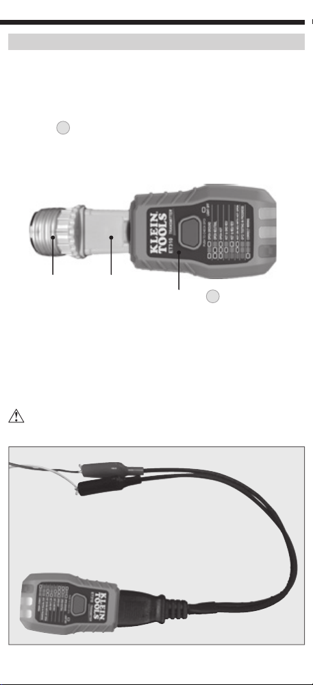
POWER ON/OFF
Press the Power button
3
to power on the receiver
2
, press
and hold the Power button
3
to power off the receiver. A green
indicator
4
illuminated in the Sensing Tip
5
and pulsing
audible beep indicates that the unit is powered ON. The receiver
will automatically power off following 3 minutes of inactivity. The
transmitter
1
is powered by the circuit when inserted into an
energized electrical outlet.
WIRING CONDITION
Prior to using this tester, always verify proper operation by
testing the transmitter on a known energized and correctly wired
electrical outlet.
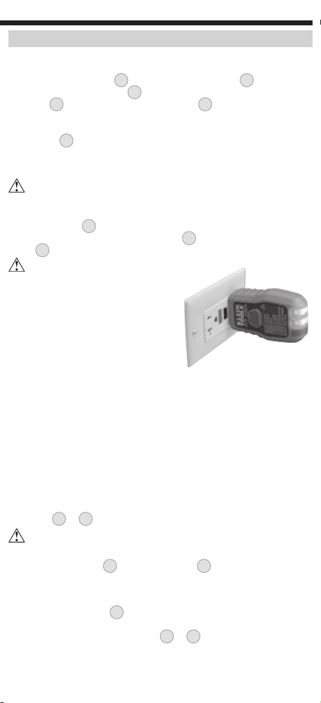
Insert transmitter
1
into the electrical outlet being tested and compare
the illuminated wiring condition indicators
6
with the wiring condition
codes
7
printed on the transmitter (FIG. 1).
If the tester indicates that the
outlet is not wired correctly, consult
a qualied electrician.
NOTE: Conditions NOT indicated
include but are not limited to quality of
ground, multiple hot wires, reversal of
neutral and ground conductors, dual
open ground and neutral, and other
combinations of defects.
NOTE: All appliances or equipment on the circuit being tested should
be unplugged to help reduce the possibility of erroneous readings.
GFCI TEST
NOTE: Check the GFCI device’s user manual for information on how
the specific device operates prior to using this tester.
NOTE: All appliances or equipment on the circuit being tested should
be unplugged to help reduce the possibility of erroneous readings.
NOTE: Not designed for testing 30mA ground-fault devices.
Insert the transmitter into the electrical outlet and note the wiring
condition
6
&
7
.
If the tester indicates that the outlet is not wired correctly, DO
NOT attempt to test the GFCI device. Consult a qualied electrician.
Press the GFCI button
8
on the transmitter
1
to test the GFCI device .
Following the test:
• If the GFCI device tripped, de-energizing the circuit, the wiring
condition indicators
6
will all be off (Open Hot). Reset the GFCI
device by pressing its reset button. After reset, the transmitter
should indicate Correctly Wired
6
&
7
. The GFCI device appears
to be functioning correctly.
• If the circuit remains Energized, the GFCI device didn’t trip, indicating
that it may be incorrectly wired, may not be installed correctly, or
may not be functioning correctly. Consult a qualified electrician.
ENGLISH
WARNINGS
To ensure safe operation and service of the meter, follow these
instructions. Failure to observe these warnings can result in
severe injury or death.
• Failure to follow instructions could result in death or serious injury.
• Prior to use, always verify tester operation by testing on a known live
and correctly wired electrical outlet.
• DO NOT use if the tester appears damaged in any way.
• The tester is intended for indoor use only.
• The tester is designed for use with 120V AC electrical systems. DO
NOT connect to higher voltage electrical supplies.
• Other equipment or devices attached to the circuit being tested could
interfere with the tester, clear the circuit before testing.
• This tester only detects common wiring problems. Always consult a
qualified electrician to resolve wiring problems.
• If using accessories to connect to bare wires ensure that the circuit
is not energized before inspecting, applying, or removing the
transmitter.
• Exercise extreme caution around energized, bare wires, especially
when working in or around an open breaker panel.