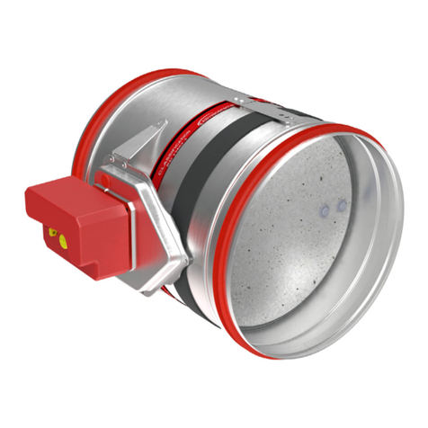
klimaoprema FDC User manual

Gradna 78A, 10430 Samobor, Croatia
+385 (0)1 33 62 513
www.klimaoprema.com
Projektiranje, proizvodnja i održavanje opreme za klimatizaciju, ventilaciju i čiste prostore.
Design, production and service of Ventilation, Air-Conditioning and Cleanroom equipment.
Product manual
Gradna 78A, 10430 Samobor, Croatia
+385 (0)1 33 62 513
www.klimaoprema.com
Projektiranje, proizvodnja i održavanje opreme za klimatizaciju, ventilaciju i čiste prostore.
Design, production and service of Ventilation, Air-Conditioning and Cleanroom equipment.
Fire protection
FDC
Fire damper
Product manual
Version 2.4.6
Issue Date: 25.02.2022.
Design, Herstellung und Wartung von Anlagen für die Klimaanlage, Lüftung und Reinräume.
Design, production and service of Ventilation, Air-Conditioning and Cleanroom equipment.
Brandschutz
FDC
Brandschutzklappe
Produktkatalog
Version 2.4.6
Ausgabedatum: 25.02.2022
Gradna 78A, 10430 Samobor, Kroatien
+385 (0)1 33 62 513

2
PRODUCT OVERVIEW
DIMENSIONS
INSTALLATIONS
ACTUATORS
COMMUNICATIONS MODULES
ACCESSORIES
REPLACEMENTS
MAINTENANCE AND OPERATION
FIRE DAMPER - FDC
ATEX rated versions of fire dampers can be delivered with
Schischek 24 V / 230 V electric actuators that are rated for
installation in explosive atmosphere areas.
All fire dampers are tested according to the EN 1751 for
airtightness and retain class 2 leakage on the closed damper
blade and class C on the casing air leakage.
1. Galvanized steel casing
2. Fire resistant damper blade
3. Actuator
4. Intumescent joint
5. Connection flanges
6. Thermal fuse
1. Gypsum layers
2. Intumescent strip
3. Cold smoke seal
4. Contact layer
PRODUCT OVERVIEW
Fire dampers FDC are used for prevention of fire spread trough
the ventilation ducts and between fire sections. Fire dampers
consist of steel sheet casing, calcium silicate damper blade,
damper blade mechanism outside of the airflow and a manual,
electromagnetic or electric actuator.
Fire damper casing is made out of galvanized steel sheet. Variants
produced from stainless steel and powder coated steel are also
available. Calcium silicate blade is equipped with brass bearings
and seals made out of polyurethane and elastomer rubber.
Fire dampers FDC25 are produced up to size d315 and have 25
mm thick damper blade. Fire dampers FDC40 are produced in
sizes from d355 till d800 and have 40 mm thick damper blade.
FDC25 fire dampers are equipped with R25 manual mechanism
and FDC40 fire dampers are equipped with R40 manual
mechanism.
Manual spring return mechanism is equipped with thermal fuse
that is triggered automatically when the temperature inside the
duct reaches 72 °C. It can also be activated manually by the
push of the button on the mechanism. Additional equipment for
manual mechanism include end contact switches for damper
position signalling. Electromagnetic actuators feature spring
return mechanism with electromagnet for remote activation.
Additional equipment for electromagnetic mechanism include
end contact switches for damper position signalling. Rearming
of the electromagnetic actuator is manual.
Fire dampers with electric actuators are equipped with Belimo
actuator drives in 24 V or 230 V versions. Activation of fire
dampers equipped with electric drives can be via 72 °C or
95 °C thermal fuse or remotely via control signal. Rearming of
the electric fire damper can also be done remotely via control
signal. All electric actuators are equipped with end switches
for position signalling.
2
1
3
4
5
123
4
6
PRODUCT OVERVIEW
PRODUKTÜBERSICHT
ABMESSUNGEN
INSTALLATION
ANTRIEBE
KOMMUNIKATIONS MODULE
ZUBEHÖR
ERSETZUNGEN
WARTUNG UND BETRIEB
BRANDSCHUTZKLAPPE - FDC
ATEX-zertifizierte Versionen von Brandschutzklappen können mit
Schischek 24 V / 230 V Elektroantrieben geliefert werden, die für
die Installation in explosionsgefährdeten Bereichen zugelassen
sind.
Alle Brandschutzklappen sind nach der EN 1751 auf Luftdichtheit
geprüft und behalten die Leckageklasse 2 am geschlossenen
Klappenblatt und die Klasse C an der Gehäuseluftleckage.
1. Gehäuse aus verzinktem Sthalblech
2. Feuerbeständiges Klappenblatt
3. Antrieb
4. Intumeszierende Verbindung
5. Anschluss flansche
6. Thermische Sicherung
1. Gipsschichten
2. Intumeszierender Streifen
3. Kaltrauchdichtung
4. Liegefläche
PRODUKTÜBERSICHT
Brandschutzkalppenverhindern die AusbereitungvonFeuerdurch
Lüftungskanäle zwischen Brandzonen. Brandschutzklappen
bestehen aus einem zylindrischen Gehäuse, einer
Kalziumsilikatlamelle, einem Absperrmechanismus außerhalb
des Luftstroms und einem manuellen, elektromagnetischen oder
motorischen Antrieb.
Brandschutzklappengehäuse besteht aus verzinktem Stahlblech.
Varianten aus Edelstahl und pulverbesichtetem Stahl sind
ebenfalls erhältlich. Kalziumsilikatklinge ist mit Messinglagernund
Dichtungen aus Polyurethan und Elastomergummi ausgestattet.
Brandschutzklappen FDC25 werden bis zur Größe d315
hergestellt und haben ein 25 mm dickes Klappenblatt.
Brandschutzklappen FDC40 werden in Größen von d355 bis
d800 hergestellt und haben ein 40 mm dickes Klappenblatt.
FDC25-Brandschutzklappen sind mit dem manuellen
Mechanismus R25 und und FDC40 sind mit dem manuellen
Mechanismus R40 ausgestattet
Der manuelle Federrücklaufmechanismus ist mit einer
Thermosicherung ausgestattet, die automatisch ausgelöst
wird, wenn die Temperatur im Inneren des Kanals 72 °C
erreicht. Sie kann auch manuell durch Drücken des Knopfes
am Mechanismus aktiviert werden.
Zubehör zur Zusatzausstattung für manuelle Mechanismen
gehören Endkontaktschalter zur Signalisierung der
Klappenstellung. Elektromagnetische Antriebe verfügen
über einen Federrücklaufmechanismus mit Elektromagnet
zur Fernbetätigung. Zur Zusatzausstattung des
elektromagnetischen Antriebs gehören Endschalter zur
Signalisierung der Klappenstellung. Die Wiedereinschaltung
des elektromagnetischen Antriebs erfolgt manuell.
Brandschutzklappen mit elektrischen Antrieben sind mit
Belimo-Stellantrieben in 24 V- oder 230 V-Ausführung
ausgestattet. Die Ansteuerung von Brandschutzklappen
mit elektrischen Antrieben kann über eine 72 °C oder 95 °C
Thermosicherung oder ferngesteuert über ein Steuersignal
erfolgen. Die Rearmierung der elektrischen Brandschutzklappe
kann ebenfalls über ein Steuersignal aus der Ferne erfolgen.
Alle elektrischen Antriebe sind mit Endschaltern zur
Stellungssignalisierung ausgestattet.
PRODUKTÜBERSICHT

3
PRODUCT OVERVIEW
DIMENSIONS
INSTALLATIONS
ACTUATORS
COMMUNICATIONS MODULES
ACCESSORIES
REPLACEMENTS
MAINTENANCE AND OPERATION
FIRE DAMPER - FDC
TESTS AND
CERTIFICATES
All our dampers are submitted to a number of tests by official
test institutes. Reports of these tests form the basis for the
approvals of our dampers. Fire dampers are also suitable for
installation in buildings with high hygienic demands such as
hospitals, clinics and pharmaceutical areas.
To confirm this, out products are tested by an independent
Institute of Hygiene, based in Gelsenkirchen, Ruhr, and comply
with directives and guidelines in VDI 6022.
FIRE RESISTANCE
CLASSIFICATION
FDC fire resistance is tested according to EN 1366-2 “Fire
resistance tests for service installations- Part 2: Fire dampers”.
Classification of the fire dampers is defined according to EN
13501-3 Fire classification of construction products and
building elements.
Installation in both, vertical and horizontal axis of rotation of the
dampers blade is acceptable (with the axis angle 0 - 360°).
Fire resistance of fire damper depends on classification of walls
or ceilings. It is allowed to install products to walls or ceilings
only according to products Declaration of Performance. Walls
or ceilings with greater fire resistance can also be used. Fire
damper should be installed according to the installation manual
which can be found within this document.
Please consult latest Declaration of Performance:
For more information about certificates, visit our website:
www.klimaoprema.com/fdc
E- Integrity
I- Insulation
120/90/60 - Classification time in minutes
S- Smoke leakage
ve - Damper installed in vertical compartment
ho - Damper installed in horizontal compartment
i↔o- Fire performance criteria are met on both sides
PRODUCT OVERVIEW
PRODUCT OVERVIEW
www.klimaoprema.com/fdc/dop
PRODUKTÜBERSICHT
ABMESSUNGEN
INSTALLATION
ANTRIEBE
KOMMUNIKATIONS MODULE
ZUBEHÖR
ERSETZUNGEN
WARTUNG UND BETRIEB
BRANDSCHUTZKLAPPE - FDC
PRODUKTÜBERSICHT
PRÜFUNGEN UND
ZERTIFIKATE
Alle unsere Klappen werden einer Reihe von Prüfungen durch
offizielle Prüfinstitute unterzogen. Die Berichte über diese
Prüfungen bilden die Grundlage für die Zulassungen unserer
Klappen. Klimaoprema Brandschutzklappen sind auch für den
Einbau in Gebäuden mit hohen hygienischen Anforderungen
wie Krankenhäuser, Kliniken und pharmazeutische Bereiche
geeignet.Um dies zu bestätigen, werden unsere Produkte von
einem unabhängigen Hygieneinstitut mit Sitz in Gelsenkirchen,
Ruhr, geprüft und entsprechen den Richtlinien und Vorgaben
der VDI 6022.
FEUERBESTÄNDIGKEIT
KLASSIFIZIERUNG
Der Feuerwiderstand von FDC wird nach EN 1366-
2 “Feuerwiderstandsprüfungen für betriebstechnische
Anlagen - Teil 2: Brandschutzklappen” geprüft. Die
Klassifizierung der Brandschutzklappen ist nach EN 13501-
3 “Brandschutzklassifizierung von Bauprodukten und
Bauelementen” definiert
Der Einbau ist sowohl in der vertikalen als auch in der
horizontalen Drehachse des Klappenblattes zulässig
(mit dem Achswinkel 0 - 360°). Die Feuerbeständigkeit der
Brandschutzklappe hängt von der Klassifizierung der Wände
oder Decken ab. Der Einbau der Produkte in Wände oder
Decken ist nur gemäß der Leistungserklärung der Produkte
zulässig. Es können auch Wände oder Decken mit höherem
Feuerwiderstand verwendet werden. Die Brandschutzklappe
sollte gemäß der Installationsanleitung installiert werden, die
Sie in diesem Dokument finden.
Bitte beachten Sie die aktuelle Leistungserklärung:
Für weitere Informationen über Zertifikate besuchen Sie
unsere Website:
E - Integrität
I- Isolierung
120/90/60 - Klassifizierungszeit in Minuten
S- Rauchleckage
ve - Installation mit vertikaler Drehachse
ho - Installation mit horizontaler Drehachse
i↔o- Brandverhaltenskriterien werden auf beiden Seiten
erfüllt

4
PRODUCT OVERVIEW
DIMENSIONS
INSTALLATIONS
ACTUATORS
COMMUNICATIONS MODULES
ACCESSORIES
REPLACEMENTS
MAINTENANCE AND OPERATION
FIRE DAMPER - FDC
Pressure drop values are described with the “Zeta” values for
each size. The exact pressure drop in [Pa] is calculated using
the following formula:
Product label
1 - Casing air leakage classification
2 - Serial number
3 - Production date
4 - Type
5 - Dimension of the fire damper
6 - Mechanism type
7 - Nominal voltage
8 - Signalisation (end contacts)
9 - IP protection
10 - Free space
11 - Thermal fuse temperature
12 - Number of the European standard and
year of its publication
13 - Declaration of performance
14 - Classification according to EN 13501-3
15 - Barcode
16 - CE mark
TECHNICAL DATA
Fire damper casing is manufactured from galvanized
steel sheet, but on demand can be produced out of:
• Galvanized steel and powder coated
• Stainless steel EN 1.4301/EN 1.4404
(AISI 304/316L)
• Stainless steel EN 1.4301/EN 1.4404
(AISI 304/316L) and powder coated
Fire damper for areas with potentially explosive
atmospheres are also available
2
3
4
5
6
1
7
15
11
9
10
12
13
14
Nominal sizes FDC 100 - 800 [mm]
Casing length 380 mm
Temperature range -20 °C ... 50 °C
Release temperature 72 °C (standard) or 95 °C
(optional with electric actuator)
Volume flow rate range up to 21700 m³/h
Differential pressure range up to 1000 Pa
Casing air leakage Class C, EN 1751
Closed blade air leakage Class 3, EN 1751
Upstream velocity < 12 m/s
EC conformity EN 13501-3, EN 1366-2,
EN 15650, EN 1751,
CPR no.305/2011
Declaration of
performance
DoP 711/2020_12
FDC25 d100 d125 d160 d200 d250 d315
ζ1,759 0,852 0,545 0,445 0,340 0,293
FDC40 d355 d400 d450 d500 d560 d630 d710 d800
ζ0,428 0,389 0,344 0,325 0,312 0,232 0,206 0,179
Δp [Pa]= ζ * v² * 0,6
Product specifications Pressure drop tables
where ζis Zeta value from the tables below, v is airflow veloc-
ity in [m/s]
Diameter
[mm]
Cross section
[dm²]
Net area
[dm²]
FDC25
100 0,74 0,50
125 1,17 0,87
160 1,93 1,55
200 3,05 2,56
250 4,79 4,18
315 7,64 6,87
FDC40
355 9,73 8,33
400 12,37 10,79
450 15,69 13,91
500 19,39 17,41
630 30,86 28,36
710 39,24 36,42
800 49,86 46,68
Dimensional range
CLASS C EN1751
SERIAL NUMBER: 28502800400001
PRODUCTION DATE: 01.01.2020
TYPE: FDC40-d500-M24-S
DIMENSION: d500
ACT. MECHANISM: M24
NOMINAL VOLTAGE: AC/DC 24V
SIGNALISATION: Yes
LOCATION:
IP PROTECTION: IP54
FRE SPACE (dm2):
THERMAL FUSE: 72˚C
1812
17
1812-CPR-1161
PRODUCT MUST BE INSTALLED BY INSTRUCTIONS SUPPLIED BY THE MANUFACTURER
28502800400001
8
16
FREE SPACE (dm2):
PRODUCT OVERVIEW
PRODUKTÜBERSICHT
ABMESSUNGEN
INSTALLATION
ANTRIEBE
KOMMUNIKATIONS MODULE
ZUBEHÖR
ERSETZUNGEN
WARTUNG UND BETRIEB
BRANDSCHUTZKLAPPE - FDC
PRODUKTÜBERSICHT
Druckabfallwerte werden mit den “Zeta”-Werten beschrieben
für jede Größe angegeben. Der genaue Druckabfall in [Pa]
wird nach folgender Formel berechnet:
Produktetikett
1 - Klassifizierung der Gehäuseluftleckage
2 - Seriennummer
3 - Produktionsdatum
4 - Typ
5 - Abmessung der Brandschutzklappe
6 - Mechanismustyp
7 - Nennspannung
8 - Signalisierung (Endkontakte)
9 - IP Schutz
10 - Freiraum
11 - Temperatur der Thermosicherung
12 - Nummer der Europäischen Norm und Jahr der
Veröffentlichung
13 - Leistungserklärung
14 - Klassifizierung nach EN 13501-3
15 - Barcode
16 - CE Marke
TECHNISCHE
DATEN
Brandschutzklappengehäuse werden aus
verzinktem Stahlblech gefertigt, können aber auf
Wunsch auch aus anderen Materialien hergestellt
werden:
• Verzinkter Stahl und pulverbeschichtet
• Edelstahl EN 1.4301/EN 1.4404
(AISI 304/316L)
• Edelstahl EN 1.4301/EN 1.4404 (AISI 304/316L)
und pulverbeschichtet
Brandschutzklappen für explosionsgefährdete
Bereiche sind ebenfalls erhältlich
Nenngrößen FDC 100 - 800 mm
Gehäuselänge 380 mm
Temperaturbereich -20 °C ... 50 °C
Freigabetemperatur 72 °C (standard) or 95 °C (optional mit
elektrischem Stellantrieb)
Volumenstrombereich bis zu 21700 m³/h
Differenzdruckbereich bis zu 1000 Pa
Gehäuse-Luftleckage Class C, EN 1751
Geschlossene Baldenluftleitung Class 2, EN 1751
Anströmgeschwindigkeit < 12 m/s
EC-Konformität EN 13501-3, EN 1366-2, EN 15650,
EN 1751,
CPR no.305/2011
Leistungserklärung DoP 711/2020_12_EN
FDC25 d100 d125 d160 d200 d250 d315
ζ1,759 0,852 0,545 0,445 0,340 0,293
FDC40 d355 d400 d450 d500 d560 d630 d710 d800
ζ0,428 0,389 0,344 0,325 0,312 0,232 0,206 0,179
Δp [Pa]= ζ * v² * 0,6
Produktspezifikationen Druckverlust Tabelle
wobei ζder Zeta-Wert aus den untenstehenden Tabellen ist,
v die Luftstromgeschwindigkeit in [m/s]
Durch-
messer[mm]
Querschnitt
[dm²]
Netto-Fläche
[dm²]
FDC25
100 0,74 0,50
125 1,17 0,87
160 1,93 1,55
200 3,05 2,56
250 4,79 4,18
315 7,64 6,87
FDC40
355 9,73 8,33
400 12,37 10,79
450 15,69 13,91
500 19,39 17,41
630 30,86 28,36
710 39,24 36,42
800 49,86 46,68
Abmessungsbereich

5
PRODUCT OVERVIEW
DIMENSIONS
INSTALLATIONS
ACTUATORS
COMMUNICATIONS MODULES
ACCESSORIES
REPLACEMENTS
MAINTENANCE AND OPERATION
FIRE DAMPER - FDC
MODELS
Casings
Actuators
R (R-S)
Manual operating mechanism, optionally with end switches (R-S). In case
of fire, the fire damper closes automatically. Damper closing can be initiated
either by thermal fuse melting, or by manual activation on the operating
mechanism. Upon closure, damper blade is locked in closed position and
can only be opened manually. Thermal fuse melting point is 72 °C.
EMS-S
Electromagnetic operating mechanism, comes with end switches as
standard. In case of fire, the fire damper closes automatically. Damper
closing can be initiated either by thermal fuse melting or remotely by
triggering the electromagnet. Electromagnet is constantly under power and
activates closing of the damper blade in case the power cuts out. Upon
closure, damper blade is locked in closed position and can only be opened
manually. Thermal fuse melting point is 72 °C.
M230-S
Belimo 230 V electro motor operating mechanism, comes with integrated
end switches. In case of fire, the fire damper closes automatically.
Damper closing can be initiated either by thermoelectric release device or
remotely by triggering the electro motor. Upon closure, damper blade is
locked in closed position and can be opened by sending a signal to electro
motor. Standard thermoelectric release point is 72 °C, optional 95 °C.
M24-S
Belimo 24 V electro motor operating mechanism, comes with integrated
end switches. In case of fire, the fire damper closes automatically.
Damper closing can be initiated either by thermoelectric release device
or remotely by triggering the electro motor. Upon closure, damper blade
is locked in closed position and can be opened by sending a signal to
electro motor. Standard thermoelectric release point is 72 °C,
optional 95 °C.
M24-S-ST
Belimo 24 V electro motor operating mechanism, comes with integrated
end switches. In case of fire, the fire damper closes automatically.
Damper closing can be initiated either by thermoelectric release device
or remotely by triggering the electro motor. Upon closure, damper blade
is locked in closed position and can be opened by sending a signal to
electro motor. Standard thermoelectric release point is 72 °C,
optional 95 °C. Actuator is additionally equipped with connection plug for
easy connection with power supply and communication modules.
EX
ATEX rated fire dampers are equipped with Schischek ExMax-5.10-BF
actuators, ExPro-TT thermal switches and ExBox-BF plenum boxes.
Optional casing can be produced in AISI316L stainless steel.
Ordering key
FDC25
Cylindrical fire damper with 25 mm damper blade and
fire classification up to EI120S. Sizes range from d100
till d315.
FDC40
Cylindrical fire damper with 40 mm damper blade and
fire classification up to EI120S. Sizes range from d355
till d800.
FDC25 - APP
Cylindrical fire damper with integrated Applique
installation frame with 25 mm damper blade and fire
classification up to EI90S.
Sizes range from d100 till d315.
FDC25 - MF1/MF2
Cylindrical fire damper with integrated MF1 installation
frame with 25 mm damper blade and fire classification
up to EI60S. Sizes range from d100 till d315.
FDC40 - MF2
Fire damper with integrated MF2 installation frame
with 40 mm damper blade and fire classification up to
EI90S. Sizes range from d355 till d800.
(1) Damper type (2) Dimension (3) Mechanism type (4) Mounted accessories
FDC25 - d250 - M230-S - IH
(1)
(2)
FDC25 - d100 to d315
FDC40 - d355 to d800
FDC25-APP - d100 to d315
FDC25-MF1 - d100 to d315
FDC25-MF2 - d100 to d315
FDC40-MF2 - d355 to d800
Damper diameter
d100 till d800
(3)
(4)
R- manual drive
R-S - manual drive with limit switches
M230-S - electric actuator AC/DC 230 V
M24-S - electric actuator AC/DC 24 V
M24-S-ST - electric actuator AC/DC 24 V with
connection plug
EMS-S - electromagnetic drive
EX - electric actuator Schischek ExMax -5.10-BF
+ExPro-TT+ExBox-BF
IH - inspection hatch
PRODUCT OVERVIEW
PRODUKTÜBERSICHT
ABMESSUNGEN
INSTALLATION
ANTRIEBE
KOMMUNIKATIONS MODULE
ZUBEHÖR
ERSETZUNGEN
WARTUNG UND BETRIEB
BRANDSCHUTZKLAPPE - FDC
PRODUKTÜBERSICHT
MODELLE
Gehäuse
Antriebe
R (R-S)
Manuelle Betätigungseinrichtung, optional mit Endschaltern (R-S). Im
Brandfall schließt die Brandschutzklappe automatisch. Das Schließen
der Klappe kann entweder durch Schmelzen der Thermosicherung oder
durch manuelle Betätigung am Stellantrieb ausgelöst werden. Nach dem
Schließen ist das Klappenblatt in geschlossener Stellung verriegelt und kann
nur manuell geöffnet werden. Der Schmelzpunkt der Thermosicherung
beträgt 72 °C.
EMS-S
Elektromagnetische Betätigungsmechanik, serienmäßig mit Endschaltern.
Im Brandfall schließt die Brandschutzklappe automatisch. Das Schließen
der Klappe kann entweder durch das Schmelzen der Thermosicherung oder
aus der Ferne durch Auslösen des Elektromagneten ausgelöst werden. Der
Elektromagnet steht ständig unter Spannung und aktiviert das Schließen
des Klappenblattes bei Stromunterbrechung. Nach dem Schließen ist das
Klappenblatt in der geschlossenen Position verriegelt und kann nur manuell
geöffnet werden. Der Schmelzpunkt der Thermosicherung liegt bei 72 °C.
M230-S
Belimo 230 V elektromotorischer Antrieb, mit integrierten Endschaltern.
Im Brandfall schließt die Brandschutzklappe automatisch. Das Schließen
der Klappe kann entweder durch die thermoelektrische Auslöseeinrichtung
oder durch Ansteuerung des Elektromotors aus der Ferne ausgelöst
werden. Nach dem Schließen ist das Klappenblatt in der geschlossenen
Position verriegelt und kann durch ein Signal an den Elektromotor geöffnet
werden. Der thermoelektrische Auslösepunkt beträgt standardmäßig 72
°C, optional 95 °C.
M24-S
Das Schließen der Klappe kann entweder durch die thermoelektrischeectro
end switches. In case of fire, the fire damper closes automatically. Nach
dem Schließen ist das Klappenblatt in der geschlossenen Position
verriegelt kann durch ein Signal an den Elektromotor geöffnet werden.
Der thermoelektrische Auslösepunkt beträgt standardmäßig 72 °C,
optional 95 °C.
M24-S-ST
Belimo 24-V-Elektromotorantrieb, mit integrierten Endschaltern. Im
Brandfall schließt die Brandschutzklappe automatisch.
Das Schließen der Klappe kann entweder durch die thermoelektrische
Auslöseeinrichtung oder durch Ansteuerung des Elektromotors aus der
Ferne ausgelöst werden. Nach dem Schließen ist das Klappenblatt in
der geschlossenen Position verriegelt und kann durch ein Signal an den
Elektromotor geöffnet werden. Standardmäßig liegt der thermoelektrische
Auslösepunkt bei 72 °C, optional 95 °C. Der Stellantrieb ist zusätzlich mit
einem Anschlussstecker zur einfachen Verbindung mit Stromversorgungs-
und Kommunikationsmodulen ausgestattet.
EX
ATEX-zertifizierte Brandschutzklappen sind mit Schischek
ExMax-Antrieben, Exbox-TT Thermoschaltern und ExBox-
Anschlusskästen ausgestattet. Optional kann das Gehäuse in Edelstahl
AISI316L gefertigt werden.
Bestellschlüssel
FDC25
Zylindrische Brandschutzklappe mit 25 mm
Klappenblatt und Brandklassifizierung bis EI120S.
Größenbereich von d100 bis d315.
FDC40
Zylindrische Brandschutzklappe mit 40 mm
Klappenblatt und Brandklassifizierung bis EI120S. Die
Größen reichen von d355 bis d800.
FDC25-APP
Zylindrische Brandschutzklappe mit integriertem
Einbaurahmen Applique mit 25 mm Klappenblatt und
Brandklassifizierung bis EI90S.
Größenbereich von d100 bis d315.
FDC25-MF1/MF2
Zylindrische Brandschutzklappe mit integriertem
Einbaurahmen MF1/MF2 mit 25 mm Klappenblatt und
Brandklassifizierung bis EI60S. Die Größen reichen von
d100 bis d315.
FDC40-MF2
Brandschutzklappe mit integriertem Einbaurahmen
MF2 mit 40 mm Klappenblatt und Brandklassifizierung
bis EI90S. Größenbereich von d355 bis d800.
(1) Klappenart (2) Abmessung (3) Mechanismus Typ (4) Montiertes Zubehör
FDC25 - d250 - M230-S - IH
(1)
(2)
FDC25 - d100 bis d315
FDC40 - d355 bis d800
FDC25-APP - d100 bis d315
FDC25-MF1 - d100 bis d315
FDC25-MF2 - d100 bis d315
FDC40-MF2 - d355 bis d800
Klappen-Durchmesser
d100 bis d800
(3)
(4)
R- Handantrieb
R-S - Handantrieb mit Endschaltern
M230-S - elektrischer Antrieb AC/DC 230 V
M24-S - elektrischer Antrieb AC/DC 24 V
M24-S-ST - elektrischer Antrieb AC/DC24 V mit
Anschlussstecker
EMS-S - elektromagnetischer Antrieb
EX - ATEX klassifiziert Schischek 230/24 V
elektrischer Stellantrieb
IH - Inspektionsöffnung
6
PRODUCT OVERVIEW
DIMENSIONS
INSTALLATIONS
ACTUATORS
COMMUNICATIONS MODULES
ACCESSORIES
REPLACEMENTS
MAINTENANCE AND OPERATION
FIRE DAMPER - FDC
FDC25-R FDC40-R
Ød [mm] 100 125 160 200 250 315 355 400 450 500 560 630 710 800
Weight [kg] 3,8 4,2 4,7 5,4 6,3 7,7 11,9 13,5 15,4 17,5 20,4 23,6 27,7 33,7
K [mm] 120 128 140 155 176 204 221 242 265 289 317 351 389 433
FDC25/ FDC40 - R
(manual mechanism)
• Automatic closure when the temperature
in the duct exceeds 72 °C
• Manual rearming with handle
• Manual unlocking possible for periodical test
of fire damper
• Optional with end position switches (-R-S)
• FDC25 fire dampers are equipped with R25
manual mechanism
• FDC40 fire dampers are equipped with R40
manual mechanism
FDC25-R25 (up to d315) FDC40-R40 (d355 up to d800)
DIMENSIONS
380
F FX
d
A
C
E
D
X F
380
AC
F
d/2+12
d/2+22
E
D
d/2+22 d/2+12
K
K
Product
A
[mm]
C
[mm]
D
[mm]
E
[mm]
F
[mm]
FDC 25 55 150 105 150 42
FDC 40 55 200 105 200 42
Length of damper blade outside of casing
(X dimension on front side):
X=(Ød/2)-110 [mm]
*If the damper is larger than Ø540, use formula
(Y dimension on back side):
Y=(Ød/2)-270 [mm]
*K - Dimension of the minimum installation opening
173
215
PRODUKTÜBERSICHT
ABMESSUNGEN
INSTALLATION
ANTRIEBE
KOMMUNIKATIONS MODULE
ZUBEHÖR
ERSETZUNGEN
WARTUNG UND BETRIEB
BRANDSCHUTZKLAPPE - FDC
ABMESSUNGEN
FDC25/ FDC40-R
(handantrieb)
• Automatische Schließung, wenn die Temperatur
im Kanal 72 °C überschreitet
• Manuelle Nachrüstung mit Griff
• Manuelle Entriegelung möglich für die regelmäßige
Prüfung der Brandschutzklappe
• Optional mit Endlagenschaltern (-R-S)
• FDC25 Brandschutzklappen sind mit dem
Handantrieb R25 ausgestattet
• FDC40 Brandschutzklappen sind mit dem
Handantrieb R40 ausgestattet
FDC25-R25 (bis zu d315) FDC40-R40 (d355 bis zu d800)
FDC25-R FDC40-R
Ød [mm] 100 125 160 200 250 315 355 400 450 500 560 630 710 800
Gewicht [kg] 3,8 4,2 4,7 5,4 6,3 7,7 11,9 13,5 15,4 17,5 20,4 23,6 27,7 33,7
K [mm] 120 128 140 155 176 204 221 242 265 289 317 351 389 433
*K - Maß der minimalen Einbauöffnung
Produkt
A
[mm]
C
[mm]
D
[mm]
E
[mm]
F
[mm]
FDC 25 55 150 105 150 42
FDC 40 55 200 105 200 42
Länge des Klappenblattes außerhalb des Gehäuses
(Y-Maß auf der Vorderseite)
Y=(Ød/2)-110 [mm]
* Wenn der Dämpfer größer als Ø540 ist, verwenden Sie
die Formel (X-Maß auf der Rückseite)
X=(Ød/2)-270 [mm]

7
PRODUCT OVERVIEW
DIMENSIONS
INSTALLATIONS
ACTUATORS
COMMUNICATIONS MODULES
ACCESSORIES
REPLACEMENTS
MAINTENANCE AND OPERATION
FIRE DAMPER - FDC
FDC25/ FDC40 - EMS
(solenoid actuator)
• Electromagnetic actuator with integrated limit
switches and thermal fuse release mechanism
(72 °C)
• Manual rearming with handle
• Remote closing with electromagnetic actuator
• Manual closing possible
• EMS - solenoid actuator is constantly under power.
Actuating mechanism is tripped when the power is
interrupted, or thermal fuse is melted.
DIMENSIONS
380
F FX
d
A
C
E
D
d/2+22 d/2+12
K
Product
A
[mm]
C
[mm]
D
[mm]
E
[mm]
F
[mm]
FDC 25 55 150 105 150 42
FDC 40 55 200 105 200 42
Length of damper blade outside of casing
(X dimension on front side):
X=(Ød/2)-110 [mm]
*If the damper is larger than Ø540, use formula
(Y dimension on back side):
Y=(Ød/2)-270 [mm]
FDC25-EMS FDC40-EMS
Ød [mm] 100 125 160 200 250 315 355 400 450 500 560 630 710 800
Weight [kg] 5,3 5,7 6,2 6,9 7,8 9,2 12,2 13,8 15,7 17,8 20,7 23,9 28 34
K [mm] 120 128 140 155 176 204 221 242 265 289 317 351 389 433
*K - Dimension of the minimum installation opening
215
PRODUKTÜBERSICHT
ABMESSUNGEN
INSTALLATION
ANTRIEBE
KOMMUNIKATIONS MODULE
ZUBEHÖR
ERSETZUNGEN
WARTUNG UND BETRIEB
BRANDSCHUTZKLAPPE - FDC
ABMESSUNGEN
FDC25/ FDC40-EMS
(Magnetantrieb)
• Federrücklaufantrieb mit integrierten Endschaltern
und thermoelektrischem Auslösemechanismus
(72 °C)
• Manuelle Aufrüstung mit Griff
• Mögliches Schließen mit Magnet
• Manuelles Schließen möglich
• EMS-Magnetantrieb steht ständig unter Spannung.
Der Stellantrieb wird ausgelöst, wenn die
Stromversorgung unterbrochen wird oder die
Thermosicherung geschmolzen ist.
FDC25-EMS FDC40-EMS
Ød [mm] 100 125 160 200 250 315 355 400 450 500 560 630 710 800
Gewicht [kg] 5,3 5,7 6,2 6,9 7,8 9,2 12,2 13,8 15,7 17,8 20,7 23,9 28 34
K [mm] 120 128 140 155 176 204 221 242 265 289 317 351 389 433
*K - Maß der minimalen Einbauöffnung
Länge des Klappenblattes außerhalb des Gehäuses
(Y-Maß auf der Vorderseite)
Y=(Ød/2)-110 [mm]
* Wenn der Dämpfer größer als Ø540 ist, verwenden Sie
die Formel (X-Maß auf der Rückseite)
X=(Ød/2)-270 [mm]
Produkt
A
[mm]
C
[mm]
D
[mm]
E
[mm]
F
[mm]
FDC 25 55 150 105 150 42
FDC 40 55 200 105 200 42

8
PRODUCT OVERVIEW
DIMENSIONS
INSTALLATIONS
ACTUATORS
COMMUNICATIONS MODULES
ACCESSORIES
REPLACEMENTS
MAINTENANCE AND OPERATION
FIRE DAMPER - FDC
FDC25/FDC40 - M
(electric actuator)
• Thermoelectric release device (72 °C) with
electric actuator and return spring
• Integrated end switches
• Fully automatic operation
• Optional 95 °C thermoelectric release device for
warm air installations
Product
A
[mm]
C
[mm]
D
[mm]
E
[mm]
BFL (M) 25 200 90 120
BFN (M) 25 225 100 120
BF (M)* 50 250 100 120
Product
F
[mm]
FDC 25 42
FDC 40 42
DIMENSIONS
F F
380
d
X D
d/2+12
d/2+12
A
E
C
A
K
Length of damper blade outside of casing
(X dimension on front side):
X=(Ød/2)-110 [mm]
*If the damper is larger than Ø540, use formula
(Y dimension on back side):
Y=(Ød/2)-270 [mm]
*K - Dimension of the minimum installation opening
FDC25-M FDC40-M
Ød [mm] 100 125 160 200 250 315 355 400 450 500 560 630 710 800
Weight [kg] 4,5 4,9 5,4 6,1 7 8,4 11,7 13,3 15,2 17,3 20,2 23,4 29,1 35,1
Actuator type BFL BFL BFL BFL BFL BFL BFN BFN BFN BFN BFN BFN BF BF
K [mm] 120 128 140 155 176 204 221 242 265 289 317 351 389 433
215
PRODUKTÜBERSICHT
ABMESSUNGEN
INSTALLATION
ANTRIEBE
KOMMUNIKATIONS MODULE
ZUBEHÖR
ERSETZUNGEN
WARTUNG UND BETRIEB
BRANDSCHUTZKLAPPE - FDC
ABMESSUNGEN
FDC25 / FDC40-M
(elektrischer
Stellantrieb)
• Thermoelektrische Aktivierung (72 ° C), mit
elektrischem Antrieb und die Rückstellfeder
• Integrated end switches
• Fully automatic operation
• Optional 95 °C thermoelektrische Auslöseein-
richtung für Warmluftanlagen
Produkt
A
[mm]
C
[mm]
D
[mm]
E
[mm]
BFL (M) 25 200 90 120
BFN (M) 25 225 100 120
BF (M)* 50 250 100 120
Länge des Klappenblattes außerhalb des Gehäuses
(Y-Maß auf der Vorderseite)
Y=(Ød/2)-110 [mm]
* Wenn der Dämpfer größer als Ø540 ist, verwenden Sie
die Formel (X-Maß auf der Rückseite)
X=(Ød/2)-270 [mm]
FDC25-M FDC40-M
Ød [mm] 100 125 160 200 250 315 355 400 450 500 560 630 710 800
Gewicht [kg] 4,5 4,9 5,4 6,1 7 8,4 11,7 13,3 15,2 17,3 20,2 23,4 29,1 35,1
Mechanismus Typ BFL BFL BFL BFL BFL BFL BFN BFN BFN BFN BFN BFN BF BF
K [mm] 120 128 140 155 176 204 221 242 265 289 317 351 389 433
*K - Maß der minimalen Einbauöffnung
Produkt
F
[mm]
FDC 25 42
FDC 40 42

9
PRODUCT OVERVIEW
DIMENSIONS
INSTALLATIONS
ACTUATORS
COMMUNICATIONS MODULES
ACCESSORIES
REPLACEMENTS
MAINTENANCE AND OPERATION
FIRE DAMPER - FDC
FDC25/FDC40 - EX
(electric actuator)
• Thermoelectric release device (72 °C) with
electric actuator and return spring
• Integrated end switches
• Fully automatic operation
• The EX version of the damper comes with:
1) Safety temperature trigger Schischek
ExPro-TT
2) Electric actuator Schischek ExMax-5.10-BF
3) Terminal box Schischek ExBox-BF
For more information see page 43.
d/2+12
220
95
125
44
44
320
380
F
F
80
d
Y
d/2+22
Model
F
[mm]
FDC 25 42
FDC 40 42
Ex classification of product:
II 2G Ex h IIC T6 Gb
II 2D Ex h IIIC T80°C Db
For more information about Ex classification, visit
website: ATEX classification!
Type Examination Certificate Number: FIDI 21 ATEX
D059. Equipment complies with the essential health
and safety requirements relating to the design and
construction of equipment intended to use in potentially
explosive atmospheres given in annex VIII of the directive
ATEX 2014/34/EU.
Please consult latest Declaration of conformity on our
website:
www.klimaoprema.com/Doc
1
2
3
DIMENSIONS
X
K
Length of damper blade outside of casing
(X dimension on front side):
X=(Ød/2)-110 [mm]
*If the damper is larger than Ø540, use formula
(Y dimension on back side):
Y=(Ød/2)-270 [mm]
FDC25-EX FDC40-EX
Ød [mm] 100 125 160 200 250 315 355 400 450 500 560 630 710 800
Weight [kg] 7,9 8,3 8,8 9,5 10,4 11,8 14,8 16,4 18,3 20,4 23,1 26,5 30,6 36,6
Actuator type ATEX rated Schischek 24/230 V electric actuator+ExPro-TT+ExBox-BF
K [mm] 120 128 140 155 176 204 221 242 265 289 317 351 389 433
*K - Dimension of the minimum installation opening
PRODUKTÜBERSICHT
ABMESSUNGEN
INSTALLATION
ANTRIEBE
KOMMUNIKATIONS MODULE
ZUBEHÖR
ERSETZUNGEN
WARTUNG UND BETRIEB
BRANDSCHUTZKLAPPE - FDC
ABMESSUNGEN
FD25/FD40 - EX
(electric actuator)
• Thermoelektrische Auslösevorrichtung (72 °C)
mit elektrischem Antrieb und Rückstellfeder
• Integrierte Endschalter
• Vollautomatischer Betrieb
• Die EX-Version des Dämpfers wird geliefert mit:
1) Sicherheitstemperaturauslöser Schischek
ExPro-TT
2) Elektrischer Stellantrieb Schischek ExMax-
5.10-BF
3) Anschlusskasten Schischek ExBox-BF
Weitere Informationen finden Sie auf Seite 43.
Ex classification of product:
Weitere Informationen zur Ex-Klassifizierung finden Sie
auf der Website: ATEX classification
Nummer der Baumusterprüfbescheinigung: FIDI 21
ATEX D059. Das Gerät erfüllt die grundlegenden
Gesundheits- und Sicherheitsanforderungen in Bezug
auf die Konstruktion und den Bau von Geräten, die
für den Einsatz in explosionsgefährdeten Bereichen
vorgesehen sind, die in Anhang VIII der Richtlinie ATEX
2014/34/EU angegeben sind.
Bitte konsultieren Sie die aktuelle Konformitätserklärung
auf unserer Website:
www.klimaoprema.com/FD-EX Doc
Länge des Klappenblattes außerhalb des Gehäuses
(Y-Maß auf der Vorderseite)
Y=(Ød/2)-110 [mm]
* Wenn der Dämpfer größer als Ø540 ist, verwenden Sie
die Formel (X-Maß auf der Rückseite)
X=(Ød/2)-270 [mm]
Model
F
[mm]
FDC 25 42
FDC 40 42

10
PRODUCT OVERVIEW
DIMENSIONS
INSTALLATIONS
ACTUATORS
COMMUNICATIONS MODULES
ACCESSORIES
REPLACEMENTS
MAINTENANCE AND OPERATION
FIRE DAMPER - FDC
FDC25 - APP
Applique installation
frame
• Applique kit is an installation subframe for quick
and easy installation in rigid and flexible walls
• Made out of calcium silicate boards
• Quick wall mounting with screws
• Factory assembled to the fire damper
FDC25-APP-R FDC25-APP-EMS FDC25-APP-M
Ød [mm] 100 125 160 200 250 315 100 125 160 200 250 315 100 125 160 200 250 315
Weight [kg] 6,2 6,7 7,8 8,5 10,1 12,3 7,7 8,2 9,3 10 11,6 13,8 6,9 7,4 8,5 9,2 10,8 13
FDC25-APP-EMS
FDC25-APP-R FDC25-APP-M
Damper diameter
Ød[mm] Applique frame diameter
Ød + A [mm]
100 Ød +105 mm
125 - 160 Ød + 95 mm
200 - 315 Ød + 80 mm
Product
F
[mm]
FDC 25 42
FDC 40 42
DIMENSIONS
d/2+80
d/2+124
d
45 100 F
380
d/2+80
d/2+124
d
45 100 F
380
d+A
Ød+160
380
10045
d
d+A
F
380
10045
d
d+A
F
45 100
380
F
d
d+A
d/2+94
d/2+80
PRODUKTÜBERSICHT
ABMESSUNGEN
INSTALLATION
ANTRIEBE
KOMMUNIKATIONS MODULE
ZUBEHÖR
ERSETZUNGEN
WARTUNG UND BETRIEB
BRANDSCHUTZKLAPPE - FDC
ABMESSUNGEN
FDC25-APP
Applique
Einbaurahmen
• Applique ist ein Einbaurahmen für den schnellen
und einfachen Einbau in starre und flexible Wände
• Hergestellt aus Kalziumsilikatplatten
• Schnelle Wandmontage mit Schrauben
• Werkseitig an der Brandschutzklappe montiert
FDC25-APP-R FDC25-APP-EMS FDC25-APP-M
Ød [mm] 100 125 160 200 250 315 100 125 160 200 250 315 100 125 160 200 250 315
Gewicht [kg] 6,2 6,7 7,8 8,5 10,1 12,3 7,7 8,2 9,3 10 11,6 13,8 6,9 7,4 8,5 9,2 10,8 13
Durchmesser
Dämpfer Ød[mm]
Applique
Rahmendurchmesser
Ød + A [mm]
100 Ød +105 mm
125 - 160 Ød + 95 mm
200 - 315 Ød + 80 mm

11
PRODUCT OVERVIEW
DIMENSIONS
INSTALLATIONS
ACTUATORS
COMMUNICATIONS MODULES
ACCESSORIES
REPLACEMENTS
MAINTENANCE AND OPERATION
FIRE DAMPER - FDC
FDC25 - MF1
MF1 installation
frame
• MF1 is an installation frame for quick and easy
installation in rigid and flexible walls
• Made out of calcium silicate boards
• Quick wall mounting with screws
• Factory assembled to the fire damper
FDC25-MF1-MFDC25-MF1-EMS
FDC25-MF1-R FDC25-MF1-EMS FDC25-MF1-M
Ød [mm] 100 125 160 200 250 315 100 125 160 200 250 315 100 125 160 200 250 315
Weight [kg] 6,6 7,4 8,7 10,3 12,5 15,5 8,1 8,9 10,2 11,8 14 17 7,3 8,1 9,4 11 13,2 16,2
FDC25-MF1-R
DIMENSIONS
d + 118
d+118
36
36
R40
11
F F
380
d
8262
d + 118
36
36
d+118
66
R40
380
F F
62 82
d
380
F F
d
62 82
R40
d + 118
d+118
36
36
Product
F
[mm]
FDC 25 42
FDC 40 42
PRODUKTÜBERSICHT
ABMESSUNGEN
INSTALLATION
ANTRIEBE
KOMMUNIKATIONS MODULE
ZUBEHÖR
ERSETZUNGEN
WARTUNG UND BETRIEB
BRANDSCHUTZKLAPPE - FDC
ABMESSUNGEN
FDC25-MF1-R FDC25-MF1-EMS FDC25-MF1-M
Ød [mm] 100 125 160 200 250 315 100 125 160 200 250 315 100 125 160 200 250 315
Gewicht [kg] 6,6 7,4 8,7 10,3 12,5 15,5 8,1 8,9 10,2 11,8 14 17 7,3 8,1 9,4 11 13,2 16,2
FDC25
MF1 Einbaurahmen
• MF1 ist ein Installationsrahmen für die schnelle
und einfache Installation in starren und flexiblen
Wänden
• Hergestellt aus Kalziumsilikatplatten
• Schnelle Wandmontage mit Schrauben
• Factory assembled to the fire damper

12
PRODUCT OVERVIEW
DIMENSIONS
INSTALLATIONS
ACTUATORS
COMMUNICATIONS MODULES
ACCESSORIES
REPLACEMENTS
MAINTENANCE AND OPERATION
FIRE DAMPER - FDC
FDC25 - MF2
MF2 installation
frame
• MF2 is an installation frame for quick and easy
installation in rigid, flexible and shaft walls
• Made out of calcium silicate boards
• Quick wall mounting with screws
• Factory assembled to the fire damper
FDC25-MF2-R FDC25-MF2-EMS FDC25-MF2-M
Ød [mm] 100 125 160 200 250 315 100 125 160 200 250 315 100 125 160 200 250 315
Weight [kg] 7,1 8,1 9,6 11,4 13,8 17,2 8,6 9,6 11,1 12,9 15,3 18,7 7,8 8,8 10,3 12,1 14,5 17,9
FDC25-MF2-MFDC25-MF2-R FDC25-MF2-EMS
DIMENSIONS
380
F F
65 103,5
d
d + 118
d+118
36
36
R40
66
F F
380
d
d + 118
d+118
36
36
11
65
103,5
R40
d+118
d+11836
36
35
R40
380
F F
d
65 103,5
Product
F
[mm]
FDC 25 42
FDC 40 42
PRODUKTÜBERSICHT
ABMESSUNGEN
INSTALLATION
ANTRIEBE
KOMMUNIKATIONS MODULE
ZUBEHÖR
ERSETZUNGEN
WARTUNG UND BETRIEB
BRANDSCHUTZKLAPPE - FDC
ABMESSUNGEN
FDC25
MF2 Einbaurahmen
• MF2 ist ein Einbaurahmen für den schnellen und
einfachen Einbau in starre, flexible und
Schachtwände
• Hergestellt aus Kalziumsilikatplatten
• Schnelle Wandmontage mit Schrauben
• Werkseitig an der Brandschutzklappe montiert
FDC25-MF2-R FDC25-MF2-EMS FDC25-MF2-M
Ød [mm] 100 125 160 200 250 315 100 125 160 200 250 315 100 125 160 200 250 315
Gewicht [kg] 7,1 8,1 9,6 11,4 13,8 17,2 8,6 9,6 11,1 12,9 15,3 18,7 7,8 8,8 10,3 12,1 14,5 17,9

13
PRODUCT OVERVIEW
DIMENSIONS
INSTALLATIONS
ACTUATORS
COMMUNICATIONS MODULES
ACCESSORIES
REPLACEMENTS
MAINTENANCE AND OPERATION
FIRE DAMPER - FDC
FDC40 - MF2
MF2 installation
frame
• MF2 is an installation frame for quick and easy
installation in rigid, flexible and shaft walls
• Made out of calcium silicate boards
• Quick wall mounting with screws
• Factory assembled to the fire damper
DIMENSIONS
FDC40-MF2-M
FDC40-MF2-R / FDC40-MF2-EMS
FDC40-MF2-R FDC40-MF2-EMS FDC40-MF2-M
Ød [mm] 355 400 450 500 560 630 800 355 400 450 500 560 630 800 355 400 450 500 560 630 800
Weight [kg] 22,8 25,9 29,6 33,6 39,1 45 62,8 23,1 26,2 29,9 33,9 39,5 45,3 63,1 22,6 25,7 29,4 33,4 39 44,8 64,2
d + 120
d+120
36
36
25
103,5
63
d
380
F F
d + 120
d+12036
36
66
380
F F
63 103,5
d
R40
Product
F
[mm]
FDC 25 42
FDC 40 42
PRODUKTÜBERSICHT
ABMESSUNGEN
INSTALLATION
ANTRIEBE
KOMMUNIKATIONS MODULE
ZUBEHÖR
ERSETZUNGEN
WARTUNG UND BETRIEB
BRANDSCHUTZKLAPPE - FDC
ABMESSUNGEN
FDC40
MF2 Einbaurahmen
• MF2 ist ein Einbaurahmen für den schnellen und
einfachen Einbau in starre, flexible und Schacht-
wände
• Hergestellt aus Kalziumsilikatplatten
• Schnelle Wandmontage mit Schrauben
• Werkseitig an der Brandschutzklappe montiert
FDC40-MF2-R FDC40-MF2-EMS FDC40-MF2-M
Ød [mm] 355 400 450 500 630 800 355 400 450 500 630 800 355 400 450 500 630 800
Gewicht [kg] 22,8 25,9 29,6 33,6 45 62,8 23,1 26,2 29,9 33,9 45,3 63,1 22,6 25,7 29,4 33,4 44,8 64,2

14
PRODUCT OVERVIEW
DIMENSIONS
INSTALLATIONS
ACTUATORS
COMMUNICATIONS MODULES
ACCESSORIES
REPLACEMENTS
MAINTENANCE AND OPERATION
FIRE DAMPER - FDC
WALL LIMIT
215
INSTALLATION
Installation in both, vertical and horizontal axis of rotation of the
dampers blade is acceptable (with the axis angle 0 - 360°).
The duct connected to the fire damper must be supported or
hung in such a way that the damper does not carry its weight.
The damper must not support any part of the surrounding
construction or wall which could cause damage and consequent
damper failure. It is recommended to connect the damper to a
flexible connection on either end of the damper.
The damper driving mechanism can be placed on either side
of the wall, however it needs to be placed so that it ensures an
easy access during inspection.
• Mounting is possible with the blade axis in horizontal or in
vertical position
• The installation must comply with the tests that were
performed during certification
• Avoid any obstruction of the moving blade by the connected
ducts
• The class of air-tightness is maintained in case the
installation of the damper is made in accordance with the
technical manual
• Operating temperature: 50 °C max
• For indoor use only
Damper size - Ød
[mm] Gap size - A
(Recommended)
Opening size -
Ød+2A
(Recommended)
Ød ≤ 160 42,5 mm Ød + 85 mm
200 ≤ Ød ≤ 315 37,5 mm Ød + 75 mm
355 ≤ Ød ≤ 450 32,5 mm Ød + 65 mm
Ød > 450 27,5 mm Ød + 55 mm
The gap in the installation opening between the fire damper
and the wall/ceiling can be increased by up to 50%, or
decreased to the smallest dimension where there is sufficient
room for installation of the seal!
Recommended opening dimensions:
INSTALLATION
The FDC25/FDC40 fire damper is always tested in
standardized support frames (both in a rigid wall
and in a flexible wall) in accordance with EN 1366-2:
2015 table 3/4/5. The results obtained are valid for all
similar support frames which have a thickness and/
or density and/or fire resistance similar or greater than
the one on the test.
To help you find the suspension plane, a bendable fixing bracket
is provided on the damper body (the use of bendable fixing
brackets is not required to meet the classification) and the red
tape is placed on the casing to mark the location of the wall
limit (distance from wall limit to the end of fire damper is 215
mm). This does not apply for Applique/MF1/MF2 kit installations.
Check the operation of the fire damper before commencing
the installation!
The fire damper must be installed into a fire partition structure
in such a way that the damper blade in its closed position is
located inside this structure (except for Applique/ MF1/ MF2
kit installations).
PRODUKTÜBERSICHT
ABMESSUNGEN
INSTALLATION
ANTRIEBE
KOMMUNIKATIONS MODULE
ZUBEHÖR
ERSETZUNGEN
WARTUNG UND BETRIEB
BRANDSCHUTZKLAPPE - FDC
Der Einbau ist sowohl in der vertikalen als auch in der
horizontalen Drehachse des Klappenblattes zulässig
(mit dem Achswinkel 0 - 360°).
Die an die Brandschutzklappe angeschlossene Rohrleitung
muss so abgestützt oder aufgehängt werden, dass die Klappe
nicht durch ihr Gewicht belastet wird. Der Dämpfer darf keine
Teile der umgebenden Konstruktion oder Wand abstützen, die
zu Beschädigungen und folglich zum Ausfall des Dämpfers
führen könnten. Es wird empfohlen, den Dämpfer mit einem
flexiblen Anschluss an beiden Enden des Dämpfers zu
verbinden Der Dämpferantrieb kann auf beiden Seiten platziert
werden Der Klappenantrieb kann auf beiden Seiten der Wand
platziert werden, muss aber so platziert werden, dass er bei
einer Inspektion leicht zugänglich ist.
• Die Montage ist mit der Messerachse in horizontaler oder
in vertikaler Positionaxis in horizontal or in vertical position
• Die Installation muss mit den Tests entsprechen,
bei der Zertifizierung durchgeführt wurden
• Vermeiden jegliche Behinderung der Laufschaufelducts
durch die angeschlossenen Kanäle
• Die Luftdichtheitsklasse bleibt erhalten, wenn die Installation
des Dämpfers gemäß dem technischen Handbuch
durchgeführt wird
• Betriebstemperatur: 50 °C max
• Nur für den Innengebrauch
Dämpfergröße
Ød [mm] Öffnungsgröße
A (minimum)
Ød ≤ 160 Ød + 85 mm
200 ≤ Ød ≤ 315 Ød + 75 mm
355 ≤ Ød ≤ 450 Ød + 65 mm
Ød > 450 Ød + 55 mm
Der Spalt in der Einbauöffnung zwischen Brandschutzklappe
und Wand/Decke kann um bis zu 50 % der Spaltfläche
vergrößert oder auf das kleinste in der Tabelle angegebene
Maß verkleinert werden:
Die FDC25 / FDC40 Brandschutzklappe wird in
genormten Tragrahmen (beide in einer Betonwand
und in einer flexiblen Wand) nach
EN 1366-2: 1999 Tabelle 3/4/5 immer getestet.
Die erhaltenen Ergebnisse sind gültig für alle ähnlichen
Stützrahmen, der eine Dicke und / oder Dichte und /
oder Feuerfestigkeit ähnlich oder höher als die eine
der testen.
INSTALLATION
Um Ihnen das Auffinden der Aufhängeebene zu erleichtern,
befindet sich am Klappengehäuse ein biegsames Scharnier und
am Gehäuse ein rotes Klebeband zur Markierung der Lage der
Wandgrenze (Abstand von der Wandgrenze bis zum Ende
der Brandschutzklappe beträgt 215 mm). Dies gilt nicht für
Installationen des Bausatzes Applique/ MF1/ MF2. Prüfen Sie
die Funktion der Brandschutzklappe, bevor Sie mit der
Installation beginnen!
WANDGRENZWERT
Die Brandschutzklappe muss so in eine Brandabschottung
eingebaut werden, dass sich das Klappenblatt in
geschlossener Stellung innerhalb dieser Konstruktion
befindet (außer bei Einbau mit Einbaurahmen MF1).

PRODUCT OVERVIEW
DIMENSIONS
INSTALLATIONS
ACTUATORS
COMMUNICATIONS MODULES
ACCESSORIES
REPLACEMENTS
MAINTENANCE AND OPERATION
15
FIRE DAMPER - FDC
FDC25 ELECTRIC ACTUATOR FDC-R25 MANUAL ACTUATOR
FDC40 ELECTRIC ACTUATOR FDC-R40/EMS MANUAL ACTUATOR
FDC EX ACTUATOR FDC-R40/EMS ACTUATOR
(Ød < 316)
Standard actuator positions
BRANDSCHUTZKLAPPE - FDC
FDC25 ACTIONNEUR ÉLECTRIQUE FDC-R25 ACTIONNEUR MANUEL
FDC40 ACTIONNEUR ÉLECTRIQUE FDC-R40/EMS ACTIONNEUR MANUEL
FDC EX ACTIONNEUR FDC-R40/EMS ACTIONNEUR
(Ød < 316)
Positions standard de
l’actionneur

16
FIRE DAMPER - FDC
Range
Supporting
construction
Wall
thickness
Supporting construction
details Type of installation Classification Tested
underpressure Details Construction
type
Sealing
type
d100-d800 mm
Rigid wall ≥ 100 mm
Aerated concrete
( ≥ 550kg/m³)
Reinforced concrete
(≥ 2200kg/m³)
Gypsum plaster / Mortar EI 120 (ve i↔o)S 500Pa
Mineral wool and cover
boards
EI 90 (ve i↔o)S
500Pa
Fire Batt/ Weichschott 300Pa
Flexible wall
≥ 70 mm Gypsum blocks
(≥ 995kg/m³) Gypsum plaster / Mortar and
cover boards EI 120 (ve i↔o)S 500Pa
≥ 100 mm
A: Plasterboard
type F (EN520),
mineral wool up to
100 kg/m³
B: Plasterboard
type A (EN520),
mineral wool up to
60 kg/m³
Gypsum plaster / Mortar and
cover boards A: EI 120 (ve i↔o)S
B: EI 60 (ve i↔o)S 500Pa
Mineral wool and cover
boards A: EI 90 (ve i↔o)S
B: EI 60 (ve i↔o)S 500Pa
Fire Batt/ Weichschott A: EI 90 (ve i↔o)S
B: EI 60 (ve i↔o)S 300Pa
Floor/ceiling ≥ 100 mm
Aerated concrete
( ≥ 550kg/m³)
Reinforced concrete
(≥ 2200kg/m³)
Gypsum plaster / Mortar EI 120 (ho i↔o)S 500Pa
Fire Batt/ Weichschott EI 90 (ho i↔o)S 300Pa
APP INSTALLATION FRAME
d100-d315 mm
Rigid wall ≥ 100 mm
Aerated concrete
( ≥ 550kg/m³)
Reinforced concrete
(≥ 2200kg/m³)
APPLIQUE (installation frame) EI 90 (ve i↔o)S 500Pa
Flexible wall
≥ 70 mm Gypsum blocks
(≥ 995kg/m³) APPLIQUE (installation frame) EI 90 (ve i↔o)S 500Pa
≥ 100 mm Plasterboard type
F (EN520) APPLIQUE (installation frame) EI 90 (ve i↔o)S 500Pa
Gypsum plaster, mortar sealing or
mortar and cover boards
Sealing with mineral wool and cover
boards
Sealing with mineral wool and
fireproof coating - FireBatt /
Weichschott
Applique kit installation
MF1/MF2 kit installation
Remote from wall installation
Aerated concrete ( ≥ 550 kg/m³) or
reinforced concrete (≥ 2200 kg/m³)
wall, more than 100 mm thick
Gypsum blocks (≥ 995 kg/m³) wall,
more than 70 mm thick
Plasterboard wall, type F (EN520),
Plasterboard wall, type A (EN520),
more than 100 mm thick
Aerated concrete ( ≥ 550 kg/m3) or
reinforced concrete (≥ 2200 kg/m³)
ceiling / floor, more than 100 mm thick
INSTALLATION
Check for more information about certificate
installations in the declaration of performance:
www.klimaoprema.com/fdc/dop
Shaft wall, steel frame construction
BRANDSCHUTZKLAPPE - FDC
Bereich
Unterstützende
Konstruktion
Wand
stärke
Tragende Konstruktion
details Typ der Installation Klassifizierung Getested
Unterdruck Details Konstruktion
Typ
Dichtungs
typ
d100-d800 mm
Starre Wand ≥ 100 mm
Porenbeton
( ≥ 550 kg/m3)
Bewehrter Beton
(≥ 2200 kg/m3)
Gipsputz / Mörtel EI 120 (ve i↔o)S 500Pa
Mineralwolle und
Abdeckplatten
EI 90 (ve i↔o)S
500Pa
Fire Batt/ Weichschott 300Pa
Flexible Wand
≥ 70 mm Gipsblöcke
(≥ 995 kg/m3)Gipsputz / Mörtel und
Abdeckplatten EI 120 (ve i↔o)S 500Pa
≥ 100 mm
A: Gipskarton-Typ F
(EN520)
(Mineralwolle bis
100 kg/m³)
B: Gipskarton-Typ A
(EN520)
(Mineralwolle bis
60 kg/m³)
Gipsputz / Mörtel und
Abdeckplatten
A: EI 120 (ve i↔o)S
500Pa
B: EI 60 (ve i↔o)S
Mineralwolle und
Abdeckplatten
A: EI 90 (ve i↔o)S
500Pa
B: EI 60 (ve i↔o)S
Fire Batt/ Weichschott
A: EI 90 (ve i↔o)S
300Pa
B: EI 60 (ve i↔o)S
Boden/Decke ≥ 100 mm
Porenbeton
( ≥ 550 kg/m3)
Bewehrter Beton
(≥ 2200 kg/m3)
Gipsputz / Mörtel EI 120 (ho i↔o)S 500Pa
Fire Batt/ Weichschott EI 90 (ho i↔o)S 300Pa
APP EINBAURAHMEN
d100-d315 mm
Starre Wand ≥ 100 mm
Porenbeton
( ≥ 550 kg/m3)
Bewehrter Beton
(≥ 2200 kg/m3)
APPLIQUE (Einbaurahmen) EI 90 (ve i↔o)S 500Pa
Flexible Wand
≥ 70 mm Gipsblöcke
(≥ 995 kg/m3)APPLIQUE Einbaurahmen) EI 90 (ve i↔o)S 500Pa
≥ 100 mm Gipskarton-Typ F
(EN520) APPLIQUE (Einbaurahmen) EI 90 (ve i↔o)S 500Pa
Weitere Informationen zu Zertifikatsinstallationen
finden Sie in der Leistungserklärung:
Gipsputz, Mörtelabdichtung oder
Mörtel und Abdeckplatten
Abdichtung mit Mineralwolle und
Abdeckplatten
Abdichtung mit Mineralwolle und
Feuerschutzbeschichtung - FireBatt
/ Weichschott
Applique kit installation
MF1/MF2 kit installation
Abgesetzte Installation von der Wand
Porenbeton ( ≥ 550 kg/m³) oder
Stahlbeton (≥ 2200 kg/m³) Wand,
mehr als 100 mm dick
Gipsblöcke (≥ 995 kg/m³) Wand,
mehr als 70 mm dick
Gipskartonwand, Typ A (EN520),
Gipskartonwand, Typ F (EN520),
mehr als 100 mm dick
Porenbeton ( ≥ 550 kg/m³) oder
Stahlbeton (≥ 2200 kg/m³) Decke /
Fußboden, mehr als 100 mm dick
Shaft Schachtwand, Stahlrahmenkon-
struktion

17
FIRE DAMPER - FDC
MF1/ MF2 INSTALLATION FRAME
FDC25 MF1 d100-d315 mm
FDC40 MF2 d355-d800 mm
Rigid wall ≥ 100 mm
Aerated concrete
( ≥ 550kg/m³)
Reinforced concrete
(≥ 2200kg/m³)
MF1/MF2 (installation frame)
FDC25:EI 60 (ve i↔o)S
500Pa
FDC40:EI 90 (ve i↔o)S
Flexible wall
≥ 70 mm Gypsum blocks
(≥ 995kg/m³) MF1/MF2 (installation frame)
FDC25:EI 60 (ve i↔o)S
500Pa
FDC40:EI 90 (ve i↔o)S
≥ 100 mm Plasterboard
A:type A (EN520)
B:type F (EN520) MF1/ MF2 (installation frame) A:FDC25:EI 60 (ve i↔o)S
B:FDC40:EI 90 (ve i↔o)S 500Pa
Floor/ceiling ≥ 100 mm
Aerated concrete
( ≥ 550kg/m³)
Reinforced concrete
(≥ 2200kg/m³)
MF1/MF2 (installation frame) FDC25:EI120 (ho i↔o)S
FDC40:EI 90 (ho i↔o)S 300Pa
MF2 INSTALLATION FRAME
FDC25 MF2 d100-d315mm
FDC40 MF2 d355-d800 mm
Flexible wall ≥ 90 mm Shaft wall
(steel frame) MF2 (installation frame) FDC25:EI 90 (ve i↔o)S
FDC40:EI 90 (ve i↔o)S 500Pa
ISOVER
d100-d630 mm
(only FDC40)
Flexible wall
≥ 100 mm
Plasterboard
type F (EN520)
REMOTE FROM WALL
(Isover) EI 60 (ve i↔o)S 300Pa
Rigid wall
Aerated concrete
( ≥ 550kg/m³)
Reinforced concrete
(≥ 2200kg/m³) Gypsum plaster, mortar sealing or
mortar and cover boards
Sealing with mineral wool and cover
boards
Sealing with mineral wool and
fireproof coating - FireBatt /
Weichschott
Applique kit installation
MF1/MF2 kit installation
Remote from wall installation
INSTALLATION
Check for more information about certificate
installations in the declaration of performance:
www.klimaoprema.com/fdc/dop
Aerated concrete ( ≥ 550 kg/m³) or
reinforced concrete (≥ 2200 kg/m³)
wall, more than 100 mm thick
Gypsum blocks (≥ 995 kg/m³) wall,
more than 70 mm thick
Plasterboard wall, type F (EN520),
Plasterboard wall, type A (EN520),
more than 100 mm thick
Aerated concrete ( ≥ 550 kg/m3) or
reinforced concrete (≥ 2200 kg/m³)
ceiling / floor, more than 100 mm thick
Shaft wall, steel frame construction
BRANDSCHUTZKLAPPE - FDC
Gipsputz, Mörtelabdichtung oder
Mörtel und Abdeckplatten
Abdichtung mit Mineralwolle und
Abdeckplatten
Abdichtung mit Mineralwolle und
Feuerschutzbeschichtung - FireBatt
/ Weichschott
Applique kit installation
MF1/MF2 kit installation
Abgesetzte Installation von der Wand
Weitere Informationen zu Zertifikatsinstallationen
finden Sie in der Leistungserklärung:
Porenbeton ( ≥ 550 kg/m³) oder
Stahlbeton (≥ 2200 kg/m³) Wand,
mehr als 100 mm dick
Gipsblöcke (≥ 995 kg/m³) Wand,
mehr als 70 mm dick
Gipskartonwand, Typ A (EN520),
Gipskartonwand, Typ F (EN520),
mehr als 100 mm dick
Porenbeton ( ≥ 550 kg/m³) oder
Stahlbeton (≥ 2200 kg/m³) Decke /
Fußboden, mehr als 100 mm dick
Shaft Schachtwand, Stahlrahmenkon-
struktion
MF1/ MF2 EINBAURAHMEN
FDC25 MF1 d100-d315 mm
FDC40 MF2 d355-d800 mm
Starre
Wand ≥ 100 mm
Porenbeton
( ≥ 550 kg/m3)
Bewehrter Beton
(≥ 2200 kg/m3)
MF1/MF2 (Einbaurahmen)
FDC25:EI 60 (ve i↔o)S
500Pa
FDC40:EI 90 (ve i↔o)S
Flexible
Wand
≥ 70 mm Gipsblöcke
(≥ 995 kg/m3)MF1/MF2 (Einbaurahmen)
FDC25:EI 60 (ve i↔o)S
500Pa
FDC40:EI 90 (ve i↔o)S
≥ 100 mm A:Gipskarton-Typ A (EN520)
B:Gipskarton-Typ F (EN520) MF1/ MF2 (Einbaurahmen)A:FDC25:EI 60 (ve i↔o)S
B:FDC40:EI 90 (ve i↔o)S 500Pa
Boden/
Decke ≥ 100 mm
Porenbeton
( ≥ 550 kg/m3)
Bewehrter Beton
(≥ 2200 kg/m3)
MF1/MF2 (Einbaurahmen) FDC25:EI120 (ho i↔o)S
FDC40:EI 90 (ho i↔o)S 300Pa
MF2
EINBAURAHMEN
FDC25 MF2 d100-d315mm
FDC40 MF2 d355-d800 mm
Flexible
Wand ≥ 90 mm Schacht Wand
(steel frame) MF2 (Einbaurahmen)FDC25:EI 90 (ve i↔o)S
FDC40:EI 90 (ve i↔o)S 500Pa
ISOVER
d100-d630 mm
(FDC40)
Flexible
Wand
≥ 100 mm
Gipskarton-Typ F (EN520)
REMOTE FROM WALL
(Isover) EI 60 (ve i↔o)S 300Pa
Starre
Wand
Porenbeton
( ≥ 550 kg/m3)
Bewehrter Beton
(≥ 2200 kg/m3)

18
PRODUCT OVERVIEW
DIMENSIONS
INSTALLATIONS
ACTUATORS
COMMUNICATIONS MODULES
ACCESSORIES
REPLACEMENTS
MAINTENANCE AND OPERATION
FIRE DAMPER - FDC
Possible damper orientations
21 3
A
CB
INSTALLATION
0-360°
Rigid wall
installation
(mortar sealing)
The wall is composed of concrete blocks
(minimum density of 550 kg/m³) or
reinforced concrete (minimum density of 2200 kg/m³)
and with a minimum thickness of 100 mm.
Installation material is gypsum plaster or mortar (C).
1. Create an opening in the wall (minimal dimensions
on pg.14). Bend the fixing bracket (A) 90°. Place the
damper in the opening up to the wall limit mark (B)
on the damper.
Damper blade must be closed during the
installation!
2. Fix the damper to the wall using screws. Bracket
screw hole is 6 mm in diameter.
3. Fill the space between the damper and the wall
with gypsum plaster or mortar (C).
*Multiple fire dampers can be installed next to each
other or ceiling/wall with the minimal distance of 30
mm between them, see page 38.
Test the operation of the damper blade!
PRODUKTÜBERSICHT
ABMESSUNGEN
INSTALLATION
ANTRIEBE
KOMMUNIKATIONS MODULE
ZUBEHÖR
ERSETZUNGEN
WARTUNG UND BETRIEB
BRANDSCHUTZKLAPPE - FDC
Mögliche Dämpferausrichtungen
Starre
Wandmontage
(Mörteldichtung)
Die Wand besteht aus Betonsteinen
(Mindestdichte von 550 kg/m³) oder Stahlbeton
(Mindestdichte von 2200 kg/m³) und hat eine
Mindestdicke von 100 mm.
Installationsmaterial ist Gipsputz oder Mörtel. (C)
1. Schaffen Sie eine Öffnung in der Wand
(Mindestmaße auf S.14) und biegen Sie den
Befestigungswinkel (A) 90°. Setzen Sie den Dämpfer
in die Öffnung bis zur Wandgrenzmarkierung
(B) auf der Klappe.
Klappenblatt muss während der Installation
geschlossen sein!
2. Befestigen den Dämpfer mit Schrauben an der
Wand. Das Schraubenloch der Halterung hat einen
Durchmesser von 6 mm.
3. Füllen Sie den Raum zwischen dem Dämpfer und
der Wand mit Gipsputz oder Mörtel (C).
*Mehrere Brandschutzklappen können nebeneinander
oder an der Decke/Wand mit einem Mindestabstand
von 30 mm installiert werden. Siehe Seite 38.
Testen Sie die Funktion des Klappenblattes!

19
PRODUCT OVERVIEW
DIMENSIONS
INSTALLATIONS
ACTUATORS
COMMUNICATIONS MODULES
ACCESSORIES
REPLACEMENTS
MAINTENANCE AND OPERATION
FIRE DAMPER - FDC
Possible damper orientations
Rigid wall
installation
(mineral wool
sealing)
The wall is composed of concrete blocks
(minimum density of 550 kg/m³) or
reinforced concrete (minimum density of 2200 kg/m³)
and with a minimum thickness of 100 mm.
Installation material is mineral wool (C)
(minimum density of 100 kg/m³) covered with
plasterboard cover boards (D).
1. Create an opening in the wall
(Ød + 80 mm) x (Ød + 80 mm).
Bend the fixing bracket (A) 90°. Place the damper
in the opening up to the wall limit mark (B) on the
damper.
Damper blade must be closed during the
installation!
2. Fix the damper to the wall using screws. Bracket
screw hole is 6 mm in diameter.
3. Fill the space between the damper and the wall
with mineral wool (C). Cover the mineral wool with
GKF gypsum boards (D) (12,5 mm thick), fix them
with screws.
*Multiple fire dampers can be installed next to each
other or ceiling/wall with the minimal distance of 30
mm between them, see page 38.
Test the operation of the damper blade!
A
D
C
B
625 625
> 440
21 3
625 625
> 440
FD-A-CSP-BxH
For more details see
pg.45
INSTALLATION
0-360°
PRODUKTÜBERSICHT
ABMESSUNGEN
INSTALLATION
ANTRIEBE
KOMMUNIKATIONS MODULE
ZUBEHÖR
ERSETZUNGEN
WARTUNG UND BETRIEB
BRANDSCHUTZKLAPPE - FDC
Mögliche Dämpferausrichtungen
FD-A-CSP-BxH
Für weitere Details
siehe Seite.45
Starre
Wandmontage
(Mineralwollabdich-
tung)
Die Wand besteht aus Betonsteinen
(Mindestdichte von 550 kg/m³) oder Stahlbeton
(Mindestdichte von 2200 kg/m³) und hat eine
Mindestdicke von 100 mm. Das Installationsmaterial
ist Mineralwolle, die mit Gipskarton-Abdeckplatten
abgedeckt ist.
1. Erstellen Sie eine Öffnung in der Wand
(Ød + 80 mm) x (Ød + 80 mm).
Biegen Sie den Befestigungswinkel (A) um 90°.
Setzen Sie die Klappe in die Öffnung bis zur
Wandbegrenzungsmarkierung (B) an der Klappe.
Das Klappenblatt muss bei der Montage
geschlossen sein!
2. Befestigen den Dämpfer mit Schrauben an der
Wand. Das Schraubenloch der Halterung hat einen
Durchmesser von 6 mm.
3. Füllen Sie den Raum zwischen dem Dämpfer
und der Wand mit Mineralwolle (C)( ≥ 100 kg/m³).
Decken Sie die Mineralwolle mit GKF-Gipsplatten
(D) (12,5 mm dick) ab, und befestigen Sie diese mit
Schrauben.
*Mehrere Brandschutzklappen können nebeneinander
oder an der Decke/Wand mit einem Mindestabstand
von 30 mm installiert werden. Siehe Seite 38.
Testen Sie die Funktion des Klappenblattes!

20
PRODUCT OVERVIEW
DIMENSIONS
INSTALLATIONS
ACTUATORS
COMMUNICATIONS MODULES
ACCESSORIES
REPLACEMENTS
MAINTENANCE AND OPERATION
FIRE DAMPER - FDC
Possible damper orientations
21
Rigid wall
installation
(Fire Batt/
Weichschott)
The wall is composed of concrete blocks
(minimum density of 550 kg/m³) or
reinforced concrete (minimum density of 2200 kg/m³)
and with a minimum thickness of 100 mm.
Installation material: Mineral wool (C)
(minimum density of 140 kg/m³), fire protection
coating (D).
1. Create an opening in the wall
(Ød + 300 mm) x (Ød + 300 mm).
Bend the fixing bracket (A) 90°. Place the damper
in the opening up to the wall limit mark (B) on the
damper.
Damper blade must be closed during the
installation!
2. Close the space between casing and wall with
two layers of mineral wool (C)
(50 mm thick, coated on one side).
3. Seal the connections of mineral wool with
intumescent fire resistant sealant (D). Mineral wool
and damper casing must be coated with 2 mm thick
fire protection coating. Damper casing should be
coated up to profile protrusions.
*Multiple fire dampers can be installed next to each
other or ceiling/wall with the minimal distance of 30
mm between them, see page 38.
Test the operation of the damper blade!
A
D
C
B
3
INSTALLATION
0-360°
PRODUKTÜBERSICHT
ABMESSUNGEN
INSTALLATION
ANTRIEBE
KOMMUNIKATIONS MODULE
ZUBEHÖR
ERSETZUNGEN
WARTUNG UND BETRIEB
BRANDSCHUTZKLAPPE - FDC
Mögliche Dämpferausrichtungen
Starre
Wandmontage
(Fire Batt /
Weichschott)
Die Wand besteht aus Betonsteinen
(Mindestdichte von 550 kg/m³) oder Stahlbeton
(Mindestdichte von 2200 kg/m³) und hat eine
Mindestdicke von 100 mm.
Installationsmaterial: Mineralwolle ≥ 140 kg/m³,
Brandschutzbeschichtung.
1. Erstellen Sie eine Öffnung in der Wand
(Ød + 200 mm) x (Ød + 200 mm).
Biegen Sie den Befestigungswinkel (A) um 90°.
Setzen Sie den Dämpfer in die Öffnung bis zur
Wandgrenzmarkierung (B) am Dämpfer.
Klappenblatt muss während der Installation
geschlossen sein!
2. Schließen Sie den Raum zwischen Gehäuse und
Wand mit zwei Lagen Mineralwolle (C) (Dichte 140
kg/m³ oder mehr, 50 mm dick, einseitig beschichtet).
3. Dichten Sie die Anschlüsse der Mineralwolle mit
intumeszierendem Brandschutz-Dichtstoff (D) ab.
Mineralwolle und Klappengehäuse müssen mit 2
mm dicker Brandschutzbeschichtung beschichtet
werden. Das Klappengehäuse sollte bis zu den
Profilvorsprüngen beschichtet werden.
*Mehrere Brandschutzklappen können nebeneinander
oder an der Decke/Wand mit einem Mindestabstand
von 30 mm installiert werden. Siehe Seite 38.
Testen Sie die Funktion des Klappenblattes!
Table of contents
Other klimaoprema Firefighting Equipment manuals
Popular Firefighting Equipment manuals by other brands

IKH
IKH XK6009 instruction manual

Fireco
Fireco Dorgard SmartSound user guide

Tyco Fire Protection Products
Tyco Fire Protection Products ANSUL PS-150 Operation and maintenance manual

TFT
TFT TORNADO RC Instructions for installation, safe operation and maintenance

CSW
CSW Smoke Guard 2100 installation manual

Global Fire Equipment
Global Fire Equipment INT-TCP/IP-WEB Configuration manual