Knauf PFT SILOJET III XXL T 120 User manual

Table of Contents
2014-08-0510
Operating Manual
PFT CONVEYING SYSTEM
PFT SILOJET III XXL T 120, .8 kW, 60 Hz
Part 2 Overview – Operation - Spare parts lists
Article number of the operating manual: 00 46 29 49
Article number of the parts list-machine: 00 44 96 0 RAL2004
Read the operating manual prior to starting any work!

Page 2 11.11.2016Page 2 of 80
©
Knauf PFT GmbH & Co.KG
Einersheimer Straße 5
97 46 Iphofen
Germany
P.O. Box no. 60
D-97 4 Iphofen
Germany
Tel.:
+49 9 2 1-760
Fax:
+49 9 2 1-770
Tel.:
+49 9 2 1-1818 Technical hotline
Email: info@pft-iphofen.de
Internet: www.pft.de

11.11.2016
Page
11.11.2016
1 EC Declaration of Conformity ............ 5
2 Examination ........................................ 6
2.1 Examination by machine operator ........... 6
2.2 Periodic inspection ................................... 6
3 General information ...........................
.1 Information regarding the operating
manual ................................................. 7
4 Division ................................................
4.1 Keep a copy of the manual ...................... 7
4.2 Accessories .............................................. 7
5 Technical data ..................................... 8
5.1 General information ................................. 8
5.2 Power connection .................................... 8
5. Operating conditions ................................ 9
5.4 Power values ........................................... 9
5.5 Sound power level ................................... 9
5.6 Vibrations ................................................. 9
6 Indicator light, time and setting data10
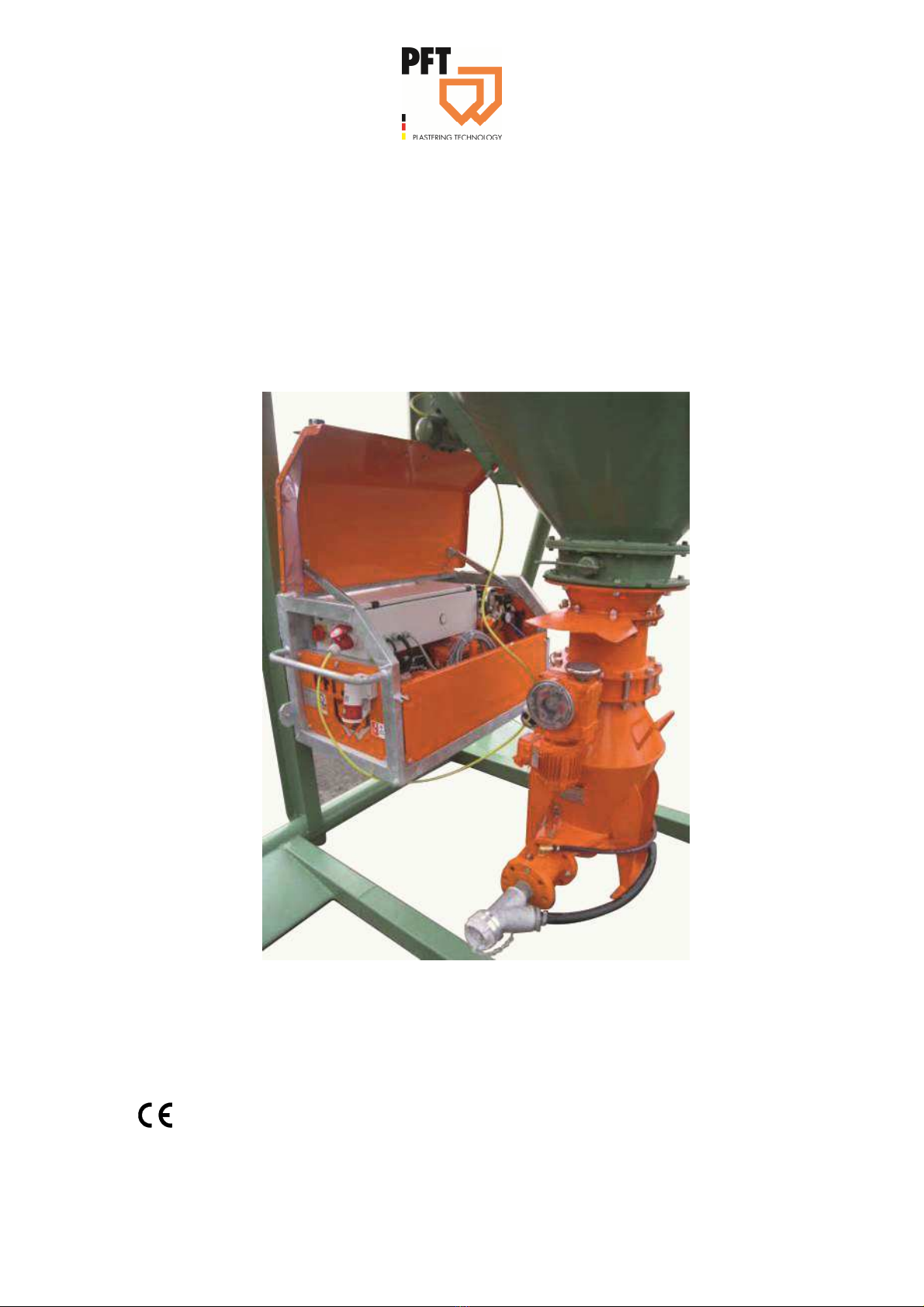
Assembly SILOJET III XXL ............... 11
7.1 Overview of the assembly units ............. 11
7.2 Frame with built-in parts ........................ 12
7. SILOJET III XXL pressure control.......... 1
7.4 Control cabinet and connections ........... 14
7.5 SILOJET III XXL carrier ......................... 15
8 Brief description ............................... 15
8.1 Conveying programme / work flow after
restart ................................................. 16
8.2 Conveying programme / work flow when
system is on standby ......................... 16
8. Intended purpose ................................... 17
9 Transport, packing and storage ...... 1
9.1 Safety instructions for transport ............. 17
9.2 Transport ................................................ 18
9. Transport inspection .............................. 18
9.4 Packaging .............................................. 19
9.5 Safety ..................................................... 19
10 SILOJET preparations .................... 20
10.1 Connecting the power supply .............. 21
10.2 Connect the carrier to the silo .............. 21
10. Connect conveying hoses .................... 21
11 Laying conveyor lines .................... 22
12 Connections .................................... 23
13 Opening the silo discharge flap
valve ............................................... 23
14 Hazardous dusts ............................. 24
15 Switching on and putting into
operation ........................................ 24
16 Switching off ................................... 25
1 Stopping in case of emergency ..... 26
18 Faults ............................................... 26
18.1 Safety ................................................... 27
19 Fault display .................................... 29
19.1 The following installation indicates
faults: ................................................. 29
19.2 Table of faults ...................................... 29
20 Work on troubleshooting ............... 31
20.1 Removal of clogging in hoses .............. 1
20.2 Opening the shut-off flap valve ............ 1
20. Relieving the pressure ......................... 2
20.4 Check the motor protection switch ....... 2
20.5 Restart the system after a blockage .... 2
21 Action in case of power cut ........... 32
21.1 Establishing a de-energised state ........
22 End of work ..................................... 33
22.1 End of work or interruption of work ......
23 Remove the carrier ......................... 34
2 .1 Empty the carrier .................................. 4
24 Cleaning ........................................... 34
24.1 Cleaning the conveying system ........... 4
25 Maintenance .................................... 35
25.1 Safety ................................................... 5

PFT SILOJET III XXL T 120, 7.8 kW, 60 Hz Part 2 Overview – Operation - Spare parts lists
EC Declaration of Conformity
Page 4 11.11.2016Page 4 of 80
26 Maintenance .................................... 3
26.1 Maintenance plan ................................. 7
26.2 Maintenance work ................................ 7
2 Clean the filter ................................. 38
27.1 Remove the filter cover ........................ 8
27.2 Check the slider width .......................... 9
27. Actions after completed maintenance .. 41
28 Disassembly .................................... 41
28.1 Safety ................................................... 41
28.2 Disassembly ......................................... 42
28. Disposal ............................................... 42
29 Spare parts drawing, spare parts
list ................................................... 44
29.1 SILOJET III T carrier ............................ 44
29.2 SILOJET III T carrier ............................ 46
29. SILOJET III XXL frame ......................... 48
29.4 Rotary compressor KDT .120 T 7.8
KW article number 00 21 20 08 ......... 50
29.5 Pressure control SILOJET T120 60 Hz
DFQ complete .................................... 54
29.6 Compressed air reservoir SILOJET
T120 60 Hz......................................... 56
29.7 Air compressor K 1 ............................... 58
29.8 Pressure switch-off for compressor K 160
29.9 SILOJET III XXL 60 Hz control cabinet 62
30 Annexe ............................................. 66
0.1 Checklist for expert assessment .......... 66
31 Circuit diagrams .............................. 6
32 Index ................................................. 6
-+

PFT SILOJET III XXL T 120, 7.8 kW, 60 Hz Part 2 Overview – Operation - Spare parts lists
EC Declaration of Conformity
11.11.2016
Page 5
11.11.2016
1 EC Declaration of Conformity
Company: Knauf PFT GmbH & Co. KG
Einersheimer Straße 5
97 46 Iphofen
Germany
declares under our sole responsibility that the product:
Type of machine: SILOJET
Type of equipment: Pneumatic conveying system
Serial number:
Guaranteed sound power level: 101 dB
is in conformity with the following CE directives:
• Outdoor directive (2000/14/EC),
• Machine directive (2006/42/EC),
• Electromagnetic Compatibility Directive (2014/30/EG).
Operative Conformity Assessment according to Outdoor Directive 2000/14/EC:
Internal production control as per article 14 paragraph 2 in connection with annex V.
This declaration only refers to the machine in the state in which it has been placed on the market. Parts
subsequently added by the user and/or subsequent interventions are not covered. This declaration ceases to
be valid if the product is converted or changed without consent.
Person authorised to compile the relevant technical documentation:
Dipl.-Wirtsch.-Ing. (FH) Michael Duelli, Einersheimer Straße 5 , 97 46 Iphofen.
The technical documentation is available from:
Knauf PFT GmbH & Co.KG, Technical Department, Einersheimer Straße 5 , 97 46 Iphofen.
Iphofen,
Dr. York Falkenberg
Managing Director
Place, Date of issue
Name and signature
Details about the signatory

PFT SILOJET III XXL T 120, 7.8 kW, 60 Hz Part 2 Overview – Operation - Spare parts lists
Examination
Page 6 11.11.2016Page 6 of 80
2 Examination
2.1 Examination by machine operator
Prior to each shift, the machine operator has to
examine the effectiveness of the control and safety
devices as well as the proper fitting of the protection
devices.
The safe working condition of construction machinery
has to be checked by the machine operator during
operation.
If the safety devices show any defects or if any other
defects are detected that compromise a safe operation,
the supervisor has to be informed immediately.
In case of defects that cause harm to persons, the
operation of the construction machine has to be
stopped to eliminate the defects.
2.2 Periodic inspection
Construction machinery has to be inspected for their
safe working condition in accordance with the operating
conditions and the operational requirements as needed,
however at least once a year by an expert.
Pressure vessels have to undergo the prescribed expert
inspections.
The inspection results have to be documented and kept
at least until the next inspection.

PFT SILOJET III XXL T 120, 7.8 kW, 60 Hz Part 2 Overview – Operation - Spare parts lists
General information
11.11.2016
Page 7
11.11.2016
3 General information
3.1 Information regarding the operating manual
This operating manual gives important information on
handling the device. A prerequisite for safe working is
the observance of all stated safety guidelines and
instructions.
Furthermore, the local accident prevention guidelines
and general safety instructions for the application area
of the device are to be adhered to.
Read the operating manual thoroughly before starting
any work! It is a part of the product and has to be kept
near the tool and easily accessible to the staff at all
times.
If the tool is given to third parties, also include the
operating manual.
The figures in this manual are for presentation purposes
of facts not necessarily to scale and may slightly differ
from the actual model of the device.
4 Division
The operating manual is divided into 2 books:
Part 1 Safety (article number of the operating manual
001 2670)
Part 2 Overview, operation, service and spare parts
lists. (This book)
For safe operation of the device, both the parts have to
be observed. Together they form one operating manual.
4.1 Keep a copy of the manual
The operating manual has to be available during the
whole service life of the product.
4.2 Accessories
For other accessories, please visit www.pft.de or consult your PFT construction machine dealer.

PFT SILOJET III XXL T 120, 7.8 kW, 60 Hz Part 2 Overview – Operation - Spare parts lists
Technical data
Page 8 11.11.2016Page 8 of 80
5 Technical data
5.1 General information
SILOJET XXL III T RAL2004
00 44 96 0
5.2 Power connection
Electrical
Particular Value
Unit
Voltage Ph./ 50 Hz 400
V
Power consumption approximately
21
A
Power input 9.
kW
CEE connection, 5-pin 2
A
Fuse protection, at least 2A typ C
Motor protection switch
Fig. 1 motor protection switch
Power Setting
value
Designation
Compressor I 7.8kW 18A Q
Compressor II 0.5 kW 1.2 A Q2
Actuator 0.18kW 0.65 A Q4
Vibrating unit 0.5 kW 1.2 A Q5
Particular Value
Unit
Weight 66
kg
Length 1280
mm
Width 719 / 625
mm
Height 6 0
mm
Carrier 106
kg
Compressor KDT .120 T 1 0
kg
Complete frame 78.5
kg
Control cabinet 2 .5
kg

PFT SILOJET III XXL T 120, 7.8 kW, 60 Hz Part 2 Overview – Operation - Spare parts lists
Technical data
11.11.2016
Page 9
11.11.2016
5.3 Operating conditions
Environment
Particular Value
Unit
Temperature range 2-45
°C
Relative humidity, max. 80
%
Duration
Particular Value
Unit
Max. operating time at a stretch 8
hours
5.4 Power values
Particular Value
Unit
Feed range in m* up to 200
Metre
Feed rate up to 44
kg/min
Operating pressure, max. 2.5
bar
Compressor intake volume 118
Nm³/h
* Reference value depending on the material quality, material weight and
conveying height
5.5 Sound power level
Sound power level L
WA
101 dB (A)
5.6 Vibrations
Weighted effective value of acceleration to which the upper body parts are exposed <2.5 m/s²

PFT SILOJET III XXL T 120, 7.8 kW, 60 Hz Part 2 Overview – Operation - Spare parts lists
Indicator light, time and setting data
Page 10 11.11.2016Page 10 of 80
6 Indicator light, time and setting data
Red indicator light Motor failure, smaller or bigger compressor
Red flashing indicator light Control air pressure is too low, system switches off
Yellow indicator light Change direction of rotation
Green indicator light System ready for operation
Green flashing indicator light Material requirement
Push button for control voltage “ON”, white Ready for operation, no fault
Push button for control voltage flashing, white Acknowledge fault with “ON” / “OFF”
T 1 = 10 seconds Initial start, check whether the conveying hoses are
empty
T 2 = 10 seconds Fill time for carrier, flap valve OPEN/ CLOSE
T = 45 seconds Carrier empty, refill
T 4 = 10 seconds Open flap valve, fill time for carrier
T 5 = 15 minutes System stops, blow the conveying hoses until they are
empty
T 6 = seconds Delay in opening the flap valve
T 7 = / (20) seconds Vibrating unit – interval while filling the tank
T 16 = seconds Flap valve opens with a delay
Time relay – requirement = seconds Requirement must be pending for seconds continuously
Pressure switch S4, systems - overload
switching
Switches to bypass air at 1.9 bar
Pressure switch S5, conveying hose empty System is switched off at 0.5 bar empty blowing pressure
Pressure switch S6, control air – monitoring If the control pressure falls below 2. bar, it is notified as
a fault; the system switches off after the carrier is emptied
Pressure switch-off, control air compressor bar ON / 4 bar OFF
Motor protection switch, conveying compressor 18 ampere setting
Bypass valve Y1 is on Y2 while switching over Open for one second longer (open in parallel for one
second)

PFT SILOJET III XXL T 120, 7.8 kW, 60 Hz Part 2 Overview – Operation - Spare parts lists
Assembly SILOJET III XXL
11.11.2016
Page 11
11.11.2016
Assembly SILOJET III XXL
.1 Overview of the assembly units
1 2
10
9
Fig. 2: Table of the assembly groups
1. Complete frame, SILOJET III XXL
2. Rotary compressor KDT .120 in the frame
. Silo shut-off flap valve
4. Connecting piece
5. Shut-off unit
6. Actuator type 6
7. Carrier
8. Squeeze valve
9. Bypass
10. Material hose connection to the cleaning machine
11. Main terminal 2A
12. Control cabinet in the frame
4
5
6
7
8
12
11

PFT SILOJET III XXL T 120, 7.8 kW, 60 Hz Part 2 Overview – Operation - Spare parts lists
Assembly SILOJET III XXL
Page 12 11.11.2016Page 12 of 80
.2 Frame with built-in parts
1 2
9 8 7 6 5 4
Fig. 3: Overview of the rotary compressor
1. SILOJET III XXL control cabinet
2. SILOJET III XXL cover hood
. SILOJET III XXL pressure control
4. Rotary compressor with KDT .120 filter
5. Filter for rotary compressor
6. Pressure control for compressor K1
7. Compressor K1
8. Control cable for actuator
9. SILOJET III XXL frame galvanised

PFT SILOJET III XXL T 120, 7.8 kW, 60 Hz Part 2 Overview – Operation - Spare parts lists
Assembly SILOJET III XXL
11.11.2016
Page 1
11.11.2016
.3 SILOJET III XXL pressure control
1 2 4
14
1
12
11
10
Fig. 4: Overview of the pressure control
1. Pressure switch for follow-up time / conveying hose
is empty
2. Solenoid valve for conveying air
. Solenoid valve for bypass air
4. Non-return valve
5. Pressure gauge 0-4 bar, pressure for conveying air
6. Connection for conveying air
7. Pressure gauge 0-4 bar, pressure for bypass air
8. Connection for bypass air
9. Control air squeeze valve
10. Solenoid valve, squeeze valve
11. Pressure gauge 0-4 bar, pressure in the silo
12. Pressure switch for monitoring, control air
1 . Safety valve 2.8 bar
14. Pressure switch for conveying air, anti-blockage
control
5
6
7
8
9

PFT SILOJET III XXL T 120, 7.8 kW, 60 Hz Part 2 Overview – Operation - Spare parts lists
Assembly SILOJET III XXL
Page 14 11.11.2016Page 14 of 80
.4 Control cabinet and connections
1
2 4 5
7 6
Fig. 5: Overview of the control cabinet an connections
1. Master switch is also emergency-stop switch
2. Push button for control voltage “ON/ OFF”
.
***
Pilot lamp
4. Power socket for requirement/level sensor
5. Power socket for vibrating unit connection
6. Main terminal 2A
7. Control cable for actuator
ORANGE, change direction of rotation
RED, motor protection switch fault
RED – flashing, very low control air pressure
GREEN, system ready for operation
GREEN – flashing, system requires material
*** For
functions of
the pilot
lamp, see
below

PFT SILOJET III XXL T 120, 7.8 kW, 60 Hz Part 2 Overview – Operation - Spare parts lists
Brief description
11.11.2016
Page 15
11.11.2016
.5 SILOJET III XXL carrier
1 2 4 5
9 8 7 6
Fig. 6: Overview of the SILOJET III XXL carrier
1. Actuator type 6
2. Hand-wheel, shut-off flap valve open/
CLOSE
. Connecting piece for SILOJET carrier
4. Shut-off unit
5. Ball valve for manual bypass system
6. Conveying air from the compressor
7. Ball valve for manual bypass system
8. Emulsifier - cleaning cover
9. Bypass air from the rotary compressor
10. Conveying hose connection
11. Squeeze valve
12. Control air for squeeze valve
8 Brief description
The PFT SILOJET III XXL is a fully-automatic, pneumatic conveying system.
It takes over the material transport of premixed dry mortar from the silo / container to the
cleaning machine.
12
11
10

PFT SILOJET III XXL T 120, 7.8 kW, 60 Hz Part 2 Overview – Operation - Spare parts lists
Brief description
Page 16 11.11.2016Page 16 of 80
8.1 Conveying programme / work flow after restart
Step 1: connect the electric current, conveying hoses and level control. Open silo discharge flap
valve on the silo / container.
Step 2: switch on the main switch.
Step 3: press the green push button for control voltage “ON/ OFF”.
Step 4: the system starts and checks whether the conveying hoses are empty. The flap valve,
squeeze valve and conveying air solenoid valve are closed in this case. The conveying air is
directed to the conveying hose via the bypass; it can thus be checked whether the hoses are free
without using an additional manual function after a blockage and the cleaning of the conveying
hose.
Step 5: If there is no material requirement (green pilot lamp lights up) after checking the hoses, the
system switches to standby.
Step 6: If there is a material requirement (green pilot lamp flashes) after checking the hoses, the
squeeze valve is opened and the conveying process starts.
8.2 Conveying programme / work flow when system is on standby
Step 1: Cleaning machine requires material.
Step 2: After a three-second long level sensor requirement, the green lamp switches to flashing
green.
Step 3: The squeeze and solenoid valves for conveying air open and the compressor starts. The
process of conveying the material starts.
Step 4: If the supply pressure in the conveyor line is too high, the system switches over from
conveying air to bypass air; the compressor is thus not overloaded. The squeeze valve is also
closed during this switching process; the pressure in the hose reduces and the material supply is
interrupted at the same time.
Step 5: If the pressure falls to 1.6, the system restarts with the conveying programme.
Step 6: The carrier is refilled every 45 seconds during the conveying process; the system switches
from conveying to bypass air in the process. The squeeze valve closes and the shut-off flap valve
opens; the vibrating unit thereby supports the material flow from the silo into the carrier.
Step : The shut-off flap valve closes and the squeeze valve opens.
Step 9: The solenoid valve for conveying air opens and the solenoid valve for bypass air closes.
Step 10: If the cleaning machine is full, the conveying air switches over to bypass air. The squeeze
valve closes and the conveying hose is blown until it is empty. The system goes into the standby
position.
A requirement can again be received in between due to the large conveying range, although the
conveying hoses have still not been blown until they are empty. In this case, the system
immediately switches over to the conveying mode.

PFT SILOJET III XXL T 120, 7.8 kW, 60 Hz Part 2 Overview – Operation - Spare parts lists
Transport, packing and storage
11.11.2016
Page 17
11.11.2016
8.3 Intended purpose
The rotary compressor can be used for generating overpressure.
The operation is intended only for normal atmospheric air. Not for conveying toxic or combustible
mediums. The compressor works without oil. Avoid oil mist from getting sucked in. The
specifications are applicable up to a height of 800 m above sea level.
9 Transport, packing and storage
9.1 Safety instructions for transport
WARNING!
Occupational safety!
During transport, assembling and dismantling of
the system, operation, maintenance and cleaning,
the national and international regulations
applicable in each case must be adhered to, even
if they have not been explicitly mentioned in this
manual.
Improper
transport
ATTENTION!
Damage from improper transport!
Improper transport may cause substantial property
damage.
Therefore:
– When unloading the packages on delivery as
well as transport within the company pay
attention and observe the symbols and
instruction on the package.
– Use only the specified anchorage points.
– Remove packaging only shortly before the
assembly.

PFT SILOJET III XXL T 120, 7.8 kW, 60 Hz Part 2 Overview – Operation - Spare parts lists
Transport, packing and storage
Page 18 11.11.2016Page 18 of 80
Suspended loads
WARNING!
Danger to life from suspended loads!
When lifting heavy loads there is danger to life from
falling parts or uncontrolled swinging parts.
Therefore:
– Never step under suspended loads.
– Observe the instructions regarding the provided
anchorage points.
– Do not fix at projecting machine parts or eyelets
of attached components and ensure safe fit of
the sling gear.
– Use only approved lifting gear and sling gear
with sufficient lifting capacity.
9.2 Transport
Transport of already running
machine
DANGER!
Risk of injury due to discharged dry material!
Injuries to face and eyes can occur.
Therefore:
– Before opening the hose couplings, ensure that
the hoses are depressurised.
Carry out the following steps before beginning the transport:
1. Unplug the mains cable.
2. Remove the conveying hoses.
9.3 Transport inspection
On receipt check the delivery immediately for
completeness and transport damage.
In case of externally visible transport damage, proceed
as follows:
Do not accept the delivery or under reserve only.
Note the extent of damage on the transport
documentation or on the delivery note of the carrier.
Initiate complaint process.
NOTE!
Report any efect as soon as it is etecte . Claims
for amages can be asserte only within the vali
warranty perio .

PFT SILOJET III XXL T 120, 7.8 kW, 60 Hz Part 2 Overview – Operation - Spare parts lists
Transport, packing and storage
11.11.2016
Page 19
11.11.2016
9.4 Packaging
For packaging The individual packages have to be packed in accordance with the
transport conditions to be expected. Only environmentally-friendly
materials were used for the packaging.
The packaging should protect the individual components until the
assembly from transport damage, corrosion and other damage.
Therefore do not destroy the packaging and remove only shortly
before the assembly.
Handling packaging
materials
If no agreement for the recovery of the packaging has been made, separate
materials according to type and size and reuse or recycle.
ATTENTION!
Environmental damage due to wrong disposal!
Packaging materials are valuable raw materials and in many
cases they can be reused or reconditioned and recycled.
Therefore:
– Dispose of packaging materials in an environmentally-
friendly way.
– Observe the applicable local disposal regulations. If required
hand over the disposal to a specialist.
9.5 Safety
Personal protective
equipment
The following protective equipment has to be worn for all operative work:
Protective clothing
Protective goggles
Protective gloves
Safety shoes
NOTE!
Further protective equipment that is to be worn
when effective particular jobs will be pointe out
separately in the warning instructions of this
chapter.

PFT SILOJET III XXL T 120, 7.8 kW, 60 Hz Part 2 Overview – Operation - Spare parts lists
SILOJET preparations
Page 20 11.11.2016Page 20 of 80
Basic information
WARNING!
Danger of injury due to incorrect operation!
Improper operation may lead to serious damage to persons or
property.
Therefore:
– Carry out all the operating steps according to the instructions
in this user manual.
– Prior to starting your work, ensure that all the covers and
protection devices are installed and work as intended.
– Never deactivate the protection devices during operation.
– Ensure order and cleanliness in the work area! Loose
components and tools on top of another or lying about pose
potential accident risks.
10 SILOJET preparations
Prior to operating the machine carry out the following steps for preparing the
machine:
Warning!
SILOJET systems for free-fall silos may be connected only to
depressurised silos / containers. The dedusting lines of the
silo / container must be open and free from blockages.
NOTE!
In order to avoid condensate from entering the system, do the following before starting work:
Decouple the air hose, which is coming from the compressor, from the carrier.
Switch on the compressor while adhering to the direction of rotation.
Air must be discharged from the coupling (remove the air hose). In case of an incorrect
direction of rotation, bring the main switch to the zero position.
Push the selector membrane to the opposite side and switch on the main switch for the
other direction; the direction of rotation is changed.
Let the compressor run for approximately 2– minutes.
Kink the hose end several times in the process and re-release it after a brief pressure build-
up.
Repeat the process until water mist is no longer discharged from the air hose.
Switch the system off by pressing the red push button, operation “OFF”.
1. Install the system on a stable and level surface.
Install the system such that it cannot be affected by objects that are falling down.
The operating elements have to be freely accessible.
This manual suits for next models
1
Table of contents
Other Knauf PFT Construction Equipment manuals