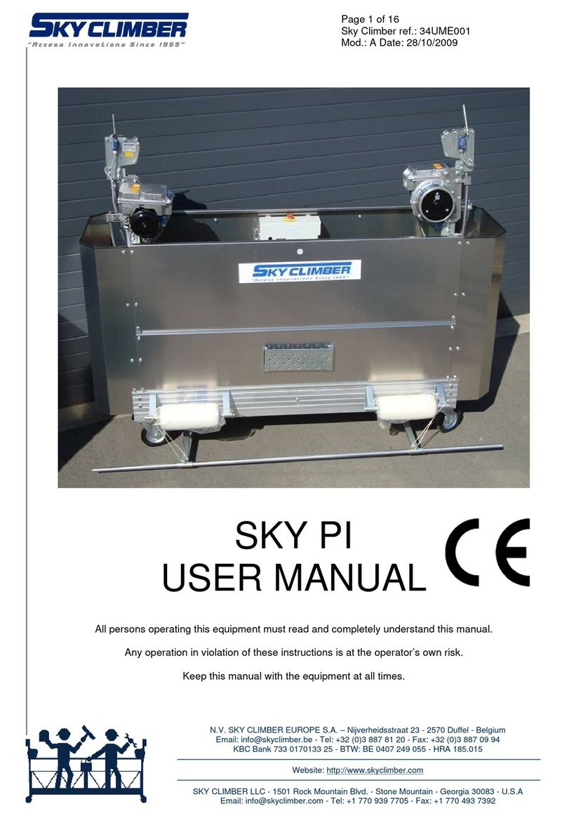
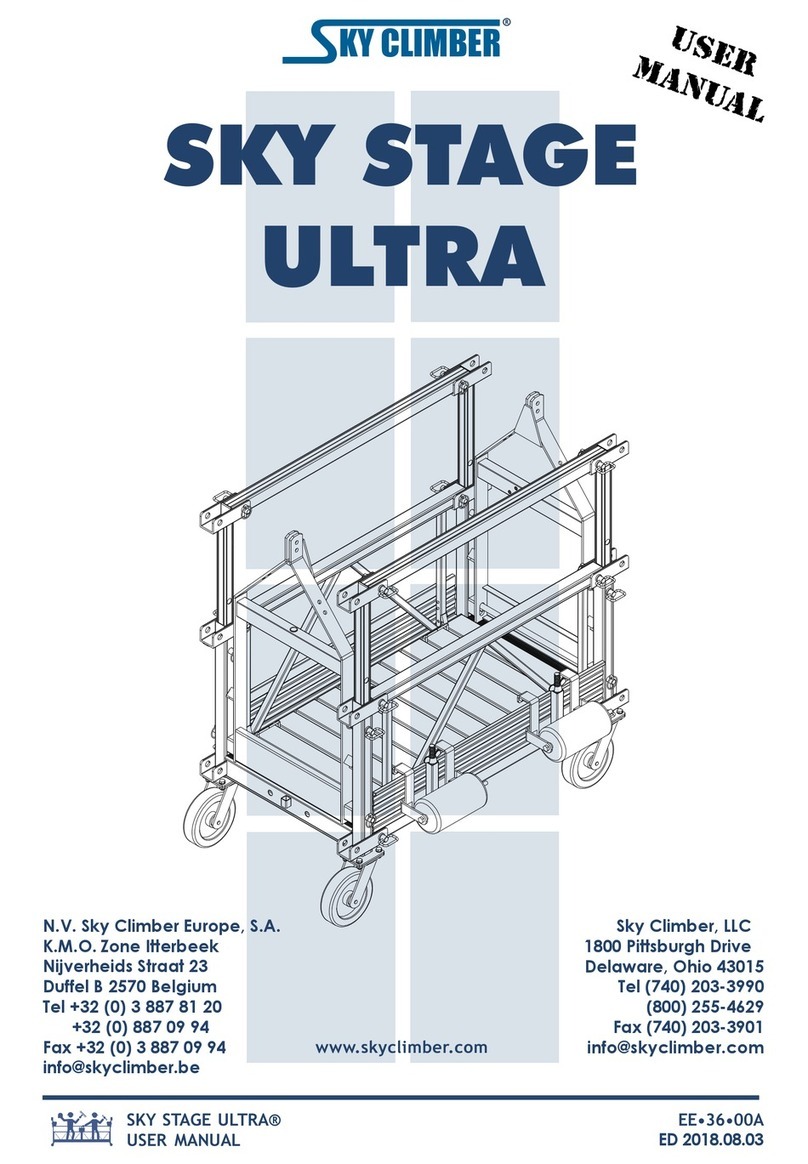
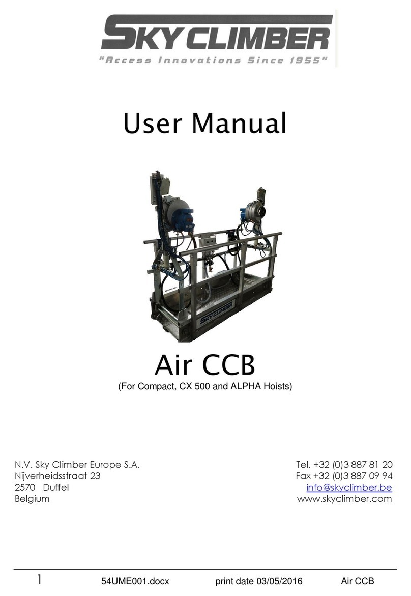
Sky Climber IC1000 User manual

1 IC-1000 Operators Manual Revision: 2
4/23/2018
IC1000
OPERATOR’S MANUAL

2 IC-1000 Operators Manual Revision: 2
4/23/2018
Contents
1.0 SAFETY GUIDELINES .......................................................................................................................... 4
1.1 INTRODUCTION............................................................................................................................. 4
1.2 OPERATOR..................................................................................................................................... 4
1.3 SAFETY EQUIPMENT...................................................................................................................... 4
1.4 GENERAL ....................................................................................................................................... 4
1.5 SYSTEM SUPPORT ......................................................................................................................... 5
1.6 STEEL WIRE ROPE.......................................................................................................................... 5
1.7 POWER SUPPLY GUIDELINES......................................................................................................... 6
1.8 CONTROLS..................................................................................................................................... 6
1.9 OPERATOR’S SUPPORT/WORK PLATFORM................................................................................... 6
1.10 ENVIRONMENTAL HAZARDS ..................................................................................................... 7
1.11 HAZARDOUS ACTIVITIES: WELDING.............................................................................................. 7
1.12 CORROSIVE ATMOSPHERE ............................................................................................................ 7
1.13 SAFETY LABELS / INSTRUCTIONS................................................................................................... 8
2.0 GENERAL OPERATION GUIDELINES................................................................................................... 9
3.0 WIRE ROPE INSPECTION AND SERVICE ...........................................................................................10
3.2 REMOVING AN OLD WIRE ROPE .................................................................................................10
3.3 INSTALLING NEW WIRE ROPE .....................................................................................................11
3.4 WIRE ROPE GUIDE ASSEMBLY.....................................................................................................11
3.5 TRANSFER CHAIN ASSEMBLY ......................................................................................................11
4.0 TENSION HOLDER ASSEMBLY..........................................................................................................12
4.1 INSPECTION.................................................................................................................................12
4.2 SERVICE .......................................................................................................................................12
5.0 WIRE ROPE DRUM AND AUTOMATIC EMERGENCY BRAKE ............................................................12
5.2 INSPECTION.................................................................................................................................13
5.3 SERVICE .......................................................................................................................................13
6.0 WIRE ROPE LEVEL WINDING SYSTEM .............................................................................................13
6.2 INSPECTION.................................................................................................................................13
6.3 SERVICE .......................................................................................................................................14
7.0 TRANSMISSION ..............................................................................................................................14
7.1 INSPECTION.................................................................................................................................14

3 IC-1000 Operators Manual Revision: 2
4/23/2018
7.2 SERVICE .......................................................................................................................................14
8.0 OVERLOAD SWITCH.........................................................................................................................14
8.2 INSPECTION.................................................................................................................................14
8.3 SERVICE .......................................................................................................................................15
9.0 AIR HOIST MOTOR...........................................................................................................................15
9.2 INSPECTION.................................................................................................................................15
9.3 SERVICE .......................................................................................................................................15
9.4 TROUBLESHOOTING AIR MOTOR................................................................................................ 15
10.0 OILER AND FILTER ........................................................................................................................... 16
10.2 INSPECTION AND SERVICE .......................................................................................................... 16
11.0 FRAME............................................................................................................................................. 16
11.2 INSPECTION AND SERVICE .......................................................................................................... 16
12.0 STORING AND TRANSPORTING....................................................................................................... 16

4 IC-1000 Operators Manual Revision: 2
4/23/2018
1.0 SAFETY GUIDELINES
Read and follow this safety check list. It includes all safety requirements of State and National
codes as well as the recommendations of Sky Climber Europe. Follow all applicable Federal,
State and Local codes and regulations pertaining to safety; they are minimum standards for the
safe operation of SkyClimber equipment.
1.1 INTRODUCTION
Sky Climber Hoists and accessories are designed and manufactured to the highest standards in
the industry for your safety. CAREFULLY FOLLOWING THE INSTRUCTIONS IN THIS MANUAL
WILL REDUCE THE RISK OF ACCIDENTS WHILE USING THIS PRODUCT. It is the operator’s
responsibility to be sure that anyone using this equipment is fully familiar with this Manual before
using the Sky Climber hoist and related equipment. Once the equipment leaves Sky Climber’s
control, the operator is responsible for its safe use, operation, and maintenance.
1.2 OPERATOR
1.2.1 Operators who operate suspended equipment must be:
•Mentally and physically able to withstand the stress of working at elevations.
•Able to read and understand this manual and follow its instructions.
1.2.2 If an operator is subject to seizures or loss of physical control, he shall not work at elevations
1.2.3 Operators must be safety conscious, responsible, and not under the influence of alcohol, drugs
or other substances.
1.3 SAFETY EQUIPMENT
1.3.1 All persons using suspended access equipment must at all times wear safety harnesses
attached by lanyards and rope grabs to independently hung lifelines. Do not disconnect/remove
safety belts, harnesses or lanyards until you are safely on the ground or until completely
disembarked from suspended devices to a safe location.
1.3.2 Use a short lanyard, and maintain the rope grabs high on the lifeline as practical.
1.4 GENERAL
1.4.1 Know and understand the operation of this equipment. Be sure that all persons who service,
erect, dismantle or use this equipment are thoroughly familiar with, and follow all the safety
rules in this Manual. Make certain that they also comply with all Federal, State and Local codes
and regulations that apply to this equipment and its safe use.
1.4.2 Training in the use of Sky Climber equipment is available. Contact Sky Climber for details.
1.4.3 Safety Helmets shall be worn at all times that an overhead hazard exists when servicing,
erecting, disassembling, or using this equipment.
1.4.4 Provide protection for operators from collision with overhead obstacles and falling objects.
1.4.5 Provide protection below the suspended equipment to prevent injury to personnel from falling
objects.
1.4.6 Keep all persons from beneath suspended equipment.
1.4.7 Never work alone on a suspended platform or where aid is not immediately available in case of
an emergency. Maintain contact with your supervisor at all times.
1.4.8 Do not exceed the rated capacity of the platform.
1.4.9 Before and after using, check all parts for proper function and damage to component parts. Do
not use a damaged or improperly functioning work cage. The supervisor should assign a
competent person to conduct the inspections.
1.4.10 In the case of apparent difficulty in the machine, steel wire rope, platform etc., notify your
nearest authorized Sky Climber representative, and do not use the equipment until it is
repaired or replaced.

5 IC-1000 Operators Manual Revision: 2
4/23/2018
1.4.11 All suspended access equipment must be handled with care. Impose loads on the platform
gently.
1.4.12 Use only Sky Climber genuine spare parts for your Sky Climber equipment. Do not alter any
SkyClimber baskets or accessories.
1.4.13 When at work station or when getting on or off a suspended working platform, prevent the
platform from moving away from the building or structure by securing the suspended platform
to the building face or structure. Before moving the platform always disconnect it from the
building face. Hardware may be damaged and personal injury may result if platform is not
disconnected from the building before it is raised or lowered.
1.5 SYSTEM SUPPORT
1.5.1 Make certain the roof, parapet or cornice will support the load imposed by the suspended
platform. Do not secure to a weak or questionable structure. When in doubt, consult a
professional engineer and/or the building owner’s qualified representative.
1.5.2 Make certain the supporting devices, such as: “A”-frame, parapet clamp, cornice hook or
roof beam will support the suspended platform load with a minimum of 4:1 safety factor. In
case of doubt, consult a professional rigger/engineer.
1.5.3 Tie-backs shall be used on all supporting devices. Tie-backs must be perpendicular to the
building facade, kept tight and attached to a structural member being capable of supporting the
entire suspended load as well as the support system. Note: Davits or other direct connections to
structure that are designed by a Professional Engineer may not require additional tiebacks.
1.5.4 Always use the correct type and size of wire rope clamps. Steel wire rope will slip through
oversize clamps. Undersize clamps will damage the steel wire rope.
1.5.5 Never use a fluid of free-flowing material in a container as counterweight. Always use a solid
material (with weight marking), that can be properly secured to the outrigger. Sandbags or
liquid-filled containers shall never be used as counterweight.
1.5.6 The nut-type used for assembling suspension systems shall be of the self-locking type.
1.5.7 Never move a suspension support or roof beam with the platform being suspended. The
platform shall be lowered onto a solid surface and the suspension wires shall be slack before
the suspension supports are to be moved.
1.6 STEEL WIRE ROPE
1.6.1 Comply with codes, regulations and industrial standards which forbid or warn against the use
of kinked, bird-caged or damaged steel wire rope. Inspect the steel wire rope for wear and
damage prior to use and during operation. Steel wire rope is susceptible to serious damage if
not handled in accordance with these and other instructions in this Manual. Exposure to
concentrated acids, caustic material, corrosion, fire, electricity, undue heat or abuse damages
the steel wire rope. When such an exposure has occurred, replace the steel wire rope
immediately.
WARNING: The use of kinked, birdcaged or excessively worn or damaged steel wire rope
is unlawful. Such use may result in injury or death to yourself or others.
1.6.2 Use Sky Climber specified steel wire rope, clamps, thimbles and other work associated
components.
1.6.3 Ensure the wire rope is long enough to reach the lowest possible landing.
1.6.4 Steel wire rope must be rigged to remain vertical, with suspension points directly above the
hoist entry guide or lead-in device at all times.
1.6.5 Tighten wire rope clamps in accordance with the clamp manufactures guidelines.
1.6.6 Special precautions must be taken to protect the steel wire rope when welding. See section
1.11 for list of precautions.

6 IC-1000 Operators Manual Revision: 2
4/23/2018
1.6.7 Wire rope fittings such as terminators, fist grips (aka: ‘j-clips or double-saddle clips’), shackles,
other connectors, and swage fittings all must be checked for proper torque/tightness at initial
loading, and at the beginning of each work shift.
1.6.8 Examine wire rope for damage when operating the hoist on each ascent and descent.
1.7 POWER SUPPLY GUIDELINES
1.7.1 Be sure your power supply conforms to hoist manufacturer’s recommendations.
1.7.2 Do not allow the electrical power supply cable / air hose to become tangled with any
obstruction or the suspension ropes when raising or lowering the suspended equipment.
Make certain the electrical cord/air hose is of sufficient length to allow full travel of the suspended
equipment.
1.7.3 Make sure that the electrical power source is grounded to a point of sufficient low resistance.
1.7.4 Use only approved connector plugs and power supply cords with strain relief, correctly
assembled from hoist to power supply. Verify ground continuity, and use a ground fault
interrupter (as required by code in your location). Consult local safety authorities for further
information.
1.7.5 Ensure that all metal parts, outlets, junction boxes and other components that might come in
contact with live conductors are properly grounded.
1.7.6 Always use a power cable cord with ground fault interrupter when using electrically driven hand
tools on a suspended platform. Verify that the hand tools are properly earthed.
1.7.7 Before using air powered hoists, check the air supply pressure setting of the pressure regulator.
The pressure setting should be equal to the working pressure indicated on the air motor decal.
1.7.8 Use only approved connector plugs and air hoses with strain relief, correctly assembled from
hoist to air distribution yoke.
1.7.9 Use an air hose of sufficient cross-section.
1.7.10 Use air hoses that are in good working condition.
1.7.11 In case the permissible noise level of 79dB is exceeded ear protection is necessary.
1.8 CONTROLS
1.8.1 Before switching on the main power: check all hoist controls and verify that they are in the
“neutral” or “off” position.
1.8.2 Before moving the platform, verify that all the persons on or close to the platform are
standing clear and are aware you are going to raise or lower the platform before moving.
1.8.3 Before raising or lowering the platform: check that the controls are operating as indicated on
the control panel. Activating the “UP” button / lever has to initiate the upward movement. If
this is not the case: call for a service mechanic.
WARNING: Always wait for the hoist to come to a complete stop before changing direction
of movement, otherwise this may result in loss of control.
1.9 OPERATOR’S SUPPORT/WORK PLATFORM
1.9.1 Check basket bolts daily and verify that the bolts are still in position and tightened firmly.
1.9.2 Never operate a suspended work-cage or platform without having the guard-rails, toe boards,
bumpers, lifelines, lanyards and safety harnesses in position.
1.9.3 When operating the platform keep it as level as possible. If necessary operate one hoist in
order to re-establish the level position.
1.9.4 When suspended do not climb or stand on guard-rails, toe boards, or platform supported
objects. Do not reach over the ends or sides of the platform. Do not use ladders or scaffolding
that are put on the platform deck for reaching out to higher levels.
1.9.5 Do not permit oil, grease, or slippery material to accumulate on climbing or gripping surfaces.
1.9.6 Do not attempt to bridge from one platform to another, nor to any other structure or other
equipment. Embarking/disembarking of the platform is only allowed at ground or roof level.

7 IC-1000 Operators Manual Revision: 2
4/23/2018
1.9.7 Do not attempt to transfer a work platform to another “drop” while suspended. Only transfer the
platform from one suspension location to another when it is lowered and standing on a level
and solid surface.
1.9.8 In order to prevent damage to the aluminum structure every contact with caustic materials,
acids fluids and fumes is strictly prohibited. Select wooden or fiberglass-made platforms for
working in a caustic environment.
1.10 ENVIRONMENTAL HAZARDS
WARNING: To avoid contact and shock hazard, scaffolds and tools should not be used in the
vicinity of energized power lines or electrical lines.
1.10.1 Refer to federal, state and local codes and regulations when working in the vicinity of electrical
overhead power lines. Consult the local power company for safe operating procedures before
rigging.
1.10.2 Do not use long-handled tools when working close to electric power lines.
1.10.3 Verify that there are no obstructions in the vertical travel zone of the platform. Always keep a
good look-out when raising or lowering the platform. If you run into an obstruction
immediately stop the platform and inspect the platform and obstruction for possible damage
and/or hang up. Proceed in a safe direction to clear the obstruction.
WARNING: Take care not to overload the system or get in a slack suspension wire situation
when running into an obstacle.
1.10.4 When using a hoist in or near a Marine (or corrosive/salty) environment, more frequent
inspections are required. In these applications a thorough 4-hours interval inspection of the
hoists, steel wire rope, fittings and equipment has to be executed. Make sure to replace all the
components that get degraded by corrosion or wear.
WARNING: Electric powered hoists are not rated for operating in an explosion
hazardous environment. Select an air powered hoist.
1.11 HAZARDOUS ACTIVITIES: WELDING
1.11.1 During welding, the electrocution hazard and the risk of the welding current passing through the
suspension steel wire ropes shall be eliminated by taking the following precautions:
1.11.1.1- Use an insulated thimble to attach each steel wire rope to its suspension point. Electrically
insulate the extra steel wire rope stored on the roof to prevent grounding, or terminate the
suspension rope at the insulated thimble.
1.11.1.2- Cover the steel wire rope with insulating material 4ft above and 4 ft below the wire rope guide.
1.11.1.3- Connect a ground conductor from the platform to the work piece. The size of this conductor
shall be equal to, or greater than the size of the stinger lead. NOTE: This must be a secondary
conductor and shall not be in series with the primary conductor between the welder and the work
piece.
1.12 CORROSIVE ATMOSPHERE
1.12.1 When Sky Climber hoists are being used in corrosive work-associated atmospheres such as acid
washing, the hoist and its supporting steel wire rope shall be protected from direct contact with
the corrosive solutions and agents. Each day, on the final descent, the steel wire rope shall be
washed with a neutralizing solution and re-lubricated. Stainless steel wire rope, which is far more
resistant to corrosion deterioration, can be obtained from Sky Climber.
1.12.2 Daily examination of the full supporting length of wire rope is mandatory.

8 IC-1000 Operators Manual Revision: 2
4/23/2018
1.13 SAFETY LABELS / INSTRUCTIONS
1.13.1 The Sky Climber equipment shall be labeled as follows:

9 IC-1000 Operators Manual Revision: 2
4/23/2018
2.0 GENERAL OPERATION GUIDELINES
2.1 Use the instructions in this manual and those provided with equipment to assemble the scaffold
and rigging equipment.
2.2 Every component of the rigging system must be able to support the load. All structural members
must be examined by an engineer or someone who is trained and capable of whether the
structure is capable of withstanding the loads applied. The structure must be able to support a
wire rope load of 4 times the maximum rated load capacity of the hoist. The gross load of
equipment, material, workers, and any other mass supported by each wire rope must not exceed
the rated capacity of hoist.
2.3 Clearly identify or remove obstructions in vertical path of travel. All power lines within 10ft of
suspended scaffold system should be de-energized and locked out. All equipment users need to
be aware of all cranes or other lifts on the structure/Jobsite. Identify any other hazards causing a
potential hazard.
2.4 Install rigging device to the structure so that the suspension line hangs plumb and passes straight
through the wire rope guide.
2.5 Independent safety lines, attached to anchorages separate from the suspension rope, should be
provided for each worker.
2.6 Connect to a power supply with fairlead side towards the face of the structure.
2.7 Release the tension holder and while pulling the wire rope operate the down switch until enough
wire rope is released to reach the rigging point. Maintain tension on the wire rope and tighten the
tension holder. Next operate basket in up position to apply tension to the wire rope. The wire
rope should be taunt before entering and exiting the stage.
2.8 When using a two point suspended scaffold, ensure the suspension points match up with the
basket hoists. Release the tension holder assembly when the basket is suspended and ensure
that the wire rope is winding correctly on the drum assembly.
2.9 All persons using the equipment should be trained in its use and know all local, state, and federal
regulations related to the use of suspended scaffolding, general safety and health precautions,
and personal protective and life saving equipment.
2.10 Any parts that have been exposed to excessive heat, as in the case of fire, should be immediately
removed from service and destroyed, due to loss of structural strength.
2.11 Do not use this product in cantilever applications.
2.12 Do not allow unstable objects or debris to accumulate on the work surfaces. Tools, materials,
and equipment should be secured and stored when not being used.
2.13 Never attempt to straighten a deformed/damaged part of work cage.

10 IC-1000 Operators Manual Revision: 2
4/23/2018
IC1000 BASKET
WARNING: Refer to the general operating instructions before using any equipment. Ensure that
all equipment has passed inspections and the gates are closed before operating basket.
3.0 WIRE ROPE INSPECTION AND SERVICE
3.1 Refer to OSHA 1926.1413 –Wire Rope Inspection.
3.2 REMOVING AN OLD WIRE ROPE
3.2.1 While the IC1000 basket is on the ground, run the versa valve in the down direction while pulling
the wire rope through the rope guide, until all of the wire rope is off the drum.
3.2.2 When the hook is free from the drum flange, rotate the drum into the 6 o’clock position, and then
disengage the hook through the hole in the drum flange.
3.2.3 Remove the tension holder handle and half of the tension holder assembly. Then, thread the
hook through the rope guide. Note: The rope guide assembly can remain in place during this
process.
WARNING: When the drum is moving, keep hands and all clothing free from drum.

11 IC-1000 Operators Manual Revision: 2
4/23/2018
3.3 INSTALLING NEW WIRE ROPE
Contact your Skyclimber dealer for information on swaging a new wire rope hook.
3.3.1 Use the reverse order for removing an old wire rope to install the new wire rope. Be sure when
the tension holder handle is reassembled, it is in the proper orientation so that when the handle is
in the down position it tightens the tension holder.
3.3.2 After the drum hook is properly installed, wind the wire rope on the drum using the UP direction of
the versa valve. Make sure the first wrap of the wire rope is tight against the drum flange and
every other wrap after is tight to the previous. It is important that the wire rope be wound tight
and evenly around the drum.
3.4 WIRE ROPE GUIDE ASSEMBLY
3.4.1 The wire rope guide is designed to help stabilize the unit during operation.
3.4.2 The guide rings have a hardened steel insert, which is designed to have minimal adverse effects
on wire rope.
3.4.3 The wire rope guide should be inspected before each use and if the guide rings are worn, they
should be replaced before use.
3.5 TRANSFER CHAIN ASSEMBLY
3.5.1 The forged transfer eye is used to suspend the weight of the basket and worker in order to
complete a mid-air transfer.

12 IC-1000 Operators Manual Revision: 2
4/23/2018
3.5.2 Run the transfer chain through the transfer eye. Secure the tail end of the chain back to itself
using two shackles on each side of the transfer eye.
3.5.3 Attach the sling hook and rigging hook to a structure that will support the total suspended weight.
3.5.4 Lower the basket until the load is transferred to the chain and there is sufficient slack in the
primary rope.
3.5.5 Move the wire rope to the new suspension point.
3.5.6 Raise the basket until there is tension on the wire rope and sufficient slack on the transfer chain.
3.5.7 Remove the transfer chain assembly.
4.0 TENSION HOLDER ASSEMBLY
4.1 INSPECTION
4.1.1 Without disassembling the tension holder, visually inspect the rubber rollers daily. (If definite
signs of wear are visible, then further examination is required.)
4.1.2 Every 30 days or at the first signs of wear, disassemble the tension holder and inspect the rollers
further for deep grooves or flat spots. Ensure all four rollers spin freely and the bearings are free
and lubricated.
4.1.3 If no further service is required, reassemble the rollers and tension holder so that the handle
tightens in the down position.
4.2 SERVICE
4.2.1 For bearing lubrication, remove the 4 bearing shields, located on each side of the roller
assemblies. Apply bearing grease to each bearing and then replace shields.
4.2.2 For bearing and roller replacement, contact your local Skyclimber dealer.
5.0 WIRE ROPE DRUM AND AUTOMATIC EMERGENCY BRAKE
5.1 The wire rope drum collects and releases wire rope during the Up and Down functions of the
basket. The automatic emergency brake is designed to stop the descent of the basket if the

13 IC-1000 Operators Manual Revision: 2
4/23/2018
transmission fails. NOTE: If an over speed condition occurs, the break can be reset by running
the basket in the UP direction. (Immediately following an emergency brake engagement, the
brake and transmission must be inspected by a qualified service technician before returning to
service.
WARNING: When at the bottom of a drop, maintain a minimum of 4 wire wraps around the drum.
5.2 INSPECTION
5.2.1 Every time a wire rope is replaced, inspect the drum for damage. Before the basket is sent to a
jobsite and every 30 days after, the automatic emergency brake should be inspected. NOTE: All
inspections should be performed by qualified personnel only.
5.2.2 Remove the inspection plate from drum flange, and ensure that the disc moves freely back and
forth. There should be a 1/16” gap between the disc and the drum flange and should also return
to original position when spun clockwise. The inspection plate should then be reinstalled if
everything is correct. Note: Inspection plate is sized for this application.
5.3 SERVICE
5.3.1 Contact your local Skyclimber representative, if the drum or automatic emergency brake require
attention.
6.0 WIRE ROPE LEVEL WINDING SYSTEM
6.1 When the basket is suspended, the level winding system ensures the wire rope spools evenly on
the drum. The spring allows the drum to tilt and ensure the wire rope stays perpendicular to the
drum during the winding process.
6.2 INSPECTION
6.2.1 Daily the operator should inspect the wire rope spooling on the drum to make sure it is stored
properly.
6.2.2 Every 30 days, inspect the drum base for damage. Check the tilt control assembly and pivot pins
for damage. Ensure the pivot pins are secured properly with snap rings. Check the tilt control
assembly to make sure it resists the tilt of the drum.

14 IC-1000 Operators Manual Revision: 2
4/23/2018
6.3 SERVICE
6.3.1 Contact your local Skyclimber representative, if the tilt control assembly or drum base requires
attention.
7.0 TRANSMISSION
7.1 INSPECTION
7.1.1 Every 30 days, (sooner if needed) check the oil level of both sections in the transmission through
the inspection holes. Use Mobile SHC 634 gear oil, (No substitutes), to fill both sections, when
the oil level is below the inspection holes. Using the same inspection holes check the bronze
gear for excessive wear. The bronze gear teeth have a width of 1/16” when brand new. If the
width of the teeth is decreasing and becoming sharp, it is time to replace the gear. Contact local
Skyclimber representative for replacing gear.
7.1.2 Every 12 months a complete oil change of both sections is required, (sooner if needed). Drain the
oil from both sections and replace with Mobile SHC 634 gear oil. Use one full quart to fill both
sections.
7.2 SERVICE
7.2.1 Contact your local Skyclimber representative, if the transmission requires attention.
8.0 OVERLOAD SWITCH
8.1 The overload switch prevents the wire rope, rigging, and hoist from becoming overloaded.
8.2 INSPECTION
8.2.1 Before installation on a new job, or every 30 days, the overload switch should be inspected for
proper use. Inspection should be conducted by trained personnel.
8.2.2 With the basket hanging from an adequate rigging beam, load the stage with the rated working
load as shown on the label. With the basket connected to proper air supply, the basket should lift

15 IC-1000 Operators Manual Revision: 2
4/23/2018
the load. Next add approximately 100 lbs, and now the overload switch should prevent travel in
the up direction.
8.3 SERVICE
8.3.1 If the overload switch is not properly set, adjust the bolt one turn at a time until the proper setting
is reached. Once the bolt is set at the appropriate height retightened the jam nut. If further
service is required contact your local Skyclimber representative.
9.0 AIR HOIST MOTOR
9.1 The air motor is a vane type motor rated at 1 hp, at 120 psi and 60 cfm air supply. The air supply
line needs to have at least a ¾” I.D. hose in order to achieve maximum horse power.
9.2 INSPECTION
9.2.1 At any point while air motor is running and the operator notices any unusual behavior, it should be
referred to a trained or knowledgeable person for further inspection. For unusual behavior,
reference trouble shooting air motor.
9.2.2 Before installation at a new jobsite or every 30 days, the air motor should be inspected by a
trained or knowledgeable person. Check the cover fasteners, make sure they are secure. Inspect
the housing for any signs of damage. Ensure all hoses are secure and not damaged.
9.3 SERVICE
9.3.1 Contact your local Skyclimber representative, if the air motor requires further attention.
9.4 TROUBLESHOOTING AIR MOTOR
Air motor is losing power and running slowly
Improper air supply
Ensure that air supply is at least 120 psi
and 60 cfm.
Too much or not enough air oil
Check the air lubricator oil level, make
sure it is clean, and properly adjusted. (4-6
drops/minute)
Plugged air filter
Clean air filter
Badly worn vanes or worn rotor bearing
Return for service.
Air motor running sluggish in down direction
Too much air oil
Adjust lubricator properly and run in down
direction to discharge excess oil.
Air motor will not move in either direction
Check for visible wear or scoring on parts
Return for service
Swollen vanes
Return for service

16 IC-1000 Operators Manual Revision: 2
4/23/2018
10.0 OILER AND FILTER
10.1 The filter helps remove moisture and dirt from air supply. The oiler lubricates the air for the motor.
WARNING: Oiler and filter are intended to be used with industrial compressed air systems. Do
not exceed rated temperature or pressure.
10.2 INSPECTION AND SERVICE
10.2.1 Disconnect air supply before proceeding. Daily, drain the filter by loosening drain screw on the
bottom of filter. After water has drained, reset the drain screw. Ensure oiler has sufficient oil and
the drip rate is set correctly.
10.2.2 Every 30 days, remove and clean the filter screen. (Sooner if needed because of extreme
conditions) Remove the filter bowl and empty. With the filter bowl off, remove the filter baffle
from bottom of filter and remove filter. Clean filter with thinner or solvent and then blow the filter
dry. Replace air filter and retightened baffle, DO NOT over tighten. Set oil drip rate to 4-6
drops/minute. Connect to air supply and run air motor full throttle in UP direction. While air motor
is running adjust the drip rate by loosening/ tightening on top of oiler. Loosening the screw
increases the drip rate an tightening the screw decreases the drip rate.
11.0 FRAME
11.1 The frame is constructed using high strength aluminum allows and welded using heliarc-welded
joints. Also, integrated into the frame design are wheels and a forged transfer eye.
WARNING: DO NOT use heat to clean debris from frame. If welds are cracked, frame is
damaged, or transfer eye is damaged contact your local Skyclimber representative.
11.2 INSPECTION AND SERVICE
11.2.1 The operator should inspect the frame and transfer eye daily for any damage. DO NOT use
basket if damage is noticed.
11.2.2 Before installing on a new jobsite or every 30 days, inspect the frame and transfer eye thoroughly
for damage. Remove debris from joints and inspect for damage. Remove floor mat and clean,
replaced if needed.
12.0 STORING AND TRANSPORTING
12.1 Always store in an upright position, and in a clean dry environment. If the unit has been exposed
to the elements for an extended period of time then a thorough inspection of entire unit should be
conducted by a trained or knowledgeable person. Every 30 days, connect unit and run for short
period of time to lubricate internal components.

17 IC-1000 Operators Manual Revision: 2
4/23/2018
12.2 When transporting unit, always secure in an upright position. To avoid damage during
transportation of unit, straps or bands should be placed across toeboards.
Table of contents
Other Sky Climber Construction Equipment manuals
Popular Construction Equipment manuals by other brands

Amco Veba
Amco Veba 804 WARNING, OPERATING AND MAINTENANCE MANUAL

Case
Case D150CStage IIIB Service manual
Textron
Textron Greenlee 854DX Service manual
KAKA Industrial
KAKA Industrial UB-70 Operation manual

Fairport
Fairport F14-35 Operation, spare parts and service manual

Southwire
Southwire PVCB-02 Operating and maintenance instructions
