KneeRover Deluxe User manual
KneeRover® Deluxe
Knee Cycle User Manual

Congratulaons on your purchase of the KneeRover® Deluxe
Knee Cycle!
The KneeRover® Knee Cycle Knee Scooter provides a more reliable and
comfortable alternave to crutches for paents needing an eecve mobility
soluon at an aordable price.
Operang Instrucons:
This medical device is designed to maximize mobility during your recovery
from foot/ankle surgery or injury.
Place the knee of your injured leg on the knee plaorm and stand as straight
as possible. Adjust the handlebar to approximately waist high or the top of
your hips. This will allow you to nd the most comfortable posion for your
hands while holding the grips. Adjust the knee plaorm height so that your
injured leg is supported at a 90 degree angle when standing.
Ensure that the hand brake is fully engaged before mounng the KneeRover®
scooter. To move the scooter, simply push forward with your good foot. Allow
the scooter to glide, and as it slows down, push again.
We recommend operang the KneeRover® scooter at a safe walking
speed (< 3 mph).
Ongoing Maintenance:
We recommend saving the tools that are provided with your KneeRover®
product, as you may need them to provide ongoing maintenance. With rou-
ne use, nuts and bolts on the KneeRover® knee walker can become loose. To
ensure safe operaon of your KneeRover® scooter, it is important to periodi-
cally inspect for loose nuts and bolts and re-ghten as appropriate.
Please visit hps://kneerover.com/pages/kneerover-maintenance-videos for
addional support in maintaining your KneeRover® product.
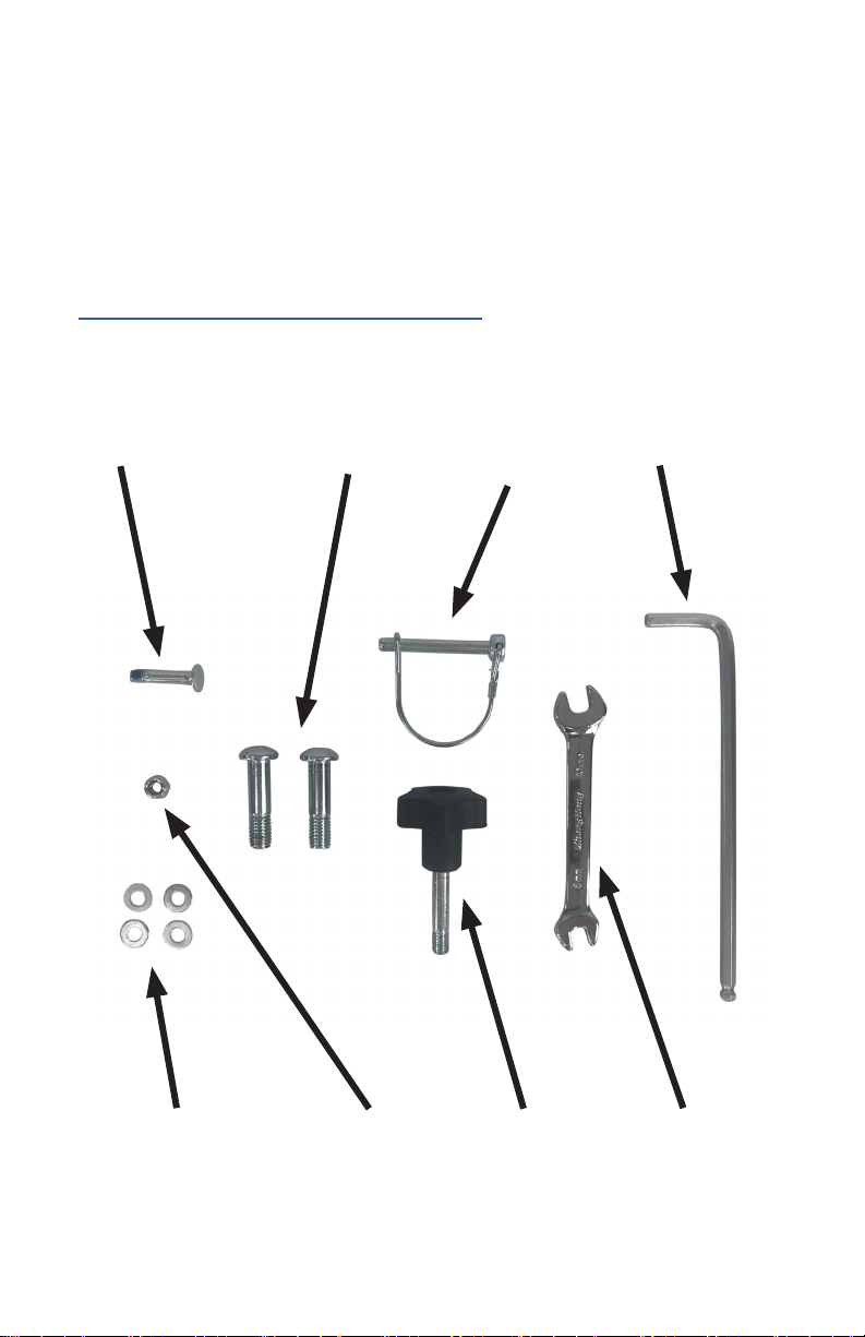
KneeRover® Deluxe Knee Cycle - Tools & Parts List:
The following tools and parts are included with your KneeRover® Deluxe Knee
Cycle. Please follow assembly instrucons for your specic KneeRover® model,
using the tools and parts provided.
Assembly videos for your KneeRover® model can also be found at:
hps://kneerover.com/pages/assembly-video
Tie Rod Bolt Front Axle Bolts Kneepad
Locking Pin
Allen Wrench
Tie Rod Washers (4) Tie Rod Nut Height Adjustment
Knob
Wrench for
Tie Rod Bolt
and Brake
Adjustment

KneeRover® Deluxe Knee Cycle Set Up Instrucons:
Please follow the step by step instrucons on the following pages to properly
assemble your KneeRover® scooter. The diagram below idenes the key
components of the scooter to aid with assembly.
Visit hps://kneerover.com/pages/assembly-video for assembly videos.
Weight capacity = 300 pounds
Height Adjustment
Knob
Hand Brake with Parking
Feature
Steering
Column
Brake Cable
7.5” Wheels
Rear Brake
Adjustable
Knee Plaorm
Quick Release
Lever
Front Alxe
Step 1: Front Axle Assembly
Please take your me to carefully complete all steps before operang your
new KneeRover® scooter. First, place the front axle with 7.5” wheels under the
scooter frame, ensuring the round bolts by the wheels are facing up (Top). Align
the axle and frame holes, insert front axle bolts and ghten completely using
the allen wrench provided (Boom). Make sure the welded nuts on the front
axle are facing towards the ground.
Round Bolt needs to face upInstall Front Axle Bolt through the top
hole and into the welded nut on the
boom
Tighten Front Axle Bolt with the
provided allen wrench
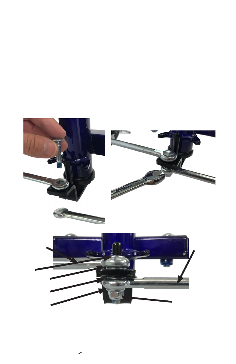
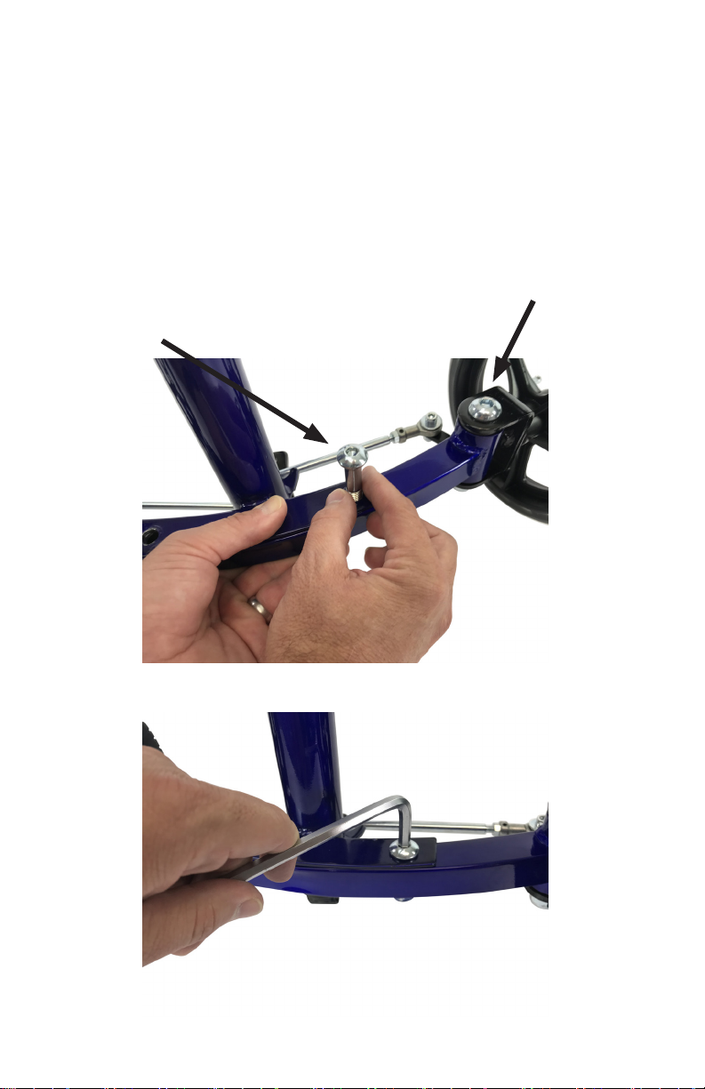
Step 2: Tie Rod Assembly
The e rod ends are already aached to the spindles/wheels. Bring the le e
rod (square hole) and place over the black guide and the right e rod (round
hole) under the black guide. Insert the bolt into the top e rod so the head of
the bolt is sing ush (Top Le). Next, insert the bolt through the washer and
black guide. Place another washer on the e rod bolt under the black guide
and then the bolt through the right e-rod round hole. Next, place two
washers onto the e-rod bolt from the boom and then the locking nut. Aer
the e rods are assembled, ghten the locking nut unl it barely touches the
boom washer (Top Right). Take care not to over ghten the locking nut, as this
could cause some resistence while turning the knee walker. Below is a picture
of a properly assembled Tie Rod (Boom).
Le Tie Rod Right Tie
Rod
Bolt
Washer (1)
Washer (1)
Washers (2)
Locking Nut
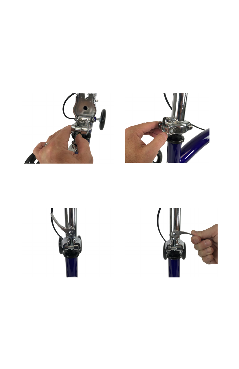
Step 3: Steering Column Assembly
Raise the steering column up by pushing the clamp lever to the le allowing the
column to raise all the way up (Top Le and Right). Raise the clamp lever
upward in to the “U” slot and ghten by turning it clockwise (Boom Le).
Finally, push clamp lever down rmly to secure the steering column (Boom
Right). Reverse these steps when needing to lower steering column for
transport.
Push pin to the le Raise steering column and
release the pin
Raise the clamp into the “U”
shaped slot
Push clamp down
rmly
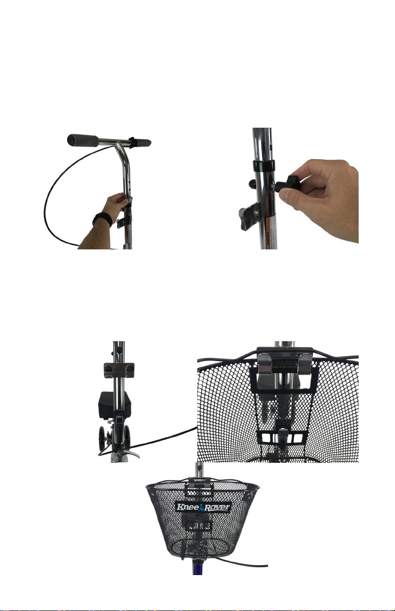
Step 4: Handle Bar Assembly
Please make sure the brake line is not twisted and the brake handle is facing
forward. Insert the handle bar into the steering column (Le). Raise the
handle bar to a comfortable posion and insert the height adjustment knob
into the hole and ghten (Right). We recommend the handle bar height to be
set approximately waist high.
Step 5: Basket Assembly
Locate the basket bracket on the front of the steering column (Top
Le). Place the rear basket holes over the bracket and push down (Top
Right). Your basket is now installed on the steering column (Boom).

Step 6: Knee Plaorm Assembly
The knee plaorm is designed to be used with either the right or le leg. Insert
the knee plaorm post into the receptacle tube (Top Le). Next, set the knee
plaorm at your desired height for use by inserng the locking pin through the
aligned holes (Top Right). We recommend that the knee on the knee plaorm
be at a 90 degree angle while the leg on the ground is straight. Finally, ghten
the clamp lever to secure the knee plaorm in place (Boom Le).
Insert Knee plaorm into the
receptacle tube
Insert the locking pin through the
aligned holes
Tighten and secure the clamp Properly assembled
kneepad

Brake and Parking Brake Operaon
Your KneeRover® knee walker comes equipped with a Brake Lock/Parking Brake.
To engage the brake, squeeze the brake lever on the handle bar. To apply the
parking brake, squeeze brake handle rmly and while squeezing the brake
handle press the silver buon to engage the lock. While sll holding the buon
down, release the brake handle and your parking brake will be set. To release
the lock, squeeze the brake handle again and the silver buon will pop up.
Unlocked Brake Locked Brake
Brake Adjustment
If there is ever a need to perform a brake adjustment, please follow these steps.
Locate the brake cable and spring at the rear of the scooter. Use a 10mm
wrench and loosen the nut (Le). Squeeze the spring together and pull the
brake cable down (Right). While holding the brake cable, reghten the nut.
You may also view the brake adjustment video by vising hps://kneerover.
com/pages/kneerover-maintenance-videos.
Table of contents
Other KneeRover Bicycle manuals


