Knight D Series User manual

w
D-SERIES
Servo Hoist
Maintenance and
Operation Manual
THIS MANUAL CONTAINS IMPORTANT INFORMATION REGARDING INSTALLATION, SAFETY, MAINTENANCE,
AND OPERATION OF THE KNIGHT GLOBAL SERVO HOIST AND SHOULD BE AVAILABLE TO ALL PERSONNEL
RESPONSIBLE FOR USING THE HOIST.
REV: 005_202112

KNIGHT D-SERIES SERVO HOIST OPERATION MANUAL
This manual provides important information for all personnel involved in the installation, operation
and maintenance of the Knight Global Servo Hoist. All personnel must read this document before
operating the equipment.
Every effort has been made to provide complete and accurate product information in this manual.
However, due to product improvements and changes, discrepancies and omissions may be
present. Visit our website at www.knightglobal.com for the updated information on all our
products.
It is the responsibility of the end user to exercise common sense and judgment when performing
the tasks described in this manual. If any procedure seems inaccurate, incomplete or unsafe
please put the equipment in a safe condition and contact Knight Global service department for
assistance. Knight Service department’s phone number is: (248) 375-7962.
Throughout this manual there are steps and procedures that if not performed correctly can result
in personal injury or equipment damage. The following signal words are used to identify the level
of potential hazard.
WARNING
Indicates a hazard which will cause severe injury, death or substantial
equipment damage.
CAUTION
Indicates a hazard which can or will cause injury or equipment damage.
NOTE
Notifies personnel of installation, operation or maintenance information
which is important but not hazard related.

KNIGHT D-SERIES SERVO HOIST OPERATION MANUAL
1.SAFETY ........................................................................................................................................................ 1
A.General Safety Precautions .............................................................................................................. 2
B.Safety Devices ................................................................................................................................... 3
Motor Holding Brake .................................................................................................................. 3
Overload Capacity Protection .................................................................................................... 3
Run-Stop Push Button ............................................................................................................... 3
Safety Drop Stop (SDS) Chain .................................................................................................. 3
2.INSTALLATION ........................................................................................................................................... 4
A.Introduction ........................................................................................................................................ 5
B.Initial Setup ........................................................................................................................................ 6
Step 1: Unpacking .................................................................................................................... 6
Step 2: System Assembly ......................................................................................................... 6
Step 2a) Servo Hoist Trolley Installation: ................................................................. 6
Step 2b) Safety Cable Installation: ........................................................................... 7
Step 2c) 19-pin Coil Cable Installation: .................................................................... 8
Step 2d) 4mm and 5mm Chain Installation: ............................................................. 9
Step 3: Power Supply to Servo Hoist ..................................................................................... 10
Step 4: Releasing the Run-Stop button .................................................................................. 10
Step 5: Control Handle Set-up ............................................................................................... 1 1
Step 6: Test Hoist Movement ................................................................................................. 11
Step 7: Back-Up Software ...................................................................................................... 11
Step 8: Software Adjustments (If necessary) ......................................................................... 12
3.OPERATION .............................................................................................................................................. 13
A.Principle of Operation ..................................................................................................................... 13
B.Model Number .................................................................................................................................. 13
C.Servo Hoist Control Configuration ................................................................................................ 14
D.Servo Hoist Functionality Modes ................................................................................................... 15
Run-Stop .................................................................................................................................. 15
Shut Down ............................................................................................................................... 15
Start Up .................................................................................................................................... 15
No Mode .................................................................................................................................. 15
Lift Mode .................................................................................................................................. 15
Float Mode ............................................................................................................................... 16
Fault Mode ............................................................................................................................... 16
4.MAINTENANCE ......................................................................................................................................... 17
A.CHAIN INSPECTION ........................................................................................................................ 17
4.1 Inspection Overview .......................................................................................................... 17
4.2 Use of Chain Safely in Any Application ............................................................................. 18
4.3 Determining the Frequency of Chain Inspections ............................................................. 19
4.3.1 Service Rating Load Criteria ................................................................................. 19
4.3.2 Service Class (Duty Cycle) .................................................................................... 19
4.4 Type of Inspections ........................................................................................................... 20
4.4.1 Frequent Inspection (Visual) ................................................................................. 20
4.4.1.1 What to Look for During a Frequent Inspection ...................................... 20
4.4.2 Periodic Inspection (Documented) ........................................................................ 21
4.4.2.1 Recommendations for Periodic Inspections ............................................ 21
4.4.2.2 Recommended Record Keeping for Periodic Inspections ...................... 23
4.4.3 Chain Lubrication:.................................................................................................. 24
4.4.4 Load Chain Replacement: ..................................................................................... 24

KNIGHT D-SERIES SERVO HOIST OPERATION MANUAL
B.PREVENTATIVE MAINTENANCE FOR KNIGHT SERVO HOIST .................................................. 25
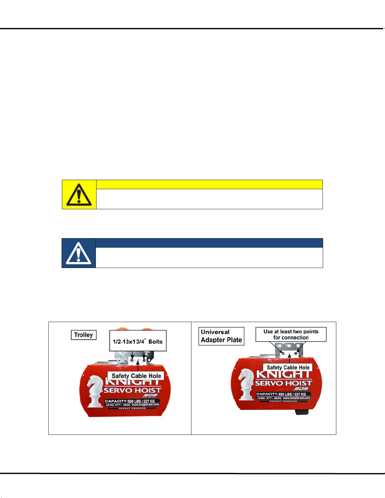
4.5 Servo Hoists Inspections ................................................................................................... 25
4.5.1 Recommendations for Frequent Inspections for Servo Hoists (Visual) ................ 25
4.5.2 Periodic Inspection (Documented) ........................................................................ 25
4.6 Load and Safety Drop Stop Chain Replacement (Normal Maintenance) ......................... 28
4.6.1 Resetting the Encoder Offset ................................................................................ 33
4.7 Broken Chain Replacement .............................................................................................. 34
5.SOFTWARE ............................................................................................................................................... 36
A.Getting Started ................................................................................................................................. 37
B.Connecting to a Servo Hoist .......................................................................................................... 38
C.Backing up the Knight Servo Hoist Software ............................................................................... 41
D.Loading New Hardware with Existing Software ........................................................................... 46
E.Review the Hoist’s Knight Servo Studio Software ....................................................................... 52
F.Accessing the Servo Hoist’s Fault Log ......................................................................................... 91
6.PARAMETER DESCRIPTIONS ................................................................................................................. 93
A.bPRM Parameter Array ................................................................................................................... 93
B.bSTS Status Array ........................................................................................................................... 97
C.iPRM Parameter Array ................................................................................................................... 103
D.iSTS Parameter Array .................................................................................................................... 103
E.dPRM Parameter Array ................................................................................................................. 104
F.dSTS Parameter Array .................................................................................................................. 104
G.tPRM Parameter Array .................................................................................................................. 105
H.fPRM Parameter Array .................................................................................................................. 105
I.fSTS Status Array .......................................................................................................................... 112
7.TROUBLESHOOTING ............................................................................................................................. 115
A.Troubleshooting Screens ............................................................................................................. 115
7.1) Unable to Connect ......................................................................................................... 115
7.2) Can't Enter Lift Mode screen ......................................................................................... 116
7.3) Can't Enter Float Mode screen ...................................................................................... 117
7.4) Can't Move Up screen ................................................................................................... 117
7.5) Can't Move Down screen .............................................................................................. 119
7.6) Slow Flashing Red Light screen .................................................................................... 120
7.7) Fast Flashing Red Light screen .................................................................................... 120
7.8) Flashing Green Light screen ......................................................................................... 122
7.9) Alternating Red/Green Lights screen ............................................................................ 123
7.10) Solid Red Light screen ................................................................................................ 124
7.11) Solid Green Light screen ............................................................................................. 124
7.12) Solid Blue Light screen ............................................................................................... 125
7.13) Solid Green/Blue Lights screen ................................................................................... 125
7.14) Motion Drift screen ...................................................................................................... 126
B.System Activity screens including Faults, Warnings and Error Codes................................ 127
7.15) System Status screen ................................................................................................. 127
7.16) Alarms / Warnings screen ........................................................................................... 128
C.Troubleshooting Inputs and Outputs .......................................................................................... 129
7.17) I/O Status screen ......................................................................................................... 129
D.Troubleshooting Chart .................................................................................................................. 130
8.SPARE PARTS LIST ............................................................................................................................... 131
9.DECOMMISSIONING OF A SERVO HOIST ........................................................................................... 132
10.KNIGHT’S PERFORMANCE WARRANTY ............................................................................................. 133

KNIGHT D-SERIES SERVO HOIST OPERATION MANUAL
SECTION 1
SAFETY 1
1. SAFETY
Knight Global cannot be aware of or provide for all the procedures by which the Servo Hoist operations or
repairs may be conducted and the hazards which may result from each method. If operation or maintenance
not specifically recommended by Knight Global is conducted, it must be ensured that product or personnel
safety is not endangered by these actions. If not sure of an operation or maintenance procedure or step,
personnel should place the Servo Hoist in a safe condition and contact a supervisor and/or the Knight Global
service department for technical support. Modifications to upgrade, re-rate or otherwise alter this equipment
shall be authorized only by the original equipment manufacturer.
If a below-the-hook lifting device or sling is used with the Servo Hoist, refer to ANSI/ASME B30.9 “Safety
Standard for Slings”, or ANSI/ASME B30.20 “Safety Standard for Below-the-Hook Lifting Devices”.
Electrical equipment described in this manual are designed and built-in compliance with ANSI/NFPA 70,
“National Electrical Code”. It is the responsibility of the system designer, system manufacturer, crane or rail
manufacturer, installer, and user to ensure that the installation and associated wiring of the Servo Hoist and
components are in compliance with ANSI/NFPA 70, and all applicable Federal, State and Local Codes.
Hazardous voltages are present in the Servo Hoist and components. Only properly trained and competent
personnel should perform inspections or repairs on the Servo Hoist or accessories. Prior to performing any
maintenance (mechanical or electrical) on the Servo Hoist, de-energize (disconnect) the main switch
supplying power to the Servo Hoist. Lock out the power supply following standard plant procedures.
Ensure that the installation, inspection, testing, maintenance and operation are in compliance with
ANSI/ASME B30.16 “Safety Standard for Overhead Hoists”, OSHA Regulations, ANSI/NFPA 70, National
Electric Code, and applicable ANSI/ASME standards. This is the responsibility of the owner/operator.
All personnel that will install, operate, inspect, test or maintain the hoist should read this manual and be
familiar with all applicable portions of the referenced standards.
If clarification of any information in this manual or additional information is required, contact Knight Global.
Do not install, operate, inspect, test or maintain the hoist unless all information is understood.

KNIGHT D-SERIES SERVO HOIST OPERATION MANUAL
SECTION 1
SAFETY
2
A. General Safety Precautions
Do not operate the Servo Hoist before reading this technical manual.
Allow only personnel trained in safety and operation of this Servo Hoist to operate the Servo Hoist.
If the Servo Hoist is locked out or a “DO NOT OPERATE” sign is on the Servo Hoist or controls, do
not operate the Servo Hoist until the lock or sign is removed by designated personnel.
Do not use the Servo Hoist if the hook’s safety latch has been sprung or broken.
If the Servo Hoist utilizes a hook, ensure the hook’s safety latch is engaged before operating the
hoist.
Before each shift or prior to use, inspect the Servo Hoist in accordance with the procedures defined in
the Maintenance section of this manual.
Never place your hand or fingers inside the throat area of a hook.
Never operate a Servo Hoist with twisted, kinked or damaged chain.
Only operate a Servo Hoist when the chain is centered over the hook. Do not “side pull” or “yard” the
chain.
Do not force the hook into place by hammering.
Ensure the load is properly seated in the saddle of the hook.
Never run the chain over a sharp edge.
Pay attention to the load at all times when operating the Servo Hoist.
Ensure no personnel are in the path of the load.
Do not lift the load over personnel.
Never use a Servo Hoist for lifting or lowering people.
Do not allow anyone to stand on a suspended load.
Do not swing a suspended load.
Never leave a suspended load unattended.
Never cut or weld a suspended load.
Do not operate a Servo Hoist if the chain is jumping, jamming, overloading or binding.
Do not operate a Servo Hoist if it is generating excessive noise.
Avoid collisions or bumping of the Servo Hoist.
Do not operate a Servo Hoist when damaged or malfunctioning.
Do not remove load or handling device until tension is released from the chain.
Discontinue operation of a Servo Hoist after multiple unresolved faults. A system fault would be
signified by the Red light on the Run-Stop button continuously flashing or the Run-Stop button
having to be repeatedly reset.

KNIGHT D-SERIES SERVO HOIST OPERATION MANUAL
SECTION 1
SAFETY 3
B. Safety Devices
Motor Holding Brake
A motor holding braking system engages and holds the vertical axis in place in the event of a power outage or
when the Run-Stop button is pressed.
Overload Capacity Protection
Protects the equipment and prevents the operator from lifting or moving more weight than the system is rated
for. If the load weight exceeds the programmed capacity, the hoist will not lift any further until the excess
load is removed. Downward motion is permitted when overloaded to allow the user to safely set the weight
back down on a stable surface.
Run-Stop Push Button
If an operator needs to stop motion immediately, the operator pushes the Run-Stop button. The
system will not function until it is reset. To reset the system from the Run-Stop condition, the operator turns
the button clockwise to release it from the depressed position. All virtual limits and programs remain intact.
Safety Drop Stop (SDS) Chain
All Standard units have a Safety Drop Stop (SDS) chain included. The SDS Chain moves up and down the
vertical axis with the load chain. It provides load stabilization in the event of a catastrophic load chain
failure. This unique feature has a US Patent NO. 10,099,904 awarded as of 2018.

KNIGHT D-SERIES SERVO HOIST OPERATION MANUAL
SECTION 2
INSTALLATION
4
2. INSTALLATION
Prior to installation, visually inspect the Servo Hoist for signs of damage or missing parts.
CAUTION
Prior to installation, the chain must be lubed using a SAE 50 to 90 EP oil.
Follow the procedure detailed in section 4.4.3 “Chain Lubrication”
of this manual.
Knight Global recommends the use of Demag Chain Grease.
The part number of the Demag Chain grease tube is 665 009 44.
CAUTION
Prior to placing this unit into service, the owners and user are advised
to examine specific local and/or other regulations, including ANSI and
OSHA regulations that may apply to the use of this product.
WARNING
A falling load can cause injury or death. Before installing this hoist read
the “Safety” section of this manual.
Follow all procedures in this section for installation and set-up of the Servo Hoist.
Retain all product information supplied with the Servo Hoist for future reference.
Ensure that the supporting structure is able to support the weight of the system and load. The structure
should be able to support 300 percent of the combined weight of the Servo Hoist and load. Do not use a
supporting structure that tilts the Servo Hoist to one side or the other.
For safe and proper installation into a rail system, refer to the installation manual provided by the rail system
manufacturer.
When installation is complete and prior to placing the Servo Hoist into operation, inspect the Servo Hoist
following the instructions in section 4.4.2.1 “Recommendations for Periodic Inspections” in the
“Maintenance” portion of this manual.

KNIGHT D-SERIES SERVO HOIST OPERATION MANUAL
SECTION 2
INSTALLATION 5
A. Introduction
Prior to installing and operating the Knight Servo Hoist, all operators using this device should be familiar with
the main components of the lifting system. (Refer to Figure 2-1)
Servo Hoist: The Servo Hoist assembly is a powered lifting device. The upper drive assembly contains the
servo motor with holding brake, gearbox, servo drive, power contactor, 24 VDC Power Supply, regen board,
chain bucket, chain guide assembly, and AC Plug.
Coiled Cable Assembly: In most cases, a 19-pin coil cable carries signals from the control handle to the
Servo Hoist. Some examples are: Analog load cell voltages, digital inputs and outputs including direction
commands, Lift Mode, Float Mode, and Run-Stop signals. In some cases, a 19-pin straight cable carries
some or all of these signals to the Servo Hoist.
Control Handle: The main interface between the operator and the lifting device. The handle can be an
inline handle, a fixture handle, or a discrete up / down handle.
Figure 2-1
Trolley or Universal
Adapter Plate
Safety
Cable
19-pin
Coil Cable
Chain Nest
Control Handle
(Inline)
Load Shackle
Location
Servo Hoist

KNIGHT D-SERIES SERVO HOIST OPERATION MANUAL
SECTION 2
INSTALLATION
6
B. Initial Setup
Step 1: Unpacking
1a) Unpack the Servo Hoist. Lift the hoist carefully out of packaging.
1b) Keep the accompanying documents with the hoist or near the site of operation.
Step 2: System Assembly
Knight Servo Hoists are typically delivered pre-assembled; if not, read the following sections.
2a) Servo Hoist Trolley Installation
2b) Safety Cable Installation
2c) 19-pin Coil Cable Installation
2d) 4mm and 5mm Chain Installation
Step 2a) Servo Hoist Trolley Installation:
Prior to installation visually inspect the trolley for signs of damage or missing parts.
1) Slide the trolley or adapter plate into the trolley mounting plate on top of the Servo Hoist.
(Refer to Figure 2-2)
CAUTION
Ensure that there is a (2) two-point connection when using the universal
adapter plate to hang the hoist from a structure. (Refer to Figure 2-3)
2) Insert the (2) two ½-13x1¾” (grade 8 or better) socket head cap screws (SHCS) and
(2) two washers.
NOTE
The trolley should be mounted offset of the load distribution.
3) Secure the (2) two SHCS with (2) two ½-13 reverse lock nuts. As each bolt is tightened, the
reverse lock nut will get drawn into its slot and get trapped there.
4) Install the safety cable through the servo trolley or adapter and the trolley mounting plate.
(Refer to Step 2b “Safety Cable Installation”)
5) Roll hoist into rail system.
Figure 2-2
Figure 2-3

KNIGHT D-SERIES SERVO HOIST OPERATION MANUAL
SECTION 2
INSTALLATION 7
Step 2b) Safety Cable Installation:
1) Slide thimbles together. (Refer to Figure 2-4)
2) Slide (2) two Crosby cable clamps onto the cable.
3) Loop the end of cable around thimble and run the end through the Crosby clamps.
The cable saddle (forged part) rests on the “live” (longer) end of the cable.
The U-bolt rests on the “dead” (shorter) end of the cable. (Refer to Figure 2-5)
4) Tighten each nut on a single clamp, alternating sides. Repeat this procedure on the other clamp.
Each nut should be tightened to a minimum of 15 ft-lbs.
5) Follow the steps below for trolley or adapter plate.
6) Insert cable through the center hole on the trolley bracket which is attached to the hoist and place
(2) two Crosby clamps on the other end of the cable. (Refer to Figure 2-6)
7) Secure the (2) two Crosby clamps snug to the thimble, repeating step 3.
8) Install the cable so that the Servo Hoist has a drop of not more than 1 in. [2.54 cm].
9) Trim excess cable and tape ends of cable to prevent fraying. (Refer to Figure 2-6)
Figure 2-4
Fi
g
ure 2-5
Figure 2-6
Figure 2-7
“U-Bolt”
“Cable Saddle”
Center Hole
Crosby Cable Clamp

KNIGHT D-SERIES SERVO HOIST OPERATION MANUAL
SECTION 2
INSTALLATION
8
Step 2c) 19-pin Coil Cable Installation:
1) Ensure power is removed from hoist.
2) Slide the 19-pin coil cable upward over the chain and into the clamping assembly.
3) Secure the (4) four M6 nuts onto the bolts that pass through the clamping assembly from the
bottom of the Servo Hoist. (Refer to Figure 2-8)
4) Connect the 19-pin connector to the bottom of the Servo Hoist. (Refer to Figure 2-9)
5) Seat both chains into the control handle’s chain nest. Secure both of the chain’s retaining bolts
through the provided holes in the chain nest.
(Refer to Step 2d “4mm and 5mm Chain Installation”)
6) Loosen the (2) two M4 screws holding the 19-pin receptacle and slide it out of the control
handle’s housing. (Refer to Figure 2-10)
7) Connect the 19-pin connector to the receptacle, slide it back into the control handle’s housing
and secure the (2) two M4 screws. (Refer to Figure 2-11)
8) Secure the (2) two M6 bolts for each of the handle coil cable clamping rings located on top of the
control handle. (Refer to Figure 2-11)
Figure 2-8
Figure 2-9
Figure 2-10
Fi
g
ure 2-11
19-Pin Connector
19-Pin Connector
Clamping
Rings
M6 Nuts
M4 Bolts
(M3 Allen
Wrench)
Clamping
Assembly

KNIGHT D-SERIES SERVO HOIST OPERATION MANUAL
SECTION 2
INSTALLATION 9
Step 2d) 4mm and 5mm Chain Installation:
CAUTION
DO NOT CUT CHAIN TO SHORTEN IT! The chain will be reeled into the
hoist in Section 2, Step 5 “Control Handle Set-up”.
1) Thread both chains through the coil cable.
2) Place the load chain into the top portion of the chain nest and insert the bolt provided thru chain
nest in front of load chain’s last link. An M4 Allen wrench is required if the servo’s capacity is
250 or 500lbs. Otherwise, both the M4 and then M5 Allen wrenches will be required.
(Refer to Figure 2-12)
3) Ensure that both chains are parallel with no twists from the gear box down to the chain nest.
4) Install the last link of the Safety Drop Stop (SDS) chain into the lower portion of the chain nest in
front of the load chain. Ensure that the SDS chain is kept parallel to the load chain.
5) Install the bolt provided into the bottom bolt hole in the chain nest and through the last link in the
SDS chain. (Refer to Figure 2-13)
6) Ensure that the large O-ring is fitted into the groove of the chain nest and the small O-ring is just
above the chain nest but below the safety chain ID tag. (Refer to Figure 2-14)
7) Figure 2-15 shows the completed installation of both chains into the chain nest.
Figure 2-12
Figure 2-13
Figure 2-14
Figure 2-15
Chain Nest
M4 or M5
Allen
Wrench
M4 or M5
Allen
Wrench
Small O-ring
Large O-ring
Load Chain
Safety Chain
Safety Chain
ID Tag

KNIGHT D-SERIES SERVO HOIST OPERATION MANUAL
SECTION 2
INSTALLATION
10
Step 3: Power Supply to Servo Hoist
Prior to installation visually inspect the Servo Hoist for signs of damage or missing parts.
Power Requirements: 240 VAC 20 FLA Single Phase 50/60 Hertz is Standard. Call a Knight Representative
to obtain the correct power requirements for your system.
Refer to system specific documentation for any special power requirements.
1) The Servo Hoist power is connected by a twist lock plug (Refer to Figure 2-16: Standard) or fed
by a hard-wired circuit, provided by end user (Refer to Figure 2-17: CE Compliant).
2) The red light on the Run-Stop button will illuminate when power is provided to the
Servo Hoist system.
Step 4: Releasing the Run-Stop button
The Run-Stop button is engaged for shipping purposes.
1) Turn Run-Stop button a quarter of a turn clockwise to release the Run-Stop and wait for red light
to turn off. (Refer to Figure 2-18.)
2) Please, refer to the Run-Stop mode functionality in section 3.D. “Servo Hoist Functionality
Modes” of this manual for more information.
Figure 2-18
Figure 2-16: Standard
Figure 2-17: CE Compliant
Twist Lock Plug

KNIGHT D-SERIES SERVO HOIST OPERATION MANUAL
SECTION 2
INSTALLATION 11
Step 5: Control Handle Set-up
Inline Handle setup:
1) Hold the inline handle and trigger with one hand, and hold the chain away from the inline handle
with other hand. (Refer to Figure 2-19)
2) Apply upward pressure on inline handle until the green light flashes.
3) Once green light starts flashing, release the inline handle and the GREEN light will illuminate.
4) Grasp the inline handle and apply upward pressure until the chain starts feeding into the hoist.
Continue this until the inline handle is hanging vertically from the hoist at a comfortable height.
Figure 2-19
NOTE
A continuously flashing GREEN light indicates a safe start activation
fault. The system is sensing commanded motion during the Power-Up
sequence.
Remedy
Analog Handle: Release the handle and verify that the GREEN light
illuminates solid. If the GREEN light still flashes after the handle is
released, refer to section 7. “Troubleshooting”.
Step 6: Test Hoist Movement
Test the Servo Hoist movement by applying upward and downward pressure on the inline handle. The system
should move up and down freely.
Step 7: Back-Up Software
Knight Servo Hoists are pre-programmed prior to delivery. It is a good practice to back-up this software
before initial operation. Refer to the section 5. ‘Software’ portion of this manual for instructions to connect to
the Servo Hoist and to back-up the software.

KNIGHT D-SERIES SERVO HOIST OPERATION MANUAL
SECTION 2
INSTALLATION
12
Step 8: Software Adjustments (If necessary)
After making a back-up of the software in step 7, it may be necessary to adjust certain parameters in the
software to ensure that the servo performs correctly for a specific application. Refer to the following first-
time adjustments in section 5. ‘Software’.
Verify that the Float load cell is zeroed correctly, see Section 5 E. Step 36
Verify the hoist’s maximum allowed weight. This is also known as the Up Stop weight of the hoist.
See Section 5 E. Step 36
Verify the hoist’s minimum weight. This is also known as the Down Stop or pay out weight of the
hoist. See Section 5 E. Step 36
Verify the hoist’s fixture weight, see Section 5 E. Step 39

KNIGHT D-SERIES SERVO HOIST OPERATION MANUAL
SECTION 3
OPERATION 13
3. OPERATION
A. Principle of Operation
The Servo Hoist system receives a command to move up or down along the “Z” axis from any input force
applied to the handle.
B. Model Number
The Servo Hoist model number* designates the Servo Hoist type and its specifications. (Refer to Figure 3-1)
The first set of letters indicate the type of Servo Hoist.
The numbers following the Servo Hoist Type prefix letters reference the system’s rated capacity.
“D” designates that this is a D-Series hoist.
“S” designates our Safety Drop Stop feature.**
The next (3) three numbers indicate the voltage
The following number indicates the phase of the system.
The last (3) three digits are a Knight control servo code.
The hoist’s model number* and serial number can be found on the Knight identification label located on the
Servo Hoist.
Fi
g
ure 3-1 Servo Hoist Model Number Example
* For all models and specifications, refer to the website: https://knightglobal.com/product/d-series-servo-hoist/
** All Knight Servo Hoists include a Safety Drop Stop chain that travels with the load chain to support
the fixture in the event of a catastrophic load chain failure.

KNIGHT D-SERIES SERVO HOIST OPERATION MANUAL
SECTION 3
OPERATION
14
C. Servo Hoist Control Configuration
Figure 3-2: D-Series Servo Hoist

KNIGHT D-SERIES SERVO HOIST OPERATION MANUAL
SECTION 3
OPERATION 15
D. Servo Hoist Functionality Modes
Run-Stop
Step 1. Press the RUN-STOP button, located on the Operator Control Interface (OCI) module.
Motion is stopped and the motor’s holding brake is set.
The Run-Stop button will illuminate red.
Step 2. Reset the RUN-STOP button by twisting it a quarter of a turn clockwise.
Shut Down
Step 1. Press the RUN-STOP button, located on the Operator Control Interface (OCI).
Step 2. Follow the warning labels on the Servo Hoist and disconnect the power supplied to the unit.
Start Up
Step 1. Connect the power supply to the unit.
The hoist will power up and the OCI’s RED indicator will illuminate.
Step 2. Reset the RUN-STOP button by twisting it a quarter of a turn clockwise.
The OCI’s RED and GREEN indications will briefly flash when the system is ready to
function.
The unit will then default to No Mode: the OCI’s GREEN, BLUE, and RED indicators will
turn off.
No Mode
When the Servo Hoist powers up the unit will be in this energy saving mode. No mode can also be triggered
if the hoist is inactive for set time period. By default, this time out feature is turned off. When in No Mode,
the holding brake will engage and power will be removed from the motor. When the unit is in No Mode, the
OCI’s GREEN, BLUE, and RED indicators will be off.
Lift Mode
Press the GREEN (Lift) button to place the Servo Hoist into Lift Mode.
The GREEN (Lift) indicator will illuminate.
NOTE
A continuously flashing GREEN light indicates a safe start activation
fault. The system is sensing commanded motion during the Power-Up
sequence.
Remedy
Analog Handle: Release the handle and verify that the GREEN light
illuminates solid. If the GREEN light still flashes after the handle is
released, refer to section 7. “Troubleshooting”.
Step 1. Squeeze the Enabling Trigger.
Step 2. Apply force to the handle in the desired direction of travel (upward or downward).
The travel speed of the fixture is proportional to the force applied to the handle.
NOTE
If the hoist is in No Mode and a lift command is given to the system via
the inline handle, the hoist will automatically go into Lift Mode.

KNIGHT D-SERIES SERVO HOIST OPERATION MANUAL
SECTION 3
OPERATION
16
Float Mode
Step 1. Press the BLUE (Float) button to place the Servo Hoist into Float Mode.
When the BLUE button is pressed, a snapshot is taken of the load that is attached to the
end of the hoist (i.e. the system records the weight suspended from the fixture).
The BLUE (Float) indicator will illuminate.
Step 2. Apply pressure to the top of the part to move it down or lift up on the part to move it up.
Do not use the lift controls to move the part as this will place the hoist back into Lift Mode.
WARNING
An operator should never be able to release a load while in Float mode.
The operator must switch to Lift mode in order to release a load.
NOTE
If the Knight controls team programmed the hoist, it will never release or
unclamp a part while it is in Float mode. The hoist will have to be
switched to Lift mode fo
r
a part to be released or unclamped.
To change from Float Mode to Lift Mode, follow any of the steps below:
Operate the lift controls. The hoist will automatically change to Lift Mode and then it will move up or
down.
Press the GREEN (Lift) push button and the unit will change into Lift Mode.
Allow the Float Mode Timeout timer to expire. This timer is set at the factory to 0ms of non-use,
a value of 0 turns the timeout feature OFF. To change this timer, refer to
section 6G. ‘tPRM Parameter Array’ in the parameter descriptions section.
NOTE
The part must be picked up while the hoist is in Lift Mode and then the
operator may place the Servo Hoist into Float Mode.
NOTE
Do not rest your hand on the part when pressing the Float push button.
This can cause a bias or an incorrect zero value measurement to be
p
r
ocessed and ma
y
cause unintended movement.
NOTE
Use of the Lift Mode controls will prevent the unit from remaining in or
changing to Float Mode.
Fault Mode
The Red light will flash.
Step 1. Press the RUN-STOP button, located on the Operator Control Interface (OCI).
Motion is stopped and the motor’s holding brake is set.
The RUN-STOP button will illuminate red.
Recovery:
Step 1. Correct the situation that caused the fault.
Refer to section 7.B. “System Activity screens including Faults, Warnings and Error Codes”
for a list of common faults.
Step 2. Follow the Start Up procedure to restore power to the unit.
Table of contents
Popular Chain Hoist manuals by other brands

Asist
Asist AE8H75DN Instructions for use

POWERTEX
POWERTEX PLC user manual

Yale HOISTS
Yale HOISTS PSB-A Series Operating, Maintenance & Parts Manual

Pelsue
Pelsue 309 Operating and maintenance instructions

Fraco
Fraco SEH Series operating manual

Elephant
Elephant YII-25 YA-50 Instruction manual and safety instructions

Verlinde
Verlinde STAGEMAKER SL10 1004 M2 A D8+ manual

William Hackett
William Hackett L4 manual

POWERTEX
POWERTEX PCB-S1 Instructions for use

CM
CM Hurricane Mini 360 Operating, Maintenance & Parts Manual

HADEF
HADEF 24/12 Installation, operating, & maintenance instructions

Comeup
Comeup WK-100H Installation instruction