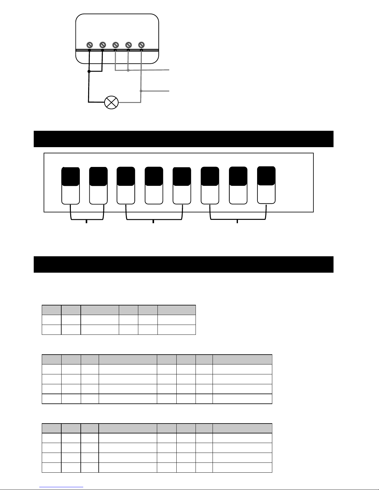
DIP SWITCH LAYOUT
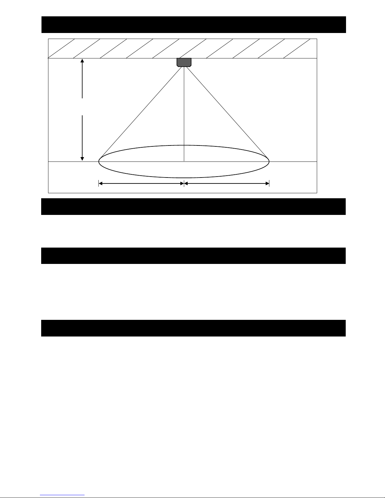
DISTANCE SETTING
• Switch on power supply and check for correct operation.
Note: We recommend that mounting height of between 1.8 to 2.5m. The table below shows
sensitivity distance in ideal conditions.
This can be set to ‘on
all the time (24hrs)’
or to a specific
lux level
Time setting
Lighting control settings
Note: Switch on is Position I and off is Position 0
Fig 2
Fig2
• Switchonpowersupplyandcheckforcorrectoperation.
DIPSWITCHLAYOUT
Note:SwitchonisPositionIandoffisPosition0
Distancesetting
Note:Werecommendthatmountingheightofbetween1.8to2.5m.Thetablebelowshowssensitivitydistanceinideal
conditions.
Lightcontrolsetting
Thiscanbeadjustedfromonallthetime(24hr)oronataspecificluxlightinglevel
OS0010
Theseinstructionsshouldbereadcarefullyandretainedafterinstallationbytheenduserforfuturereferenceand
maintenance.
Theseinstructionsshouldbeusedtoaidinstallationofthefollowingproduct:
OS0010
SAFETY
• Installationofthissensorshouldonlybecarriedoutbyaqualifiedelectricianorcompetentpersontothe
latestBuildingandcurrentIEEWiringRegulations(BS7671)
• Pleaseisolatemainspriortoinstallation/maintenance
• Checkthetotalloadonthecircuit(includingwhenthisluminaireisfitted)doesnotexceedtheratingofthe
circuitcable,fuseorcircuitbreaker
• PleasenotetheIP(IngressofProtection)ratingofthisluminairewhendecidingthelocationforinstallation
• ThisproductisClassIIdoubleinsulated
• ThisproductisIP20rated
INSTALLATION
• Providepowertotherequiredpointofinstallation.SuitableIPratedjunctionboxesshouldbeusedwhere
required
• Werecommendamountingheightof1.8mto2.5m
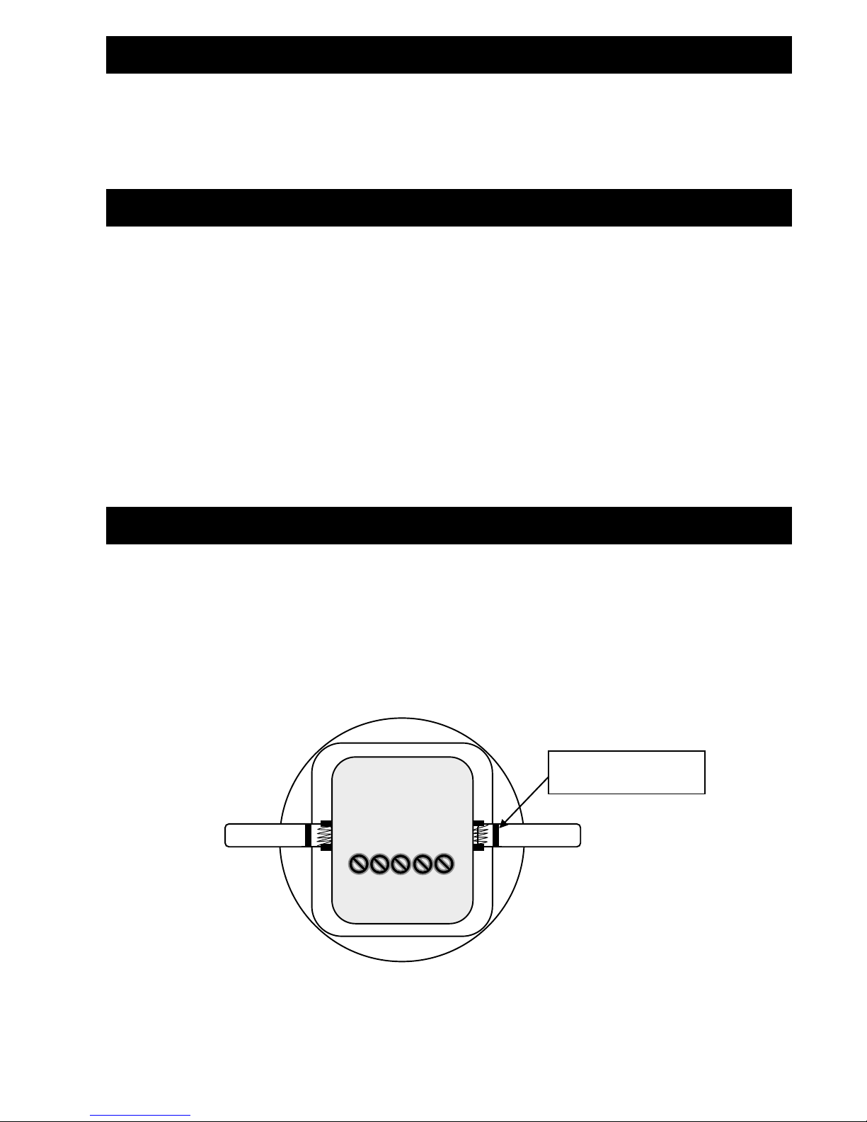
• Removethefrontcoverwiththeuseofaslottedscrewdriver(seeFig1)toaccessthedipswitches
Fig1
• Connectthesensortotheluminaireandmainssupply(viaterminalconnector)ensuringthecorrectpolarityis
observed.SeeFig2forthewiringdiagram(Live(brown),Neutral(blue)andSwitchedLive(L’))
L’L’LLN
L’L’LLN
Placeslottedscrewdriver
atthispointandtwist