WARNING
GENERAL
• Mark the location of the fixing holes, and
drill the holes ensuring not to infringe with
any joists, gas / water pipes or electrical
cables
• Feed the cable via the cable entry point on
the rear of the luminaire
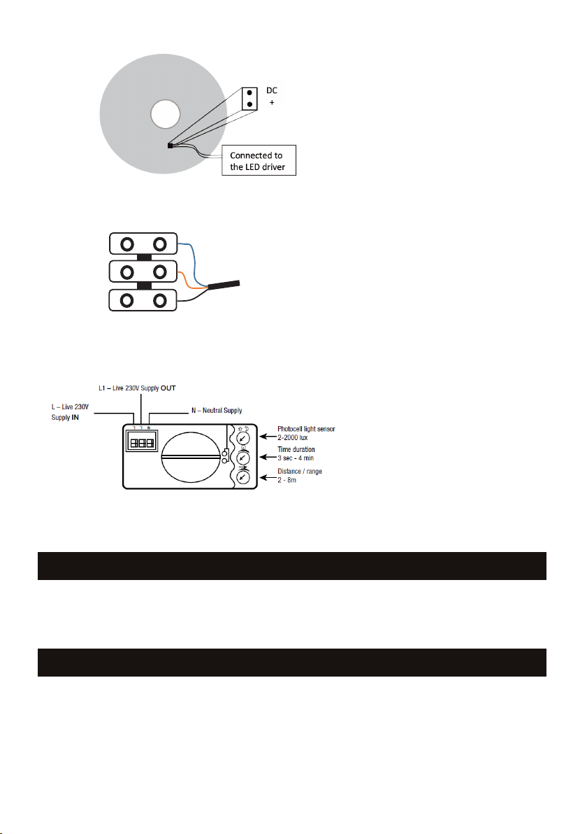
• Connect the Live (brown), Neutral (blue) to
the terminal block (see Fig 4)
• The additional terminal labelled
Slave Live is available to enable
the sensor to power additional
luminaires.
• See Fig 5 for sensor setup
This luminaire must be disconnected from the circuit if subjected to any high voltage or insulation
resistance testing. Irreparable damage will occur if this instruction is not followed.
The luminaire should be recycled in the correct manner when it reaches the end of its life. Check
local authorities for where facilities exist.
Clean with a soft dry cloth only, do not use aggressive cleaning products or solvents which may
damage the luminaire.
3
•Remove the LED plate and disconnect from the driver (via the DC socket) See Fig 3
Fig 3
•Mark the location of the fixing holes, and drill the holes ensuring not to infringe with any joists, gas / water pipes
or electrical cables
•Feed the cable via the cable entry point on the rear of the luminaire
•Connect switched Live (brown), Neutral (blue) to the terminal block (see fig 4)
Fig 4
•The additional terminal labelled Slave Live is available to enable the sensor to power additional luminaires.
•See Fig 5 for sensor setup
•Reconnect the LED plate to the driver (via the DC socket)
•Fasten the 3 LED plate screws
Connected to
the LED driver
Fig 3
Fig 4
Fig 5
• Reconnect the LED plate to the
driver (via the DC socket)
• Fasten the 3 LED plate screws
• Reattach the diffuser by rotating
clockwise
• Switch on and check for correct
operation