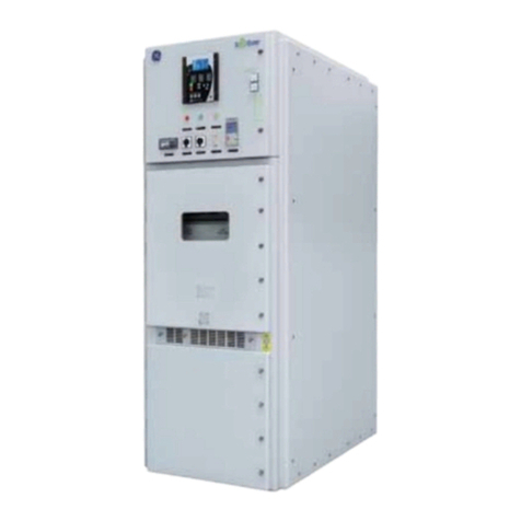
GE SecoGear User guide

DET-882 Application and Technical Guide
SecoGear
$ZE $ZE8444MecP[-R[PS Switchgear
GE Energy Connections
Industrial Solutions

©2016 General Electric All Rights Reserved i
HAZARD CLASSIFICATIONS
The following important highlighted information appears
throughout this document to warn of potential hazards or
to call attention to information that clarifies a procedure.
Carefully read all instructions and become familiar with the
devices before trying to install, operate, service or maintain
this equipment.
DANGER
Indicates a hazardous situation that, if not avoided, will
result in death or serious injury.
WARNING
Indicates a hazardous situation that, if not avoided, could
result in death or serious injury.
CAUTION
Indicates that if the hazard is not avoidedcould result in
minor or moderate injury.
NOTICE
Is used to notify of practices not related to personal injury.
TRADEMARKS
SecoGear® Seco RMU®
Seco Cube® SecoBloc®
SecoVac® VB2+ Multilin®
All third party trademarks are the property of their
respective owners.
WARRANTY
This document is based on information available at the
time of its publication. While efforts have been made to
ensure accuracy, the information contained herein does
not cover all details or variations in hardware and software,
nor does it provide for every possible contingency in
connection with installation, operation, and maintenance.
Features may be described herein that are not present in
all hardware and software systems.
GE Industrial Solutions assumes no obligation of notice to
holders of this document with respect to changes
subsequently made. GE Industrial Solutions makes no
representation or warranty, expressed, implied, or
statutory, with respect to, and assumes no responsibility
for the accuracy, completeness, sufficiency, or usefulness
of the information contained herein.
No warrantees of merchantability or fitness for purpose
shall apply.
Contact your local sales office if further information is
required concerning any aspect of SecoGear switchgear
and SecoVac VB2+ breaker operation or maintenance.

SecoGear Medium-voltage Switchgear Application and Technical Guide DET-882
ii ©2017 General Electric All Rights Reserved
TABLE OF CONTENTS
SECTION 1. SecoGear Switchgear Concepts and Basic Configurations......................................................................................1
SecoGear Metal-clad Switchgear...............................................................................................................................................................................................1
Switchgear Standards......................................................................................................................................................................................................................3
Underwriters Laboratories, Inc. (UL)....................................................................................................................................................................................3
Service Conditions........................................................................................................................................................................................................................3
Temperature................................................................................................................................................................................................................................3
Humidity........................................................................................................................................................................................................................................3
Altitude...........................................................................................................................................................................................................................................3
Applicable Industry Standards...............................................................................................................................................................................................3
Modular Construction and Typical Sectional Views.........................................................................................................................................................3
Modular Compartments............................................................................................................................................................................................................3
Rollout Configurations................................................................................................................................................................................................................5
Two-High Breaker and Auxiliary Stacking.......................................................................................................................................................................6
SECTION 2. Circuit Breaker Selection.............................................................................................................................................. 10
Circuit Breaker Ratings..................................................................................................................................................................................................................10
Selection Considerations..............................................................................................................................................................................................................10
Circuit Voltage..............................................................................................................................................................................................................................10
System Frequency ....................................................................................................................................................................................................................10
Short-Circuit Current................................................................................................................................................................................................................10
Closing and Latching Current..............................................................................................................................................................................................11
Continuous Current...................................................................................................................................................................................................................11
Rated Interrupting Time..........................................................................................................................................................................................................11
Duty Cycle......................................................................................................................................................................................................................................11
Special Switching Applications.................................................................................................................................................................................................11
Automatic Transfer...................................................................................................................................................................................................................11
Capacitor Switching..................................................................................................................................................................................................................12
Service Conditions...........................................................................................................................................................................................................................12
Usual Service Conditions........................................................................................................................................................................................................12
Unusual Service Conditions..................................................................................................................................................................................................12
Abnormal Temperature......................................................................................................................................................................................................12
Temperature Rise...................................................................................................................................................................................................................12
High Altitude.............................................................................................................................................................................................................................12
Breaker Accessories .......................................................................................................................................................................................................................13
Breaker Lift Truck.............................................................................................................................................................................................................................13
Related Circuit Breaker References........................................................................................................................................................................................14
Typical Breaker Device Internals.............................................................................................................................................................................................16
SECTION 3. Control Power Equipment............................................................................................................................................ 18
Control Power Requirements.....................................................................................................................................................................................................18
Breaker Close and Trip Considerations..........................................................................................................................................................................18
Breaker Tripping .........................................................................................................................................................................................................................18
DC Battery Trip........................................................................................................................................................................................................................19
SecoVac Autocharge Capacitor Trip Device............................................................................................................................................................19
Direct Acting Undervoltage Trip Device.....................................................................................................................................................................19
Breaker Closing...........................................................................................................................................................................................................................19
Indicating Lamps........................................................................................................................................................................................................................20
Relaying................................................................................................................................................................................................................................................20
Excitation Power...............................................................................................................................................................................................................................20
Other Loads.........................................................................................................................................................................................................................................20
Control Power Source Selection...............................................................................................................................................................................................21
DC Control Power Equipment..............................................................................................................................................................................................21
Battery Systems.........................................................................................................................................................................................................................21
Lead-Acid Batteries..............................................................................................................................................................................................................21
Nickel-Cadmium Batteries................................................................................................................................................................................................21

DET-882 SecoGear Medium-voltage Switchgear Application and Technical Guide
©2017 General Electric All Rights Reserved iii
Battery Capacity and Sizing.................................................................................................................................................................................................21
Battery Chargers.........................................................................................................................................................................................................................22
AC Control Power Equipment.....................................................................................................................................................................................................23
Application......................................................................................................................................................................................................................................23
Selection..........................................................................................................................................................................................................................................23
Guide to Estimating Heat Loss...................................................................................................................................................................................................24
SECTION 4. System and Equipment Protection.............................................................................................................................25
Basic System Protection...............................................................................................................................................................................................................28
Phase Overcurrent Protection..............................................................................................................................................................................................28
Incoming Lines.........................................................................................................................................................................................................................28
Feeders........................................................................................................................................................................................................................................28
Feeder Ties.................................................................................................................................................................................................................................28
Bus Ties........................................................................................................................................................................................................................................28
Transformers............................................................................................................................................................................................................................28
Generators.................................................................................................................................................................................................................................28
Ground Overcurrent Protection..........................................................................................................................................................................................29
Incoming Lines.........................................................................................................................................................................................................................29
Feeders........................................................................................................................................................................................................................................29
Transformers and Generators.........................................................................................................................................................................................30
Directional Phase Overcurrent Protection.....................................................................................................................................................................30
Directional Ground Overcurrent Protection..................................................................................................................................................................30
High Impedance Ground Fault Detection......................................................................................................................................................................30
Differential Protection..............................................................................................................................................................................................................30
Bus Protection..........................................................................................................................................................................................................................31
Transformer Protection.......................................................................................................................................................................................................31
Motors...........................................................................................................................................................................................................................................31
Transmission Line...................................................................................................................................................................................................................31
Generators.................................................................................................................................................................................................................................31
Open Phase Protection............................................................................................................................................................................................................31
Automatic Reclosing.................................................................................................................................................................................................................31
Directional Power, Underfrequency, and Undervoltage Protection................................................................................................................32
Arc Flash Detection..........................................................................................................................................................................................................................32
Basic Equipment Protection........................................................................................................................................................................................................32
Circuit Breaker Control and Control Power Protection...........................................................................................................................................32
Instrumentation, Current, and Voltage Transformers.............................................................................................................................................33
AM and VM Scales..................................................................................................................................................................................................................33
CT and VT Ratios.....................................................................................................................................................................................................................33
Metering and Test Block..........................................................................................................................................................................................................34
Control and Transfer Switches........................................................................................................................................................................................34
Surge Protection..........................................................................................................................................................................................................................34
ANSI Device Functions and Acronyms..................................................................................................................................................................................34
SECTION 5. SecoGear Switchgear Applications.............................................................................................................................37
Glossary: Basic Equipment Applications..............................................................................................................................................................................37
General-Purpose Feeders (GPF)................................................................................................................................................................................................38
Protective Scheme Selection................................................................................................................................................................................................38
Optional Equipment Selection..............................................................................................................................................................................................38
Protection...................................................................................................................................................................................................................................38
Current Transformers for Differential Circuits.........................................................................................................................................................38
Indication....................................................................................................................................................................................................................................38
Control..........................................................................................................................................................................................................................................39
Transformer Primary Feeders (TPF).........................................................................................................................................................................................40
Protective Scheme Selection................................................................................................................................................................................................40
Optional Equipment Selection..............................................................................................................................................................................................40
Single-Source Incoming Lines (SSIL), or Dual Source with Normally Open Tie Breakers............................................................................40

SecoGear Medium-voltage Switchgear Application and Technical Guide DET-882
iv ©2017 General Electric All Rights Reserved
Protective Scheme Selection................................................................................................................................................................................................40
Optional Equipment Selection.............................................................................................................................................................................................41
Protection...................................................................................................................................................................................................................................41
Indication...................................................................................................................................................................................................................................41
Control.........................................................................................................................................................................................................................................42
Dual-Source Incoming Lines (DSIL).........................................................................................................................................................................................43
Basic Equipment Selection....................................................................................................................................................................................................43
Optional Equipment Selection.............................................................................................................................................................................................43
Protection...................................................................................................................................................................................................................................43
Indication...................................................................................................................................................................................................................................43
Control.........................................................................................................................................................................................................................................43
Location of Optional Devices...........................................................................................................................................................................................43
Bus Ties (BT).........................................................................................................................................................................................................................................44
Basic Equipment Selection....................................................................................................................................................................................................44
Optional Equipment Selection.............................................................................................................................................................................................44
Protection...................................................................................................................................................................................................................................44
Indication...................................................................................................................................................................................................................................45
Control.........................................................................................................................................................................................................................................45
Bus Entrances (BE)...........................................................................................................................................................................................................................46
Basic Equipment Selection....................................................................................................................................................................................................46
Optional Indication Selection...............................................................................................................................................................................................46
Induction Motor Feeders (IMF)...................................................................................................................................................................................................46
Protective Scheme Selection................................................................................................................................................................................................46
Optional Equipment Selection (for IMFE, IMF1, IMF2)..............................................................................................................................................47
Protection...................................................................................................................................................................................................................................47
Indication...................................................................................................................................................................................................................................47
Control.........................................................................................................................................................................................................................................47
Location of Optional Devices...........................................................................................................................................................................................47
Reduced Voltage Starting............................................................................................................................................................................................................49
Synchronous Motor Feeders (SMF).........................................................................................................................................................................................49
Protective Scheme Selection................................................................................................................................................................................................49
Optional Equipment Selection (for SMF1 and SMF2)...............................................................................................................................................50
Protection...................................................................................................................................................................................................................................50
Excitation....................................................................................................................................................................................................................................50
Indication...................................................................................................................................................................................................................................50
Control.........................................................................................................................................................................................................................................50
Location of Optional Devices...........................................................................................................................................................................................50
Standard Breaker and Auxiliary Configurations..............................................................................................................................................................52
Standard Tie Breaker and Auxiliary Configurations......................................................................................................................................................53
SECTION 6. Standard SecoGear Construction, Features, and Installation.............................................................................. 55
Documentation.................................................................................................................................................................................................................................55
Construction.......................................................................................................................................................................................................................................55
Indoor Equipment......................................................................................................................................................................................................................55
Hardware........................................................................................................................................................................................................................................55
Breaker Compartments..........................................................................................................................................................................................................55
Visual Breaker Position Indication................................................................................................................................................................................56
Auxiliary Compartments........................................................................................................................................................................................................56
Compartment Doors............................................................................................................................................................................................................56
Safety Interlocks.........................................................................................................................................................................................................................57
Secondary Disconnect Interlocking.............................................................................................................................................................................57
Safety Key Lock Provisions...............................................................................................................................................................................................58
Padlock for Open/Close Pushbutton (Optional).....................................................................................................................................................59
Main Bus.........................................................................................................................................................................................................................................59
Secondary Control.....................................................................................................................................................................................................................59
Door-mounted Devices......................................................................................................................................................................................................59
Equipment-mounted Devices.........................................................................................................................................................................................59

DET-882 SecoGear Medium-voltage Switchgear Application and Technical Guide
©2017 General Electric All Rights Reserved v
Wiring............................................................................................................................................................................................................................................60
Power Termination Compartment.....................................................................................................................................................................................60
Ground Bus....................................................................................................................................................................................................................................61
Equipment Heaters....................................................................................................................................................................................................................61
Finish and Paint...........................................................................................................................................................................................................................61
Unit Nameplates.........................................................................................................................................................................................................................61
Accessories....................................................................................................................................................................................................................................61
Breaker Test Box.....................................................................................................................................................................................................................61
Breaker Racking Mechanism...........................................................................................................................................................................................61
Ground and Test Device.....................................................................................................................................................................................................61
Identification of Breakers and Equipment.....................................................................................................................................................................62
Installation Information.................................................................................................................................................................................................................63
Shipping Splits..............................................................................................................................................................................................................................63
Indoor Foundation Preparation...........................................................................................................................................................................................63
Anchoring Details........................................................................................................................................................................................................................64
Embedded Floor Channel Requirements...................................................................................................................................................................64
SECTION 7. Ground and Test Device ...............................................................................................................................................66
Safety......................................................................................................................................................................................................................................................66
TABLE OF FIGURES
Figure 1-1: Typical SecoGear 2-High Section............................................................................................................................................................................1
Figure 1-2: Section Contents...............................................................................................................................................................................................................2
Figure 1-3: Typical One-High Breaker............................................................................................................................................................................................2
Figure 1-4: Typical Two-High Breakers.........................................................................................................................................................................................3
Figure 1-5: Dual VT Rollouts, Line/Bus Connected – Upper or Lower Section..........................................................................................................4
Figure 1-6: Dual CPT Rollouts, Line/Bus Connected – Upper or Lower Section.......................................................................................................4
Figure 1-7: 1200 A/2000 A – Upper or Lower Breaker Section.........................................................................................................................................4
Figure 1-8: VT Rollout, Line/Bus Connected and Fuse Rollout, Line Connected – Lower Section..................................................................4
Figure 1-9: Dual Rollouts.......................................................................................................................................................................................................................5
Figure 1-10: Single Rollouts.................................................................................................................................................................................................................5
Figure 1-11: Breaker in Compartment A, Bus-connected VTs in Compartment B.................................................................................................6
Figure 1-12: Breaker in Compartment A, Line-connected VTs in Compartment B................................................................................................6
Figure 1-13: Breaker in Compartment A, Bus-connected VTs and CPT Fuse Rollout in Compartment B..................................................6
Figure 1-14: Breaker in Compartment A, Line-connected CPT and VT Rollouts in Compartment B.............................................................6
Figure 1-15: Breaker in Compartment A, Line- and Bus-connected VT Rollouts in Compartment B...........................................................7
Figure 1-16: Breaker in Compartment B, Bus-connected VT Rollout in Compartment A...................................................................................7
Figure 1-17: Breaker in Compartment B, Bus-connected CPT in Compartment A.................................................................................................7
Figure 1-18: Bus Entry in Compartment A – Cabling Above, Breaker in Compartment B – Cabling Below..............................................7
Figure 1-19: Breaker in Compartment B, Bus-connected VTs and CPT in Compartment A..............................................................................8
Figure 1-20: Breaker in Compartment B, Line-connected VT Rollouts in Compartment A................................................................................8
Figure 1-21: Typical Two-high Breaker Section – Cabling Below....................................................................................................................................8
Figure 1-22: Typical Two-high Breaker Section – Cabling Above...................................................................................................................................8
Figure 1-23: Breaker in Compartment A – Cabling Above, Bus Entry in Compartment B – Cabling Below..............................................9
Figure 1-24: Breaker in Compartment A, Bus-connected VTs and Line-connected Fuse Rollout in Compartment B........................9
Figure 1-25: Bus-connected VTs in Compartment A, Bus Tie Breaker in Compartment B................................................................................9
Figure 1-26: Bus-connected VTs in Compartment A, Aux Tie in Compartment B..................................................................................................9
Figure 2-1: SecoVac VB2+ Circuit Breaker................................................................................................................................................................................10
Figure 2-2: Lift Truck.............................................................................................................................................................................................................................14
Figure 2-3: SecoVac VB2+ Breaker Front Panel.....................................................................................................................................................................15
Figure 2-4: Spring Discharge Instructions................................................................................................................................................................................15
Figure 2-5: System Wiring Diagram.............................................................................................................................................................................................16
Figure 2-6: Terminal Block Located in Switchgear...............................................................................................................................................................16
Figure 2-7: Secondary Disconnect...............................................................................................................................................................................................16
Figure 2-8: Example – Main Breaker Control Circuit, 850 Relay, Expanded MOC Switch................................................................................17
Figure 4-1: Multilin Website Features – Motor Protection Selection...........................................................................................................................26

SecoGear Medium-voltage Switchgear Application and Technical Guide DET-882
vi ©2017 General Electric All Rights Reserved
Figure 4-2: Multilin Website Features – Digital Metering Selection............................................................................................................................27
Figure 5-1: General-Purpose Feeder...........................................................................................................................................................................................39
Figure 5-2: Transformer Primary Feeder..................................................................................................................................................................................40
Figure 5-3: Single-source Incoming Line..................................................................................................................................................................................42
Figure 5-4: Dual-Source Incoming Line.....................................................................................................................................................................................44
Figure 5-5: Bus Tie.................................................................................................................................................................................................................................45
Figure 5-6: Bus Entrance...................................................................................................................................................................................................................46
Figure 5-7: Induction Motor Feeder.............................................................................................................................................................................................48
Figure 5-8: Reduced Voltage Reactor Start.............................................................................................................................................................................49
Figure 5-9: Synchronous Motor Feeder.....................................................................................................................................................................................51
Figure 5-10: Sample Lineup – A.....................................................................................................................................................................................................52
Figure 5-11: Sample Lineup – B.....................................................................................................................................................................................................52
Figure 5-12: Tie Breaker and Aux Tie Stack.............................................................................................................................................................................53
Figure 5-13: Bus VTs on Each Side of Tie Breaker................................................................................................................................................................53
Figure 5-14: Feeder Breakers in Upper Compartment......................................................................................................................................................53
Figure 5-15: Bus VT in the Aux Tie Compartment................................................................................................................................................................53
Figure 5-16: Typical Main-Tie-Main Example with Eight Feeder Breakers.............................................................................................................54
Figure 6-1: Breaker Compartment...............................................................................................................................................................................................55
Figure 6-2: Ground Shoe in Breaker Cell...................................................................................................................................................................................56
Figure 6-3: Breaker Position – Disconnected (Green).........................................................................................................................................................56
Figure 6-4: Breaker Position – Intermediate (Yellow)..........................................................................................................................................................56
Figure 6-5: Breaker Position – Connected (Red)....................................................................................................................................................................56
Figure 6-6: Door Stop and Hinges................................................................................................................................................................................................57
Figure 6-7: Optional IR Viewing Window...................................................................................................................................................................................57
Figure 6-8: Optional Lockable T Handle....................................................................................................................................................................................57
Figure 6-9: Disconnect Plug Not Mechanically Interlocked............................................................................................................................................58
Figure 6-10: Disconnect Plug Mechanically Interlocked..................................................................................................................................................58
Figure 6-11: Rear Door Padlocking Provision.........................................................................................................................................................................58
Figure 6-12: Front Door Padlocking Provision........................................................................................................................................................................58
Figure 6-13: Breaker Racking Padlock.......................................................................................................................................................................................58
Figure 6-14: Shutter Padlocking Provision...............................................................................................................................................................................59
Figure 6-15: Open/Close Pushbutton Locked.........................................................................................................................................................................59
Figure 6-16: Open/Close Pushbutton Open............................................................................................................................................................................59
Figure 6-17: CT Mounting in Breaker Compartment ..........................................................................................................................................................59

Figure 6-18: Typical Ring-Type CTs Mounted in SecoGear Breaker Cell..................................................................................................................60
Figure 6-19: Typical Indoor Voltage Transformer................................................................................................................................................................60
Figure 6-20: Rear View of Two high Compartment Showing Cable Trough..........................................................................................................60
Figure 6-21: Cable Trough Opening.............................................................................................................................................................................................61
Figure 6-22: Ground Bus Bar Bolt Locations...........................................................................................................................................................................61
Figure 6-23: SecoVac Test Box.......................................................................................................................................................................................................61
Figure 6-24: Breaker Racking Mechanism...............................................................................................................................................................................61
Figure 6-25: Ground and Test Device.........................................................................................................................................................................................62
Figure 6-26: SecoVac Barcode.......................................................................................................................................................................................................62
Figure 6-27: SecoVac Nameplate.................................................................................................................................................................................................62
Figure 6-28: SecoGear Label...........................................................................................................................................................................................................62
Figure 6-29: Section Cutaway (Height, Width, and Depth)..............................................................................................................................................64
Figure 6-30: SecoGear Installation Drawing – Indoor Anchoring Method..............................................................................................................64
Figure 6-31: SecoGear Primary Indoor Anchoring Method............................................................................................................................................65
Figure 6-32: SecoGear Alternate Indoor Anchoring Method..........................................................................................................................................65
Figure 6-33: Installation Top View................................................................................................................................................................................................65
Figure 7-1: Device, Front View........................................................................................................................................................................................................66
Figure 7-2: Device, Contact Arms.................................................................................................................................................................................................66
TABLE OF TABLES
Table 1-1: Typical Dimensions for Indoor Construction......................................................................................................................................................2
Table 1-2: Applicable American National Standards Institute (ANSI) Standards....................................................................................................3

DET-882 SecoGear Medium-voltage Switchgear Application and Technical Guide
©2017 General Electric All Rights Reserved vii
Table 1-3: Applicable National Electrical Manufacturers Association (NEMA) Standards..................................................................................3
Table 1-4: Permitted Rollout Unit Combinations......................................................................................................................................................................5
Table 2-1: SecoVac VB2+ Vacuum Circuit Breaker Characteristics............................................................................................................................11
Table 2-2: SecoVac Breaker Capacitor Switching Capabilities......................................................................................................................................12
Table 2-3: Altitude Correction Factors* for SecoVac VB2+ Circuit Breakers and SecoGear Switchgear................................................13
Table 3-1: SecoVac VB2+ IEEE Circuit Breaker Control Voltages and Currents....................................................................................................18
Table 3-2: Contact Ratings for MOC, TOC, and Breaker Auxiliary Switches............................................................................................................18
Table 3-3: Simultaneous Breaker Tripping ...............................................................................................................................................................................20
Table 3-4: GE Type HEA Lockout Relay Coil Current Characteristics.........................................................................................................................20
Table 3-5: AC Load Factor for Charger Battery Voltage...................................................................................................................................................20
Table 3-6: Battery Selection Guide...............................................................................................................................................................................................21
Table 3-7: Battery Sizing, Example A...........................................................................................................................................................................................22
Table 3-8: Battery Sizing, Example B...........................................................................................................................................................................................22
Table 3-9: AC Load Estimating Example....................................................................................................................................................................................23
Table 3-10: Heat Loss per Breaker................................................................................................................................................................................................24
Table 3-11: Heat Loss per Section................................................................................................................................................................................................24
Table 4-1: Remote Control Schemes...........................................................................................................................................................................................33
Table 4-2: Single Ratio CTs................................................................................................................................................................................................................33
Table 4-3: Multiple Ratio CTs............................................................................................................................................................................................................34
Table 4-4: ANSI Device Codes..........................................................................................................................................................................................................34
Table 6-1: SecoGear Characteristics...........................................................................................................................................................................................63
Table 7-1: SecoVac VB2+ Vacuum Circuit Breaker Characteristics............................................................................................................................66

DET-882 SecoGear Medium-voltage Switchgear Application and Technical Guide
SecoGear Switchgear Concepts and Basic Configurations
©2017 General Electric All Rights Reserved 1
SECTION 1. SECOGEAR SWITCHGEAR CONCEPTS AND BASIC CONFIGURATIONS
This Application Guide provides information necessary to
help plan and specify medium-voltage power system
switchgear by utilizing SecoGear Metal-clad switchgear.
This publication can be used to write complete
specifications for most switchgear applications. Included is
guidance in equipment layout, ratings, relay protection,
and references to appropriate standards and literature.
General Electric engineering services, under special
contract agreements, will perform power systemstudies,
including the necessary calculations and comparisons.
The first four sections of this guide discuss topics
applicable to any type of medium-voltage metal-clad
switchgear. Information is provided for circuit breaker
ratings and selection, control power requirements, basic
circuit protections considerations, and specific
recommendations for protection, instrumentation, and
control for basic switchgear circuits.
The remaining sections of the application guide explain
SecoGear application and specification. The modular
construction and the use of multifunction relays and
meters are basic to SecoGear and are shown through
application details covering the use of SecoGear
switchgear and SecoVac breakers in basic circuit
applications. Also included are auxiliary unit and power
conductor compartment structuring.
After selecting individual units, an optimum lineup
configuration can be developed using the guidelines given.
A specification procedure, complete with Guide Form
Specifications, is recommended to facilitate the
documentation of SecoGear Metal-clad switchgear
requirements.
Start with your system voltage and current requirements,
and work through the guide in a step-by-step fashion. The
guide’s structure is based on extensive engineering
experience and will serve as a checklist to aid in preparing
complete specifications.
A brief introduction to SecoGear will serve as a useful
starting point to begin the application procedure.
SECOGEAR METAL-CLAD SWITCHGEAR
SecoGear Metal-clad switchgear is designed to house the
latest GE vacuum circuit breaker, SecoVac VB2+, and can
be used for applications on 4.76 kV, 8.25 kV, and 15 kV
power systems for 31.5 kA and 40 kA. A typical section of
SecoGear with a single breaker and rollout compartment is
shown in Figure 1-1.
Figure 1-1: Typical SecoGear 2-High Section
SecoGear metal-clad switchgear is designed with a full IEEE
metal-clad compartment, bus, and cabling isolation.
SecoVac breakers offer the benefits of reliable vacuum
interrupters, low maintenance, and reduced breaker size
and weight.
Specifically, SecoGear switchgear incorporates the
following basic design elements:
•SecoGear provides two-high breaker stacking for
application flexibility and floor space savings

SecoGear Medium-voltage Switchgear Application and Technical Guide DET-882
SecoGear Switchgear Concepts and Basic Configurations
2 ©2017 General Electric All Rights Reserved
•SecoGear utilizes modular construction resulting in one
basic vertical section size, simplifying system planning
and increasing installation savings
•SecoGear features four-high auxiliary arrangements,
providing additional flexibility and use of floor space
•SecoGear allows for intermixing auxiliary and a breaker
compartment in the same vertical section
Certain elements in the switchgear application procedure
are affected by these fundamental design features. Cubicle
stacking, cabling direction, and VT & CPT compartment
considerations are key when translating the one-line
diagram into a valid arrangement of switchgear cubicles,
auxiliary rollouts, and bus connections in a lineup. These
application considerations are necessary as a result of the
equipment design. A brief illustration of SecoGear
switchgear design concepts is provided to assist in
understanding.
Figure 1-2: Section Contents
Table 1-1: Typical Dimensions for Indoor Construction
Height (h)
95 in [2413 mm]
Width (w)
36 in [914 mm]
Depth (d)
95.05 in [2414 mm]
Breakers and auxiliary devices can be accommodated in
the upper and lower compartments, as shown in Figure 1-3
and Figure 1-4, in a variety of configurations.
Figure 1-3: Typical One-High Breaker
A = Main Busbar
Compartment
B = Circuit Breaker
Compartment
C = Cable
Compartment
D = Front Doors
D
D
B
B
A
C
C

DET-882 SecoGear Medium-voltage Switchgear Application and Technical Guide
SecoGear Switchgear Concepts and Basic Configurations
©2017 General Electric All Rights Reserved 3
Figure 1-4: Typical Two-High Breakers
SWITCHGEAR STANDARDS
SecoVac VB2+ circuit breakers are rated per IEEE C37.04
and C37.06 standards (Table 1-2). Available ratings are
shown in Table 3-1.
SecoGear switchgear is designed, built, and tested to the
applicable industry standards shown in Table 1-2 and
Table 1-3.
SecoGear equipment is available in NEMA 1 indoor
construction. Typical section outlines for each of the basic
equipment types,along with dimensions and weights are
shown in SECTION 6. “Standard SecoGear Construction,
Features, and Installation.”
Underwriters Laboratories, Inc. (UL)
SecoGear Metal-clad switchgear and associated circuit
breakers are available with the option for UL labeling (File
No. E468553). Device selection and options are all
considerations when providing a UL label. The requirement
for UL labeling must be made known during the bidding
stage and agreed to by GE.
NOTICE
Not all medium-voltage switchgear assemblies
qualify for UL listing.
Service Conditions
SecoGear is designed for the normal service conditions of
indoor switchgear per IEEE Standards:
Temperature
•Maximum Ambient: 104 °F [40 °C]
•Minimum Ambient: -22 °F [-30 °C]
Humidity
•Maximum Relative: 95%
Altitude
•Maximum: 3300 ft [1000 m] a.s.l.
•High Altitude: At altitudes above 1000 m, consult
IEEEC27.20.2 for derating factors applicable to
dielectric and current values
Applicable Industry Standards
Table 1-2: Applicable American National Standards
Institute (ANSI) Standards
Standard No.
Description
C37.04
Rating Structure for AC High-Voltage Circuit
Breaker IEEE Standard
C37.06
AC High-Voltage Circuit Breakers Rated on
a Symmetrical Current Basis - Preferred
Ratings and Related Required Capabilities
Breakers
C37.09
IEEE Standard Test Procedure for AC High-
Voltage Circuit Breakers Rated on a
symmetrical Current Basis Breakers
C37.10 Application Guide for Power Circuit
Breakers
C37.11 Power Circuit Breaker Electrical Control
Requirements
C37.20.2
Metal-Clad Switchgear Assemblies
Table 1-3: Applicable National Electrical Manufacturers
Association (NEMA) Standards
Standard No.
Description
SG-4
Power Circuit Breakers
SG-5
Power Switchgear Assemblies
Compliance with other national standards must be
reviewed with GE Sales.
MODULAR CONSTRUCTION AND TYPICAL SECTIONAL
VIEWS
The standard cubicles or modules are shown in Figure 1-5
through Figure 1-8. The basic concepts for two-high unit
stacking and options with rollouts are shown in Figure 1-9
and Figure 1-10. Additional illustrations will be provided to
assist in the layout of a SecoGear lineup in SECTION 5
“SecoGear Switchgear Applications.”
Modular Compartments
VT Rollout and CPT Rollouts can be intermixed in the same
compartment. The rollouts are the same physical size and
can be either upper or lower drawout tray.

SecoGear Medium-voltage Switchgear Application and Technical Guide DET-882
SecoGear Switchgear Concepts and Basic Configurations
4 ©2017 General Electric All Rights Reserved
Figure 1-5: Dual VT Rollouts, Line/Bus Connected –
Upper or Lower Section
Figure 1-6: Dual CPT Rollouts, Line/Bus Connected –
Upper or Lower Section
Figure 1-7: 1200 A/2000 A – Upper or Lower
Breaker Section
Figure 1-8: VT Rollout, Line/Bus Connected and Fuse
Rollout, Line Connected – Lower Section
VT
VT
CPT
CPT
Space for 4 CTs per phase:
•2 on upper studs
•
2 on lower studs
Breaker
VT
Fuse Rollout

DET-882 SecoGear Medium-voltage Switchgear Application and Technical Guide
SecoGear Switchgear Concepts and Basic Configurations
©2017 General Electric All Rights Reserved 5
Rollout Configurations
Figure 1-9: Dual Rollouts
Figure 1-10: Single Rollouts
Table 1-4: Permitted Rollout Unit Combinations
Device
Ratings
Compartment A,
Single Rollout
Compartment A,
Dual Rollouts
4
Compartment B,
Single Rollout
Compartment B,
Dual Rollouts
5
Upper
Lower
Upper
Lower
VT Rollout
5 kV – 15 kV
Yes
Yes
Yes
Yes
Yes
Yes
CPT Rollout
5 kVA, 10 kVA, 15 kVA
Yes
Yes
No
Yes
No
Yes
Fuse
1
Yes
3
No
No
Yes
No
Yes
Notes:
1. All fuse rollouts are equipped with fuse clips forsize C EJ1/EJO1 fuses. Clips can be adjusted for 12” or15” centers. Fuse rollouts requirethe installation
of a keylock to prevent pulling the drawer out under load.
2. A single rollout in compartment A or B can be located in the upper or lower position, as shown in Figure 1-10.
3. A fused rollout in compartment A is available as bus connected only.
4. The upper rollout in compartment A can be bus connected as long as the lower rollout in compartment A is bus connected. The lower rollout in
compartment A can be bus connected, regardless of the connection to the upper rollout in compartment A. The lower rollout in compartment A can be
line connected only if the upper rollout in compartment A is also line connected.
5. The lower rollout in compartment Bcan bebus connected as long as the upper rollout in compartment B is bus connected. The lower rollout in
compartment B can be line connected, regardless of the connection to the upper rollout in compartment B. The upper rollout in compartment B can
only be line connected if the lower rollout if compartment B is also line connected.
CPT
Fuse Rollout
Compartment A
Compartment B
VT
VT
Upper Rollout
Lower Rollout
Upper Rollout
Lower Rollout
Compartment A
Compartment B
VT
VT

SecoGear Medium-voltage Switchgear Application and Technical Guide DET-882
SecoGear Switchgear Concepts and Basic Configurations
6 ©2017 General Electric All Rights Reserved
Two-High Breaker and Auxiliary Stacking
SecoGear allows stacking of various modules or
compartments into a vertical section. Typical equipment
section views in Figure 1-11 through Figure 1-26 illustrate
how upper and lower units can be combined with the
associated power connections.
Figure 1-11: Breaker in Compartment A, Bus-connected
VTs in Compartment B
Figure 1-12: Breaker in Compartment A, Line-connected
VTs in Compartment B
Figure 1-13: Breaker in Compartment A, Bus-connected
VTs and CPT Fuse Rollout in Compartment B
* Cabling to the breaker must enter or exit above.
Figure 1-14: Breaker in Compartment A, Line-connected
CPT and VT Rollouts in Compartment B
Breaker
VT
A
B
Breaker
VT
A
B
CTs
CTs
Breaker*
Fuse Rollout
A
B
CTs
VT
Breaker
VT
A
B
CTs
CPT

DET-882 SecoGear Medium-voltage Switchgear Application and Technical Guide
SecoGear Switchgear Concepts and Basic Configurations
©2017 General Electric All Rights Reserved 7
Figure 1-15: Breaker in Compartment A, Line- and Bus-
connected VT Rollouts in Compartment B
Figure 1-16: Breaker in Compartment B, Bus-connected
VT Rollout in Compartment A
Figure 1-17: Breaker in Compartment B, Bus-connected
CPT in Compartment A
Figure 1-18: Bus Entry in Compartment A – Cabling
Above, Breaker in Compartment B – Cabling Below
Breaker
VT
A
B
CTs
VT
Breaker
A
B
CTs
VT
Breaker
A
B
CTs
CPT
Breaker
A
B
CTs

SecoGear Medium-voltage Switchgear Application and Technical Guide DET-882
SecoGear Switchgear Concepts and Basic Configurations
8 ©2017 General Electric All Rights Reserved
Figure 1-19: Breaker in Compartment B, Bus-connected
VTs and CPT in Compartment A
Figure 1-20: Breaker in Compartment B, Line-connected
VT Rollouts in Compartment A
Figure 1-21: Typical Two-high Breaker Section –
Cabling Below
Figure 1-22: Typical Two-high Breaker Section –
Cabling Above
Breaker
A
B
CTs
CPT
VT
Breaker
A
B
CTs
VT
VT
Breaker
A
B
CTs
Breaker
GSCT
GSCT
Breaker
A
B
CTs
Breaker
GSCT
GSCT

DET-882 SecoGear Medium-voltage Switchgear Application and Technical Guide
SecoGear Switchgear Concepts and Basic Configurations
©2017 General Electric All Rights Reserved 9
Figure 1-23: Breaker in Compartment A – Cabling Above,
Bus Entry in Compartment B – Cabling Below
Figure 1-24: Breaker in Compartment A, Bus-connected
VTs and Line-connected Fuse Rollout in Compartment B
Figure 1-25: Bus-connected VTs in Compartment A, Bus
Tie Breaker in Compartment B
Figure 1-26: Bus-connected VTs in Compartment A, Aux
Tie in Compartment B
Breaker
A
B
CTs
Breaker*
Fuse Rollout
A
B
CTs
VT
Breaker
A
B
CTs
VT
A
B
VT

SecoGear Medium-voltage Switchgear Application and Technical Guide DET-882
Circuit Breaker Selection
10 ©2017 General Electric All Rights Reserved
SECTION 2. CIRCUIT BREAKER SELECTION
ANSI-C37.100 defines a circuit breaker:
A mechanical switching device, capable of making,
carrying, and breaking currents under normal circuit
conditions and also, making, carrying for a specified time
and breaking currents under specified abnormal circuit
conditions such as those of short circuit.
Figure 2-1: SecoVac VB2+ Circuit Breaker
The function of a circuit breaker is to carry and switch load
current and to interrupt short-circuit current when
required. A circuit breaker can be used to operate
frequently or infrequently, depending on the type and
application. To properly select a circuit breaker, it is
important to consider that the rating of the circuit breaker
must equal or exceed each of the calculated duty
requirements of the circuit in which the breaker is applied.
CIRCUIT BREAKER RATINGS
GE SecoVac VB2+ circuit breaker ratings are shown in
Table 2-1. Interrupting ratings are intended for 60 Hz and
50 Hz applications. Table 1-2 and Table 1-3 show more
information on service conditions, definitions, ratings, test
and other applicable terms listed in ANSI and NEMA
standards.
SELECTION CONSIDERATIONS
Circuit breaker selection is based on the duty requirements.
For your application, find the model SecoVac VB2+ circuit
breaker rated for those specifications (Table 2-1). It is
important to consult the ANSI Standard C37.010 for proper
guidance on duty requirements (see “Related Circuit
Breaker References,” item 2).
When selecting a circuit breaker, you must consider
several characteristics such as circuit voltage, system
frequency, continuous current, short-circuit current and
closing and latching current.
Circuit Voltage
ANSI standards determine that the nominal voltage classes
for medium voltage metal-clad switchgear are 4.16 kV, 7.2
kV, and 13.8 kV; in accordance with ANSI, SecoGear
switchgear is designed to operate at a voltage range from
2,400 V through 15,000 V.
System Frequency
SecoGear Metal-clad switchgear is rated to 60 Hz as a
standard with the option to provide a 50 Hz solution as
required. When determining the system frequency of any
switchgear, remember that the frequency rating should be
the same as the nominal frequency of the power system.
Short-Circuit Current
One of the first things to consider when selecting a circuit
breaker is the interruption rating of short-circuit current, for
any SecoVac VB2+ circuit breaker, the interrupting rating is
stated in three-phase, symmetrical, rms AC amperes.
Start by calculating the short-circuit current duty, followed
by selecting the required voltage class, and finally
determine the short-circuit current capability of SecoVac
that equals or exceeds the expected duty.

DET-882 SecoGear Medium-voltage Switchgear Application and Technical Guide
Circuit Breaker Selection
©2017 General Electric All Rights Reserved 11
Table 2-1: SecoVac VB2+ Vacuum Circuit Breaker Characteristics
Characteristic
1200/31.5 Rating
1200/40 Rating
2000/40 Rating
Rated current
1
1200 A
1200 A
2000 A
Rated voltage (max.) 4.76 kV, 8.25 kV,
15 kV 4.76 kV, 8.25 kV,
15 kV
Nominal ANSI voltage class 4.16 kV, 7.2 kV,
13.8 kV 4.16 kV, 7.2 kV,
13.8 kV
Rated frequency 50 Hz, 60 Hz 50 Hz, 60 Hz 50 Hz, 60 Hz
Rated dielectric
withstand test voltage Power frequency rms voltage 36 kV 36 kV 36 kV
Crest impulse voltage
95 kV
95 kV
95 kV
Rated short-circuit current (max interrupting capability)
2
31.5 kA
40 kA
40 kA
Rated interrupting time 3 cycles 3 cycles 3 cycles
Rated permissible tripping delay
2 s
2 s
2 s
Short time current carrying capability
31.5 kA
40 kA
40 kA
Close and latch current peak (2.6 x short-circuit current rating)
82 kA
104 kA
104 kA
Notes:
1. Maximum voltage for which the breaker is designed and upper limit of operation.
2. At system operating voltages equal to or less than rated maximum voltage.
Closing and Latching Current
The function of any circuit breaker is to close and stay
latched, during which the breaker goes through a first-
cycle maximum asymmetrical rms current. In common
applications, the standard close and latch capability meets
the requirements and specification of the circuit.
However, in certain applications that can include large
motor loads, the first-cycle asymmetrical short-circuit
current exceeds the closing and latching capabilities of the
selected breaker. If this situation arises, the circuit breaker
selection will be based, in most cases, on the closing and
latching capability of the next higher short-circuit current.
The closing and latching capability (kA, rms) of the circuit
breaker is expressed in peak amperes. The value is equal to
2.6 times rated short-circuit current for 60 Hz and 2.5 times
for 50 Hz.
Continuous Current
To select the proper SecoVac VB2+ breaker, calculate the
continuous current duty based on the loads of the feeders
and main breaker and identify a continuous current rating
equal to or greater than the load current.
SecoVac circuit breakers are 100% rated with no
continuous overload rating. For special applications with
long-time overload rating such as motors, generators or
transformers, it is important to consider that all of the
switchgear equipment (including circuit breakers) must
have a continuous current rating at least equal to the
overload rating of the special apparatus. Consult ANSI
C37.20.2 for overload current capability guidelines.
Rated Interrupting Time
SecoVac VB2+ circuit breakers are available only with
interrupting ratings of 3 cycles, as stated in Table 2-1.
Duty Cycle
SecoVac VB2+ circuit breakers have a rated duty cycle of
O - 0.3s – CO - 180s – CO.
SPECIAL SWITCHING APPLICATIONS
Application of power circuit breakers for switching duty
may require derating of the circuit breaker, or increased
maintenance. SecoVac VB2+ circuit breakers do not require
derating when applied in automatic reclosing duty. For
these applications, like capacitor switching, the usual
practice is to first select a circuit breaker based on the
criteria provided under “Selection Considerations,” above.
Then, consider the switching duty and, if necessary, re-
determine the circuit breaker capabilities (continuous-
current rating, interrupting rating, etc.). Also, factor in any
modified operating or maintenance requirements.
Recheck the circuit breaker’s evaluation capabilities
against all the basic duty requirements under “Selection
Considerations.” If the circuit breaker selected initially, and
as derated (or otherwise modified), no longer meets the
duty requirements of the application, choose the next-
higher-rated breaker. Repeat the derating or rating
adjustment process to confirm that the new breaker has
adequate capability.
Automatic Transfer
To improve system reliability and ensure supply to critical
loads, primary or secondary selective system designs are
often utilized. In these configurations, two or more
otherwise typical radial buses are connected together via

SecoGear Medium-voltage Switchgear Application and Technical Guide DET-882
Circuit Breaker Selection
12 ©2017 General Electric All Rights Reserved
tie breakers. In normal operating mode, each bus is served
by its own source through normally closed main breakers,
with the bus tie breaker open. If an outage occurs on one
of the incoming supplies, the incoming breaker connected
to that supply is opened, and then the bus is re-energized
by closing the bus tie breaker to transfer the dead bus to
the live (alternate) source.
To protect against damage to motors connected to the
dead bus, the bus tie breaker is typically not allowed to
close until the residual voltage on the effected bus has
decayed to a safe level. After the lost source has been
reestablished, the scheme provides two methods (auto and
manual) to restore the system to normal configuration.
If the sources cannot be synchronized, the bus tie breaker
must be manually opened before the open incomer can be
manually closed. In this procedure, the incomer will be
allowed to close only if the incoming source (line VT)
voltage is above a “live” threshold and the load (bus VT)
voltage is below a “dead” threshold value.
If the sources are synchronized, it is possible to manually
close the open incomer with synch check supervision to
parallel all three breakers. The scheme will then
automatically open a breaker which had been previously
selected to trip if all breakers become closed, in this
instance the bus tie breaker. Note that if momentary
paralleling is utilized, the equipment and breakers must be
rated for the total available fault current from the
combined sources.
The detection of an undervoltage event and the resulting
transfer logic can be accomplished using either discrete
protective relays, auxiliary relays and timers, or with a PLC
and programming, or by using the various protective relay
and logic features contained in today’s multifunction
relays, such as GE Multilin SR850. In addition to a protective
relay required for each of the three circuit breakers (both
mains and the tie), it is required to connect one contact
from a three-position switch to each breaker. This switch
(device 43/10) is used to select the breaker that will trip
after all breakers are closed. It is generally recommended
that a two-position switch (device 43/83) with three
contacts, be connected to each relay as an “Auto-Off”
transfer scheme selector.
Because a relay is required for each the three circuit
breakers, it allows bus-splitting. This operation is
accomplished by setting the time overcurrent elements in
the relay on the bus tie breaker to trip faster than the
incomers, opening the bus tie before an incomer when
operating from only one source.
Capacitor Switching
Capacitor banks are generally applied on both utility and
industrial power systems to improve voltage regulation
and system stability. SecoVac VB2+ circuit breakers
properly equipped are applicable as circuit breakers for
small shunt-capacitor-bank switching applications.
Table 2-2: SecoVac Breaker
Capacitor Switching Capabilities
Rated Max. Voltage
15 kV RMS
Rated Short-circuit Current
31.5 kV RMS
Single Bank Rated Capacitor Breaking
Current (1200 A Breaker)
250 A
Switching Class
C2
Frequency
60 Hz
SERVICE CONDITIONS
ANSI defines specific service conditions as “usual” or
“unusual” for the operation of metal-clad switchgear;
based on factors such as altitude, temperature, humidity
and a variety of others, like presence of atmospheric
contaminants storage conditions and tamper resistance.
ANSI C37.04 specifies service conditions for circuit breakers
and ANSI C37.20.2 for metal-clad switchgear.
Usual Service Conditions
SecoVac VB2+ circuit breakers and the complete SecoGear
switchgear assembly are designed for usual service
conditions at their standard nameplate ratings;
•Ambient temperature range: maximum 40 °C [104 °F]
and minimum -30°C [-22 °F]
•Altitude: maximum 1000 m [3300 feet]
Unusual Service Conditions
Abnormal Temperature
For special applications with unusual service conditions
such as ambient temperature outside normal range (-30 °C
[-22 °F] to 40 °C [104 °F], consult ANSI C37.20.2 for derating
values applicable. Refer special or abnormal applications to
GE for evaluation.
Temperature Rise
The temperature of the buses and bolted connections in
any switchgear assembly must not exceed 65 °C [149 °F]
when operating under full load current, and the total hot
spot must not exceed 105 °C [221 °F], as stated in ANSI
C37.20.2. Connections to insulated cables must not exceed
a 45 °C [113 °F] temperature rise, and an 85 °C [185 °F] hot
spot temperature when operated at rated continuous
current in rms amperes at rated frequency.
High Altitude
There are two characteristics to take into consideration
when designing medium voltage metal-clad switchgear at
altitudes above 1000 meters [3300 ft]: continuous current
rating and dielectric withstand capability. Both of them use
Other manuals for SecoGear
2
Table of contents
Other GE Switch manuals